Table of Contents
Advertisement
Quick Links
Advertisement
Table of Contents

Related Manuals for Aerotech XL4s


Summary of Contents for Aerotech XL4s
-
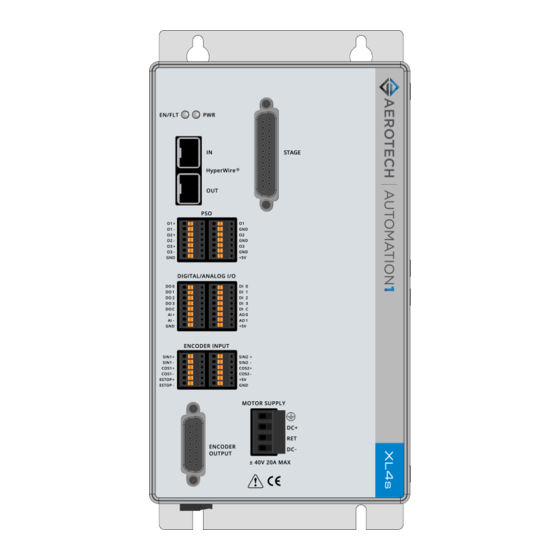
Page 1: Automation1 Xl4S High-Performance Voice-Coil Drive
Automation1 XL4s High-Performance Voice-Coil Drive HARDWARE MANUAL Revision 2.02... - Page 2 Global Technical Support Portal for information and support about your Aerotech, Inc. products. The website supplies software, product manuals, Help files, training schedules, and PC-to-PC remote technical support. If necessary, you can complete Product Return (RMA) forms and get information about repairs and spare or replacement parts.
-
Page 3: Table Of Contents
XL4s Hardware Manual Table of Contents Table of Contents Automation1 XL4s High-Performance Voice-Coil Drive Table of Contents List of Figures List of Tables EU Declaration of Conformity Agency Approvals Safety Procedures and Warnings Handling and Storage Installation Overview Chapter 1: XL4s Overview 1.1. -
Page 4: List Of Figures
List of Figures XL4s Hardware Manual List of Figures Figure 1-1: XL4s High Performance Linear Amplifier Figure 1-2: Functional Diagram Figure 1-3: Dimensions Figure 2-1: Control Supply Connections Figure 2-2: Motor Supply Connections Figure 2-3: Third-Party Power Supply Connection Figure 2-4:... -
Page 5: List Of Tables
XL4s Hardware Manual List of Tables List of Tables Table 1-1: Feature Summary Table 1-2: Electrical Specifications Table 1-3: Mounting Specifications Table 1-4: Environmental Specifications Table 1-5: Drive and Software Compatibility Table 2-1: Control Supply Connector Wiring Specifications Table 2-2: Mating Connector Part Numbers for the Control Supply Connector... - Page 6 List of Tables XL4s Hardware Manual This page intentionally left blank. www.aerotech.com...
-
Page 7: Eu Declaration Of Conformity
XL4s Hardware Manual EU Declaration of Conformity EU Declaration of Conformity Manufacturer Aerotech, Inc. Address 101 Zeta Drive Pittsburgh, PA 15238-2811 Product XL4s Model/Types This is to certify that the aforementioned product is in accordance with the applicable requirements of the following directive(s):... -
Page 8: Agency Approvals
U8 068995 0031 Rev. 00 Standards: CAN/CSA-C22.2 No. 61010-1:2012 , EN 61010-1:2010, UL 61010-1:2012 Visit https://www.tuev-sued.de/product-testing/certificates to view Aerotech's TÜV SÜD certificates. Type the certificate number listed above in the search bar or type "Aerotech" for a list of all Aerotech certificates. www.aerotech.com... -
Page 9: Safety Procedures And Warnings
To find the newest information about this product, refer to www.aerotech.com. If you do not understand the information in this manual, contact Aerotech Global Technical Support. IMPORTANT: This product has been designed for light industrial manufacturing or laboratory environments. - Page 10 Safety Procedures and Warnings XL4s Hardware Manual DANGER: To decrease the risk of electrical shock, injury, death, and damage to the equipment, obey the precautions that follow. 1. Before you do maintenance to the equipment, disconnect the electrical power. 2. Restrict access to the drive when it is connected to a power source.
-
Page 11: Handling And Storage
XL4s Hardware Manual Handling and Storage Handling and Storage Unpacking the Chassis IMPORTANT: All electronic equipment and instrumentation is wrapped in antistatic material and packaged with desiccant. Ensure that the antistatic material is not damaged during unpacking. Inspect the shipping container for any evidence of shipping damage. If any damage exists, notify the shipping carrier immediately. -
Page 12: Installation Overview
Installation Overview Installation Overview This image shows the order in which to make connections and settings that are typical to the XL4s. If a custom interconnect drawing was supplied with your system, that drawing is on your Storage Device and shows as a line item on your Sales Order in the Integration section. -
Page 13: Chapter 1: Xl4S Overview
XL4s Hardware Manual Chapter 1: XL4s Overview Chapter 1: XL4s Overview The XL4s is a high-performance linear amplifier designed to eliminate the non-linearities common with PWM amplifiers. The drive provides deterministic behavior, auto-identification, and easy software setup. Figure 1-1: XL4s High Performance Linear Amplifier Table 1-1: Feature Summary... -
Page 14: Figure 1-2: Functional Diagram
Chapter 1: XL4s Overview XL4s Hardware Manual The block diagram that follows shows a summary of the connector signals. Figure 1-2: Functional Diagram www.aerotech.com... -
Page 15: Electrical Specifications
XL4s Hardware Manual 1.1. Electrical Specifications 1.1. Electrical Specifications Table 1-2: Electrical Specifications Description XL4s Input Voltage ±40 VDC (max) Motor Supply Input Current 10 A (continuous) Input Voltage 85-240 VAC Input Frequency 50-60 Hz Control Supply Inrush Current 16 A Input Current 0.35 A (max) -
Page 16: Mechanical Specifications
1.2. Mechanical Specifications XL4s Hardware Manual 1.2. Mechanical Specifications 1.2.1. Mounting and Cooling Install the drive in an IP54 compliant enclosure to comply with safety standards. Make sure that there is sufficient clearance surrounding the drive for free airflow and for the cables and connections. -
Page 17: Dimensions
XL4s Hardware Manual 1.2.2. Dimensions 1.2.2. Dimensions Figure 1-3: Dimensions www.aerotech.com... -
Page 18: Environmental Specifications
1.3. Environmental Specifications XL4s Hardware Manual 1.3. Environmental Specifications The environmental specifications are listed below. Table 1-4: Environmental Specifications Operating: 0° to 40°C (32° to 104° F) Ambient Temperature Storage: -30° to 85°C (-22° to 185° F) The maximum relative humidity is 80% for temperatures that are Humidity less than 31°C and decreases linearly to 50% relative humidity at... -
Page 19: Chapter 2: Installation And Configuration
The Control Supply contains an internal filter. It is not necessary to use an external filter for CE compliance. IMPORTANT: Refer to local electrical safety requirements to correctly size external system wires. DANGER: Before you operate the XL4s, install a ground connection for your safety and to prevent damage to the equipment. Figure 2-1: Control Supply Connections... -
Page 20: Motor Supply Connector
Motor Supply and a power supply connected to the Control Supply. Motor power is applied to the XL4s at the four terminals of the Motor Supply connector. The DC+ input and the DC- input are connected to fuses inside the drive. Refer to... -
Page 21: External Power Supply Options
The output of each power supply must be specified to be used in positive or negative polarity. The XL4s controller can source 10 A peak current to each motor. This current must be supplied by the external power supply. A switching power supply must be rated for the peak current requirement of the system because the switching power supply might shut down if it is overloaded. -
Page 22: Minimizing Noise For Emc/Ce Compliance
Control and Motor Power Wiring using a TM3 Transformer 2.1.4. Minimizing Noise for EMC/CE Compliance IMPORTANT: The XL4s is a component designed to be integrated with other electronics. EMC testing must be conducted on the final product configuration. To reduce electrical noise, observe the following motor feedback and input power wiring techniques. -
Page 23: Hyperwire Interface
XL4s Hardware Manual 2.2. HyperWire Interface 2.2. HyperWire Interface The HyperWire bus is the high-speed communications connection from the controller. It operates at 2 gigabits per second. The controller sends all command and configuration information through the HyperWire bus. HyperWire cables can be safely connected to or disconnected from a HyperWire port while the PC and/or drive is powered on. -
Page 24: Position Synchronized Output Connector
When the PSO generates pulses, minimum latency occurs between the trigger condition and the output. Aerotech recommends that you use an RS-422 line receiver or an opto-isolator if your system: Uses cables with long lengths in work areas where a lot of electrical noise occurs. -
Page 25: Encoder Output Connector
XL4s Hardware Manual 2.4. Encoder Output Connector 2.4. Encoder Output Connector The Encoder Output interface echos the encoder signals out of the axis. Table 2-11: Encoder Output Connector Pinout Description In/Out/Bi Connector SIN- Output Reserved COS- Output Reserved Reserved Reserved PSO External Sync... -
Page 26: Figure 2-6: Pso External Sync Input Schematic
2.4. Encoder Output Connector XL4s Hardware Manual You can use the external PSO synchronization functions [A3200: PSOOUTPUT PULSE EXTSYNC command] to synchronize waveform generation with an external synchronization signal. When you activate this feature, the PSO Waveform module will not generate the configured waveform when an output event is received until the rising edge of the synchronization signal occurs. -
Page 27: Stage Motor And Feedback Connector
XL4s Hardware Manual 2.5. Stage Motor and Feedback Connector 2.5. Stage Motor and Feedback Connector You can only use the XL4s to control a DC Brush motor. Table 2-14: Stage Motor and Feedback Connector Pinout Description In/Out/Bi Pin Location Sine + Input Cosine + ... -
Page 28: Analog Encoder Inputs
2.5.1. Analog Encoder Inputs XL4s Hardware Manual 2.5.1. Analog Encoder Inputs The XL4s has one analog encoder input channel. The XL4s uses this input channel for position feedback. Use Encoder Tuning [A3200: Feedback Tuning] to adjust the value of the gain, offset, and phase balance controller parameters to get the best performance. -
Page 29: Digital And Analog I/O Connectors
XL4s Hardware Manual 2.6. Digital and Analog I/O Connectors 2.6. Digital and Analog I/O Connectors This connector has four digital, optically-isolated outputs, four digital, optically-isolated inputs, one differential analog input, and two analog outputs. Table 2-17: Digital and Analog I/O Connector A Pinout... -
Page 30: Digital Outputs
2.6.1. Digital Outputs XL4s Hardware Manual 2.6.1. Digital Outputs Optically-isolated solid-state relays drive the digital outputs. You can connect the digital outputs in current sourcing or current sinking mode but you must connect all four outputs in the same configuration. Refer to... -
Page 31: Figure 2-7: Digital Outputs Connected In Current Sourcing Mode
XL4s Hardware Manual 2.6.1. Digital Outputs Figure 2-7: Digital Outputs Connected in Current Sourcing Mode Figure 2-8: Digital Outputs Connected in Current Sinking Mode www.aerotech.com... -
Page 32: Digital Inputs
2.6.2. Digital Inputs XL4s Hardware Manual 2.6.2. Digital Inputs You can connect the digital inputs to current sourcing or current sinking devices but you must connect all four inputs in the same configuration. Refer to Figure 2-9 Figure 2-10. The digital inputs are not designed for high-voltage isolation applications. -
Page 33: Analog Outputs
XL4s Hardware Manual 2.6.3. Analog Outputs 2.6.3. Analog Outputs The analog outputs can be set from within a program or they can be configured to echo the state of select servo loop nodes. The analog outputs are set to zero when you power on the system or reset the drive. -
Page 34: Analog Inputs (Differential)
2.6.4. Analog Inputs (Differential) XL4s Hardware Manual 2.6.4. Analog Inputs (Differential) To interface to a single-ended, non-differential voltage source, connect the signal common of the source to the negative input and connect the analog source signal to the positive input. A floating signal source must be referenced to the analog common. -
Page 35: Encoder Input Connectors
XL4s Hardware Manual 2.7. Encoder Input Connectors 2.7. Encoder Input Connectors The drive has one auxiliary encoder input channel. The encoder interface accepts an RS-422 differential line driver. You cannot use the auxiliary encoder input channels to close the position loop. -
Page 36: Figure 2-13: Encoder Input Connector Encoder Connections
2.7. Encoder Input Connectors XL4s Hardware Manual Figure 2-13: Encoder Input Connector Encoder Connections www.aerotech.com... -
Page 37: Emergency Stop Sense Input
XL4s Hardware Manual 2.7.1. Emergency Stop Sense Input 2.7.1. Emergency Stop Sense Input WARNING: It is your responsibility to assemble the external safety circuits of your system to minimize the risk to the operator. IMPORTANT: The ESTOP sense input is not a safety-rated system. -
Page 38: Laser Output Polarity Switch
2.8. Laser Output Polarity Switch XL4s Hardware Manual 2.8. Laser Output Polarity Switch The Laser Output Polarity switches are reserved for future use. Figure 2-15: Laser Output Polarity Switch Location www.aerotech.com... -
Page 39: Sync Port
XL4s Hardware Manual 2.9. Sync Port 2.9. Sync Port The Sync port is a bi-directional high speed proprietary interface that lets you transmit encoder signals between drives. This is typically used for multi-axis PSO applications where one or two drives send their encoder signals to a main drive that has the PSO logic and PSO output signal. - Page 40 2.10. PC Configuration and Operation Information XL4s Hardware Manual This page intentionally left blank. www.aerotech.com...
-
Page 41: Chapter 3: Maintenance
Chapter 3: Maintenance IMPORTANT: For your own safety and for the safety of the equipment: Do not remove the cover of the XL4s. Do not attempt to access the internal components. A fuse that needs to be replaced indicates that there is a more serious problem with the system or setup. -
Page 42: Preventative Maintenance
DANGER: Before you clean the XL4s, disconnect the electrical power from the drive. Use a clean, dry, soft cloth to clean the XL4s. If necessary, use a cloth that is moist with water or isopropyl alcohol. If you use a moist cloth, make sure that moisture does not go into the drive. Also make sure that it does not go onto the outer connectors and components. -
Page 43: Board Assembly
XL4s Hardware Manual 3.2. Board Assembly 3.2. Board Assembly Figure 3-1 highlights the important components located on the control board. DANGER: Before you open the XL4s chassis, you must disconnect the Mains power connection. Figure 3-1: Control Board Assembly Table 3-4:... -
Page 44: Figure 3-2: Power Board Assembly
3.2. Board Assembly XL4s Hardware Manual DANGER: Before you open the XL4s chassis, you must disconnect the Mains power connection. Figure 3-2: Power Board Assembly Table 3-5: Power Board Fuse Specifications Aerotech Third Party P/N Fuse Description Size Motor Bus Supply 10 A S.B. -
Page 45: Appendix A: Warranty And Field Service
All Other Repairs - After Aerotech's evaluation, the buyer shall be notified of the repair cost. At such time the buyer must issue a valid purchase order to cover the cost of the repair and freight, or authorize the product(s) to be shipped back as is, at the buyer's expense. - Page 46 Aerotech's approval. On-site Warranty Repair If an Aerotech product cannot be made functional by telephone assistance or by sending and having the customer install replacement parts, and cannot be returned to the Aerotech service center for...
-
Page 47: Appendix B: Revision History
XL4s Hardware Manual Appendix B: Revision History Appendix B: Revision History Revision Description 2.02 General Update The following sections have been updated: 2.01 EU Declaration of Conformity Agency Approvals 2.00 General Update 1.04 Updated Section 1.2. 1.03 Updated Table 1-1 1.02... - Page 48 Appendix B: Revision History XL4s Hardware Manual This page intentionally left blank. www.aerotech.com...
-
Page 49: Index
XL4s Hardware Manual Index Index Control Supply Connections Control Supply Connector Mating Connector Part Numbers Wiring Specifications 2011/65/EU cooling vents, inspecting 2014/35/EU Customer order number Agency Approvals Declaration of Conformity Altitude Digital / Analog I/O Connectors Ambient Temperature Analog Inputs (Differential) - Page 50 Index XL4s Hardware Manual Encoder Input Connector Specifications HyperWire Encoder Output Connector Cable Part Numbers Encoder Output Connector Mating Card Part Number Connector Part Numbers Encoder Output Connector Pinout Encoder Outputs Schematic Input Power Connections Environmental Specifications inspecting cooling vents...
- Page 51 XL4s Hardware Manual Index Output Voltage Specifications Overview Analog Encoder Input Analog Input (Digital / Analog I/O B Connector) Analog Output (Digital and Analog I/O Connector) Control Board Fuses packing list Control Supply Connector Wiring PC Configuration and Operation Information...
- Page 52 Index XL4s Hardware Manual This page intentionally left blank. www.aerotech.com...
Need help?
Do you have a question about the XL4s and is the answer not in the manual?
Questions and answers