Subscribe to Our Youtube Channel
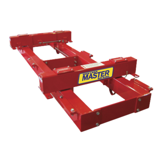
Summary of Contents for Rice Lake Master 221DB
- Page 1 Master 221DB ™ Belt Scale Weigh Frame Installation Manual January 4, 2022 PN 169659 Rev C...
- Page 2 All information contained within this publication is, to the best of our knowledge, complete and accurate at the time of publication. Rice Lake Weighing Systems reserves the right to make changes to the technology, features, specifications and design of the equipment without notice.
-
Page 3: Table Of Contents
Overload Bolts..................11 Technical training seminars are available through Rice Lake Weighing Systems. - Page 4 221DB Belt Scale Rice Lake continually offers web-based video training on a growing selection of product-related topics at no cost. Visit www.ricelake.com/webinars www.RiceLake.com Visit our website...
-
Page 5: Introduction
Not every application is suited for a belt scale; this has to be analyzed by a Rice Lake Weighing Systems application specialist. To achieve the optimum result, the Master™ belt scale series has been developed for a number of applications and for every type of conveyor. -
Page 6: Safety
Do not operate or work on this equipment unless this manual has been read and all instructions are understood. Failure to follow the instructions or heed the warnings could result in injury or death. Contact any Rice Lake Weighing Systems dealer for replacement manuals. -
Page 7: Installation
Proper covers may be required to prevent air flow from interfering with the belt scale. Side guards and belt skirting should not be in contact with the weighing area of the belt scale. © Rice Lake Weighing Systems ● All Rights Reserved... -
Page 8: Mechanical Installation
221DB Belt Scale Mechanical Installation The mechanical installation of a belt scale consists of mounting the weigh frame, the speed pickup and the junction box. Belt removed for illustration purposes only. Note 1. Determine the location for the weighing idler. This location should be at least five idlers after the load point of the conveyor and at least five idlers before the head pulley. - Page 9 Ensure they do not interfere with lever arm. Clamps 1.5 in (40 mm) Figure 2-5. Use Clamps to Position Weldment 10. After weldment is in place and secured, re-install lever arms. Figure 2-6. Re-install Lever Arms © Rice Lake Weighing Systems ● All Rights Reserved...
- Page 10 221DB Belt Scale 11. Repeat installation on opposite side of conveyor. Make sure assemblies are aligned with each other. 12. Mount idler station to lever arms. Figure 2-7. Mount Idler 13. Run strings on the conveyor (three before the scale and three past the scale) and shim the idlers to the same plane. Figure 2-8.
-
Page 11: Electrical Installation
Commissioning should be performed by service engineers who are trained and experienced with the subject. 2.3.1 Mechanical Adjustments Mechanical adjustments must be made to ensure the scale is free of any tension. If necessary, the load cell can be adjusted. © Rice Lake Weighing Systems ● All Rights Reserved... -
Page 12: Maintenance
221DB Belt Scale Maintenance Regular maintenance is essential to prevent errors or unnecessary down time. The supplier does not accept any responsibility for the consequences of not performing the maintenance recommended in this section. Maintenance It is important to guarantee the safety of personnel during maintenance work and to assure no accidents will happen. -
Page 13: List Of Parameters For Belt Scale
Idler spacing in (mm) Belt angle of incline ° Belt speed ft/s (m/s) Speed pickup Pulses per revolution Non-driven drum in (mm) Total belt length ft (m) © Rice Lake Weighing Systems ● All Rights Reserved... - Page 14 221DB Belt Scale This page is left intentionally blank. www.RiceLake.com Visit our website...
-
Page 15: Appendix
4. Tighten the jam nuts on the overload stop. 5. Remove the tension on the shipping stop to allow full travel of the lever arm. 6. Repeat on the opposite side. © Rice Lake Weighing Systems ● All Rights Reserved... - Page 16 221DB Belt Scale www.RiceLake.com Visit our website...
- Page 18 Specifications subject to change without notice. Rice Lake Weighing Systems is an ISO 9001 registered company. 230 W. Coleman St. • Rice Lake, WI 54868 • USA U.S. 800-472-6703 • Canada/Mexico 800-321-6703 • International 715-234-9171 • Europe +31 (0)26 472 1319...


Need help?
Do you have a question about the Master 221DB and is the answer not in the manual?
Questions and answers