Table of Contents

Advertisement

Operator & Safety
Keep this manual with machine at all times.
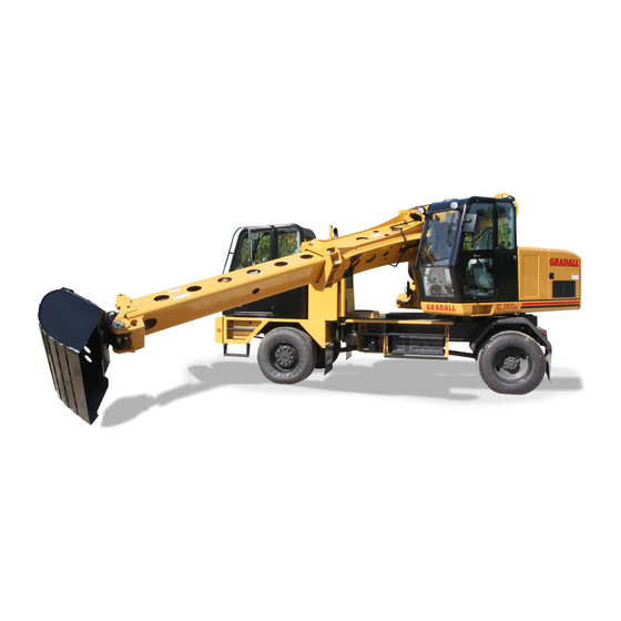
XL3100V - XL4100V - XL5100V
(Railgear) S/N 4140R00100 & After
(Railgear) S/N 4130R00100 & After
This manual, and all manuals for the Gradall Hydraulic
Excavator product line, can be viewed or downloaded, free-of-charge, at
XL4130V
(4x2) S/N 3120000375 & After
(4x4) S/N 3140000378 & After
(6x4) S/N 4140000100 & After
(6x6) S/N 4160000088 & After
(6x4) S/N 5140000100 & After
(6x6) S/N 5160000100 & After
80884013
Revised
December 7th, 2018
www.mygradall.com
https://tractormanualz.com/
Manual

Advertisement

Table of Contents
loading
Need help?

Need help?

Do you have a question about the XL3100V and is the answer not in the manual?

Questions and answers

Summary of Contents for Gradall XL3100V

  • Page 1 (6x6) S/N 4160000088 & After (6x4) S/N 5140000100 & After (6x6) S/N 5160000100 & After 80884013 Revised December 7th, 2018 This manual, and all manuals for the Gradall Hydraulic Excavator product line, can be viewed or downloaded, free-of-charge, at www.mygradall.com https://tractormanualz.com/...
  • Page 2 IMPORTANT! - If printed, or downloaded in electronic format, this is an uncontrolled copy of the manual. The current version can be viewed/downloaded at www.mygradall.com Gradall is a registered trademark for hydraulic excavators, industrial maintenance machines, attachments and other components manufactured and marketed by Gradall Industries, Inc.
  • Page 3 Revision Log Revision Log REVISION LOG February 12th, 2016 - A - Original Issue of Manual April 14th, 2016 - B - Added battery shutdown warning January 6th, 2017 - C - Added description to chassis lube points in Section 5. Revised Upper Cab Heater Spec.
  • Page 4: Read This First

    Due to continuous product improvements, Gradall Industries, Inc. reserves the right to make specification changes without prior notification. Contact Gradall Industries, Inc.
  • Page 5: Other Publications Available

    Inc. or the local authorized Gradall representative for information regarding safety- related bulletins which may have been issued for this product. Gradall Industries, Inc. sends safety related bulletins to the owner of record of this machine. Contact Gradall Industries, Inc. to ensure that the current owner records are updated and accurate.
  • Page 6 Read This First NOTES: https://tractormanualz.com/ 80884013...
  • Page 7: Table Of Contents

    Table of Contents Table of Contents TABLE OF CONTENTS Revision Log Read This First Operator Qualifications................b Modifications ..................... b Other Publications Available ..............c Table of Contents Section 1 - General Safety Practices Hazard Classification System............1-1 Safety Alert System and Safety Signal Words......1-1 General Precautions ..............1-1 Operation Safety ................1-2 Electrical Hazards...............1-2...
  • Page 8 Table of Contents Turn Signal/High Beam/Hazards Lever........2-28 Upperstructure Cab Components ..........2-30 Upperstructure Cab Controls & Indicators ........2-32 Electronic Monitoring Unit ............2-32 Right Hand Arm Pod ..............2-34 Left Hand Arm Pod..............2-36 Joystick Control Pattern Selection ........... 2-38 Joystick Controls ..............
  • Page 9 500 Hour Maintenance Schedule ..........5-7 Semi-Annual (750 Hour Maximum) Maintenance Schedule..5-8 Annual (1500 Hour Maximum) Maintenance Schedule ....5-9 Undercarriage Lubrication Schedules .........5-10 Monthly (125 Hour Maximum) Lubrication Schedule - XL3100V..5-10 Monthly (125 Hour Maximum) Lubrication Schedule - XL4100V & XL5100V ............5-12 Semi-Annual (750 Hour Maximum) Lubrication Schedule - XL3100V ...............5-14...
  • Page 10 Table of Contents Semi-Annual (750 Hour Maximum) Lubrication Schedule - XL4100V & XL5100V............ 5-16 Upperstructure Lubrication Schedules........5-18 Daily or Shift (10 Hour Maximum) Lubrication Schedule ..5-18 Annual (1500 Hour Maximum) Lubrication Schedule....5-19 Operator Maintenance Instructions..........5-20 10 Hours................... 5-20 50 Hours...................
  • Page 11: Section 1 - General Safety Practices

    Section 1 - General Safety Practices SECTION 1 - GENERAL SAFETY PRACTICES HAZARD CLASSIFICATION SYSTEM Safety Alert System and Safety Signal Words DANGER OW0010 DANGER indicates an imminently hazardous situation which, if not avoided, will result in death or serious injury. WARNING OW0021 WARNING indicates a potentially hazardous situation which, if not avoided, could...
  • Page 12: Operation Safety

    Section 1 - General Safety Practices OPERATION SAFETY Electrical Hazards 10 FT (3 M) OAC0330 • This machine is not insulated and does not provide protection from contact or being near electrical current. • NEVER operate the excavator in an area where overhead power lines, overhead or underground cables, or other power sources may exist without ensuring the appropriate power or utility company de-energizes the lines.
  • Page 13: Swing Hazards

    Section 1 - General Safety Practices Swing Hazards OAC0340 • Keep others away from machine while in operation. Ensure others are clear of the swing radius prior to swinging upperstructure. • Never carry a water can, equipment, or other worker’s tools or personal items on the machine.
  • Page 14 Section 1 - General Safety Practices OAC1240 • The circle of safety is a circle around the excavator with the boom at full extension. • Establish and inform others of the circle of safety. Keep others from entering into the circle of safety. https://tractormanualz.com/ 80884013...
  • Page 15: Slip And Fall Hazard

    Section 1 - General Safety Practices Slip and Fall Hazard OAC0350 • Always maintain 3-point contact using proper hand holds and steps provided when mounting or dismounting. Never grab control levers or steering wheel when mounting or dismounting machine. • Repair or replace damaged steps and grab handles. •...
  • Page 16: Crush Hazards

    Section 1 - General Safety Practices Crush Hazards OAC1250 • Do not lean on boom or reach into boom holes, bucket linkage or boom rollers until the attachment or boom is resting on the ground and the engine is stopped. •...
  • Page 17 Section 1 - General Safety Practices OAC1020 • Never permit anyone under boom, attachment or load. Rest boom or attachment on ground and stop engine before permitting anyone to work beneath boom or behind cradle. https://tractormanualz.com/ 80884013...
  • Page 18: Travel Hazards - Remote And Driving

    Section 1 - General Safety Practices Travel Hazards - Remote and Driving OAC0710 • Look out for and avoid other personnel, machinery and vehicles in the area. Use a spotter if you do not have a clear view. • Before moving be sure of a clear path for undercarriage, boom and counterweight and sound horn.
  • Page 46: Section 2 - Pre-Operation And Controls

    Section 2 - Pre-Operation and Controls UNDERCARRIAGE CAB CONTROLS & INDICATORS Dash Panel RPM/X1000 p si 10 0 INTERAXLE FUEL 0 0 0 0 0 0 DIFFERENTIAL 1000 WATER HOURS 1/10 °F FRONT AXLE DRIVE BATTERY AXLE DIFFERENTIAL O IL P.S.I WIPER WASHER...
  • Page 62 The control pattern selection switch allows the operator to select from three joystick control patterns; GRADALL, SAE and JOHN DEERE. The pattern must be selected with the ignition key in the “OFF” position. If a new pattern is selected while the engine is running, it will not change until the engine is turned off then restarted.
  • Page 73 Section 3 - Operation CHECKS BEFORE UNDERCARRIAGE OPERATION This section outlines the checks to be performed at the beginning of each work shift or at each change of operator. Refer to page 3-34 for procedure to check brakes after remote control operation and digging. Repair any deficiencies before driving or operating the equipment.
  • Page 78 Section 3 - Operation Parking Brake OAC0550 • Two parking brake controls are provided; one on undercarriage dashboard (1) and another on left hand pod panel in the upperstructure (2). The switch in the upperstructure cab is inoperative when in travel mode. Undercarriage park brake must remain applied when in remote mode.
  • Page 79 Section 3 - Operation NOTES: 80884013...
  • Page 80 Section 3 - Operation TRAVEL MODE POWER TRAIN Shifting Gears The transmission is automatically shifted with 6 forward speeds plus reverse. Ranges are selected by pressing and releasing the button for the desired range on the Transmission Shift Selector. For example, press and release the “N” button to select Neutral, the “D”...
  • Page 82 Section 3 - Operation Differential Lock Normally, differential lock will engage and disengage immediately in response to lock/unlock toggle; however, differential “wind-up”, or misalignment can delay engagement/disengagement. In this event, reversing direction of travel and/or operation of steering while traveling may relieve differential “wind-up”. Indicator light shows actual state of lock engagement/disengagement.
  • Page 83 Section 3 - Operation 3. Front Axle Drive Switch (if equipped): To Engage: • Stop machine. • Move toggle lever on dash to the “I” position. Notice!: Engaging front axle drive while undercarriage is moving will damage transfer case. Stop undercarriage before engaging front axle drive. To Disengage: •...
  • Page 86 Section 3 - Operation CHECKS BEFORE REMOTE CONTROL OPERATION This section outlines the checks to be performed at the beginning of each work shift or at each change of operator. Repair any deficiencies before driving or operating the equipment. During warm-up period, check the following: •...
  • Page 88 Section 3 - Operation Digging Brake When in remote mode, the digging brakes are automatically applied upon releasing the travel pedal. • When activated, the digging brake is applied to all wheels to hold the undercarriage stationary while the excavator is digging. •...
  • Page 89 Section 3 - Operation REMOTE MODE POWER TRAIN Driving Undercarriage from Upperstructure Cab Remote travel is possible at all times except when indicated by an audible alarm and the travel lockout symbol being illuminated on the monitor. When this condition exists, the directional travel pedal must be slowly and carefully activated in both directions until the light and alarm turn off.
  • Page 99 Section 3 - Operation General There is a lift capacity difference between the excavator’s best and worst lift positions. Just because it can lift a load from one point does not mean it can safely deliver the load to any other point. Prior to lifting and placing a load, map out the lift, swing, and lower path to ensure that capacity, both hydraulic and stability tipping limits, are not exceeded.
  • Page 101: 3.13 Lift Capacity

    Section 3 - Operation 3.13 LIFT CAPACITY LOAD RADIUS 10’ (3.0m) 15’ (4.6m) 20’ (6.1m) 25’ (7.6m) LOAD POINT HEIGHT MAXIMUM OVER OVER OVER OVER OVER OVER OVER OVER OVER OVER RADIUS SIDE SIDE SIDE SIDE SIDE 5715 5715 27’ 4” 5070 5070 20’...
  • Page 102 -557lbs. (253kg) Note: Bucket adjustment values are 87% of the actual bucket weights. Any weight adjustment for Gradall buckets not shown can be calculated by multiplying actual bucket weight by .87. • The load point is located on the bucket pivot point, including load listed for maximum radius.
  • Page 103: 3.14 Remote Mode Engine Shutdown

    Section 3 - Operation 3.14 REMOTE MODE ENGINE SHUTDOWN To shutdown the excavator, park in a safe location on flat level ground and away from other equipment and/or traffic lanes. From Upperstructure Cab: 1. Stop machine by removing pressure from foot pedals. 2.
  • Page 104: 3.15 Return To Travel Mode

    Section 3 - Operation 3.15 RETURN TO TRAVEL MODE Preparing Upperstructure for Undercarriage Operation 1. Check operation of brakes after remote operation and digging. 2. Position unit on level surface, apply digging brake and stop engine. Check the following for damage; brake actuator chambers and rods, brake actuator brackets, and slack adjusters.
  • Page 105: Boom Stow Procedure

    Section 3 - Operation Boom Stow Procedure 1. With teleboom extended, stow boom in boom rest. 2. Retract telescope boom until the boom position decal is visible in the bottom smaller hole in the main boom, as illustrated: OAC2690 Securing Unit for Driving Drive to and from job site only under the following conditions: OAC0640 •...
  • Page 106: 3.16 Parking The Excavator

    Section 3 - Operation 3.16 PARKING THE EXCAVATOR Precaution If the machine is in remote and must be shut down for an extended period of time, return the machine to conventional undercarriage operation. Avoid parking on roads or highways. If it cannot be avoided, or in case of emergency, display warning flags, flares or flashing lights.
  • Page 107: 3.17 Preservation & Storage

    Section 3 - Operation 3.17 PRESERVATION & STORAGE • Park the machine following the procedure on page 3-36. • If it is impractical to activate functions regularly, and if freezing temperatures are expected, remove batteries and store in a warm location. •...
  • Page 108 Section 3 - Operation This Page Intentionally Left Blank https://tractormanualz.com/ 3-38 80884013...
  • Page 109: Section 4 - Attachments

    • An overextended or overloaded excavator can tip over with little or no warning and cause death or serious injury to the operator and/or those working nearby. • Gradall cannot assure the ability of a non-approved attachment to perform its intended function safely.
  • Page 110: Excavating Buckets

    Section 4 - Attachments Excavating Buckets Size Cu. Yd. 24" (610mm) 30" (762mm) 36" (914mm) 42" (1.07m) 48" (1.22m) OAC0590 Installation Procedure • Refer to "Adapter Attachment Installation" beginning on page 4-4. Ditching Buckets Size Cu. Yd. 30" (.80m) 60" (1.52m) 66"...
  • Page 111: Trenching Buckets

    Section 4 - Attachments Trenching Buckets Size Cu. Yd. 15" (381mm) 21" (533mm) OAC0720 Installation Procedure • Refer to "Adapter Attachment Installation" beginning on page 4-4. Pavement Removal Bucket Size Cu. Yd. 18" (.50m) 24" (.60m) OAC0730 28" (.70m) 40" (1.02m) Installation Procedure •...
  • Page 112: Dredging Bucket

    Section 4 - Attachments Dredging Bucket Size Cu. Yd. 72" (1.83m) 1-1/8 OAC0740 Installation Procedure • Refer to "Adapter Attachment Installation" beginning on page 4-4. Grading Blade Size Cu. Yd. 8’ (2.4m) OAC0750 Installation Procedure • Refer to "Adapter Attachment Installation" beginning on page 4-4. https://tractormanualz.com/ 80884013...
  • Page 113: Adapter Attachment Installation

    Section 4 - Attachments ADAPTER ATTACHMENT INSTALLATION OAC0760 1. Wedge Bolts 2. Bucket Adapter 3. Bucket Bars Installation Procedure: 1. Be sure wedge bolts (1) are secured in storage position (toward rear) and position bucket adapter (2) above bucket bar (3) as shown. OAC0770 2.
  • Page 114 Section 4 - Attachments 3. Move adapter toward "bucket close" position until outer end of adapter contacts bucket. Ensure proper alignment and continue to close until adapter contacts stops (1). OAC0790 4. Only use the nuts to move wedge bolts forward to position wedge between adapter and bucket bar.
  • Page 115: Section 5 - Lubrication & Maintenance

    Always check hourmeter and date at beginning of shift to be certain services are performed at proper intervals. Perform service at whichever interval comes first. Note: Failure To Use Gradall Hydraulic Filter Elements Could Void Warranty. FALL HAZARD. Use extreme caution when checking WARNING items beyond your normal reach.
  • Page 116: General Maintenance Instructions

    • Apply a light coating of engine oil to all linkage pivot points. • Drain engine and gear cases after operating when oil is hot. • Check all lubricant and coolant levels when cool. MACHINE DAMAGE. Contact Gradall before welding WARNING on machine. Welding could damage wires, electronic processors, hoses, and tubes.
  • Page 117: Service & Maintenance Schedules

    Section 5 - Lubrication & Maintenance SERVICE & MAINTENANCE SCHEDULES Daily or Shift (10 Hour Maximum) Maintenance Schedule * Drain air tanks daily. To prevent possible damage to emission controls components, wait a minimum of 10 minutes after shutting off engine before draining air tanks.
  • Page 118: Weekly (50 Hour Maximum) Maintenance Schedule

    Section 5 - Lubrication & Maintenance Weekly (50 Hour Maximum) Maintenance Schedule EVERY Check Tilt Check Tilt Check Swing Follow Lubrication Transmission Level Transmission Level Transmission Schedule Oil Level EVERY Check Power Inspect Air Filter Check Brake Check Tire Drain Fuel/ Steering Fluid Vacuator System Air...
  • Page 119: Monthly (125 Hour Maximum) Maintenance Schedule

    Section 5 - Lubrication & Maintenance Monthly (125 Hour Maximum) Maintenance Schedule EVERY Check Boom Roller Alignment EVERY Check Clean Hydraulic Check Axle Check Battery Oil Level Fan Belt Reservoir Breather Follow Lubrication Inspect Check Check Transfer Schedule and Clean Transmission Case Oil Level Cooler Cores...
  • Page 120: 1St 30 Days (250 Hrs Max) & 250 Hour Maintenance Schedule.5-6

    Section 5 - Lubrication & Maintenance 1st 30 Days (250 hrs Max) & 250 Hour Maintenance Schedule 1st 30 DAYS Drain and Refill Drain and Refill Apply Open Follow Lubrication Torque all Items Swing Transmission Tilt Transmission Gear Lube to Schedule Listed in Tilt Gear Teeth...
  • Page 145: Section 6 - Emergency Procedures

    Section 6 - Emergency Procedures SECTION 6 - EMERGENCY PROCEDURES LOSS OF POWER The engine will de-rate if a problem develops. If this occurs, place the boom in the boom rest as soon as possible. Make all necessary repairs before continued operation.
  • Page 147: Section 7 - Specifications

    PRODUCT SPECIFICATIONS Lubrication & Fluid Capacities Note: Lubricants described in this table are used in standard machines when they are shipped from Gradall Industries, Inc. Engine Crankcase Oil Capacity with Filter Change (4-cylinder) ........17.2 quarts (16.3 liters) Capactiy with Filter Change (6-cylinder) ........28.0 quarts (26.5 liters) Type of Oil ..............
  • Page 148 Front Axle (XL3100V 4x4) Capacity..................27 pints (12,8 liters) Type of Fluid .................80w90 (8053-3027) Front Axle Wheel Ends (XL3100V 4x2; XL4100V 6x4 & XL5100V 6x4; XL4130V) Capacity..............4 ounces (0,1 liters) (per wheel) Type of Fluid .................80w90 (8053-3027) Front Axle (XL4100V 6x6 & XL5100V 6x6) Capacity..................
  • Page 149: Tires

    Section 7 - Specifications Swing Transmission Capacity ................... 4.75 quarts (4,5 liters) Type of Fluid .................80w90 (8053-3027) Swing Bull Gear Capacity ....................as required Type of Fluid ..............Extreme Pressure Lube #2 Tilt Transmission Capacity ................. 32-34 ounces (0,9-1,0 liters) Type of Fluid .................80w90 (8053-3040) Tilt Bull Gear Capacity ....................
  • Page 150: Weight

    Gross Vehicle Axle Weight Rating (6x4)........66,000 lb (29,937 kg) Gross Vehicle Axle Weight Rating (6x6)........69,000 lb (31,928 kg) Note: Refer to detailed specification sheet for additional machine weight information. Specification sheets can be viewed/downloaded at www.gradall.com Dimensions XL3100V Wheelbase.................... 13.4 ft (4,1 m) Ground Clearance ................10 in (254 mm)
  • Page 151 Transport Height (without bucket) (6x4) ..........11.2 ft (3,4 m) Transport Height (without bucket) (6x6) ..........11.5 ft (3,5 m) Transport Width ..................8.6 ft (2,6 m) Note: Refer to detailed specification sheet for additional machine dimension information. Specification sheets can be viewed/downloaded at www.gradall.com 80884013...
  • Page 152: Torque Chart

    Section 7 - Specifications TORQUE CHART To check Gradall torque values, set the torque wrench at 95% of the rated torque values and check fastener. If the torque wrench releases before the fastener moves, assume fastener torque is correct. When setting Gradall torque values, use the values given on the following chart.
  • Page 153: Undercarriage

    Section 7 - Specifications Tilt Transmission Quantity ..................31 pints (14,7 liters) Thread Size (grade) ..............80w90 (1440-3126) Torque (lubricated) ............200-215 lb-ft (272-292 Nm) Wheel Lug Nuts Quantity .........................ALL Thread Size (grade) ..................3/4-10 (8) Torque (lubricated) ............450-500 lb-ft (610-678 Nm) Front Axle U-Bolt Nuts Quantity .........................ALL Thread Size (grade) ..................
  • Page 156 Section 7 - Specifications This Page Intentionally Left Blank 7-10 80884013...
  • Page 157 https://tractormanualz.com/...
  • Page 158 https://tractormanualz.com/...
  • Page 159 https://tractormanualz.com/...
  • Page 160 https://tractormanualz.com/...
  • Page 161: Index

    Index Index Adapter Attachment Installation 4-5–4-6 Grading Blade ........4-4 Air Tanks ........5-25 Approved Attachments ..... 4-1 Hazards Lever.........2-28 Attachment Operation ...... 4-1 High Beam Lever ......2-28 Attachments ........4-1 Hydraulic Oil Level ......5-21 Axles..........7-2 Hydraulic Reservoir Breather..5-27 Hydraulic Return Filter Element ..5-23 Battery ........
  • Page 162 Index Operator Seat ......... 2-43 Trenching Buckets ......4-3 Turn Signal Lever......2-28 Park Brake Switch, Upperstructure 2-46 Parking Procedure......3-36 Undercarriage Cab......2-10 Pavement Removal Bucket ....4-3 Undercarriage Cab Controls & Indicators 2-22 Personal Protection Equipment ..1-13 Upperstructure Cab......2-30 Placing a Load........ 3-28 Upperstructure Cab Controls &...
  • Page 163 Hand Signals OY1090 OY1100 OY1110 EMERGENCY STOP - With both STOP - With either arm extended STOP ENGINE - Draw thumb or arms extended laterally, hands laterally, hand open downward, forefinger across throat. open downward, move arms back move arm back and forth. and forth.
  • Page 164 Gradall Industries, Inc. 406 Mill Ave SW New Philadelphia OH. 44663 Phone: (330) 339-2211 Customer Support Toll Free: (800) 445-4752 Fax: (330) 339-3579 www.gradall.com Gradall Europe Division of Tieluiska Harkkokatu 6 FI-05800 Hyvinkää, Finland Tel. +358 (0)20 759 0400 Fax. +358 (0)19 485 278 VAT:FI05973039 www.gradalleurope.com...

This manual is also suitable for:

Xl4100vXl5100vXl4130v

Table of Contents