Table of Contents
Advertisement
Quick Links
© Copyright 2001, 2002
EVERTZ MICROSYSTEMS LTD.
5288 John Lucas Drive, Burlington, Ontario, Canada, L7L 5Z9
Phone: 905-335-3700
Fax:
905-335-3573
Internet:
Sales:
Tech Support: service@evertz.com
Web Page:
Version 1.3 September 2002
The material contained in this manual consists of information that is the property of Evertz Microsystems and is
intended solely for the use of purchasers of the HD9155 Series HD Production Afterburner. Evertz Microsystems
expressly prohibits the use of this manual for any purpose other than the operation of the device.
All rights reserved. No part of this publication may be reproduced without the express written permission of
Evertz Microsystems Ltd. Copies of this guide can be ordered from your Evertz products dealer or from Evertz
Microsystems.
HD9155 and HD9155Q Series
High Definition
Production Afterburner
Instruction Manual
sales@evertz.com
http://www.evertz.com
Advertisement
Table of Contents

Subscribe to Our Youtube Channel
Related Manuals for evertz HD9155 Series


Summary of Contents for evertz HD9155 Series
- Page 1 Version 1.3 September 2002 The material contained in this manual consists of information that is the property of Evertz Microsystems and is intended solely for the use of purchasers of the HD9155 Series HD Production Afterburner. Evertz Microsystems expressly prohibits the use of this manual for any purpose other than the operation of the device.
- Page 3 WARNING Changes or Modifications not expressly approved by Evertz Microsystems Ltd. could void the user’s authority to operate the equipment. Use of unshielded plugs or cables may cause radiation interference.
- Page 5 Model HD9155 Production Afterburner Manual REVISION HISTORY REVISION DESCRIPTION DATE Original Version Oct 01 Added HD9155-AUD May 02 1.1.1 Updated Firmware upgrade instructions for AES and AUD versions Jun 02 Added HD9155Q and HD9155Q-AUD Jun 02 Updated Specifications Sep 02 Revision 1.3...
-
Page 7: Table Of Contents
Model HD9155 Production Afterburner Manual TABLE OF CONTENTS OVERVIEW............................1 1.1. HOW TO USE THIS MANUAL ....................2 INSTALLATION........................... 1 2.1. REAR PANEL OVERVIEW ......................1 2.1.1. Downconverter Video Connections (Models HD9155, HD9155-AES, HD9155-AUD) ..2 2.1.2. Downconverter Video Connections (Models HD9155Q, HD9155Q-AUD) ...... 2 2.1.3. - Page 8 Model HD9155 Production Afterburner Manual 4.1.3.4. Help Menu......................3 4.1.4. 9150 Configware™ Screens ................... 4 4.1.4.1. Inputs Screen ..................... 4 4.1.4.2. Outputs Screen ....................5 4.1.4.3. Windows Screen ....................6 4.1.4.4. Parameters Screen .................... 7 SYSTEM PARAMETERS ........................1 5.1. 9155 PARALLEL I/O PIN FUNCTIONS ..................2 TECHNICAL DESCRIPTION.......................
- Page 9 Model HD9155 Production Afterburner Manual 6.4.21. WIN OP1 STS (21) Output 1 - Parallel Connector Pin 9 status ........10 6.4.22. WIN OP2 STS (22) Output 2 - Parallel Connector Pin 5 status ........10 6.4.23. WIN SLTC (23) Smoothed LTC Stats ................11 6.4.24.
- Page 10 Model HD9155 Production Afterburner Manual This page left intentionally blank CONTENTS Revision 1.3...
- Page 11 Model HD9155 Production Afterburner Manual CHAPTER 1: OVERVIEW TABLE OF CONTENTS OVERVIEW............................1 1.1. HOW TO USE THIS MANUAL ....................2 OVERVIEW Revision 1.3...
- Page 12 Model HD9155 Production Afterburner Manual This page left intentionally blank OVERVIEW Revision 1.3...
-
Page 13: Overview
HDTV input video to SDI and analog standard definition video. When the input video is in the 1080p/24sF format the HD9155 Series Production Afterburners also create a 2:3 pulldown on the output video to create a 30 Fps output. -
Page 14: How To Use This Manual
Configware™, System Parameters, and Technical Description. The overview section contains a brief overview of the HD9155 series operation and features, a tutorial on 2:3 pulldown and a glossary to define concepts and terms used throughout the remainder of the manual. We highly recommend taking the time to become familiar with the terms and concepts described here before proceeding into the rest of the manual. - Page 15 Model HD9155 Production Afterburner Manual Chapter 4 gives detailed information on installing and connecting the 9150 Configware™ software. The Configware™ software allows you to customise the operation of the HD9155. Chapter 5 gives a discussion of how the default operation of the Production Afterburner can be changed using System Parameters.
- Page 16 Model HD9155 Production Afterburner Manual This page left intentionally blank Page 1-4 OVERVIEW Revision 1.3...
- Page 17 Model HD9155 Production Afterburner Manual CHAPTER 2: INSTALLATION TABLE OF CONTENTS INSTALLATION........................... 1 2.1. REAR PANEL OVERVIEW ......................1 2.1.1. Downconverter Video Connections (Models HD9155, HD9155-AES, HD9155-AUD) ..2 2.1.2. Downconverter Video Connections (Models HD9155Q, HD9155Q-AUD) ...... 2 2.1.3. Audio De-Embedder Video Connections (model HD9155-AES, HD9155-AUD and HD9155Q-AUD Only)........
- Page 18 Model HD9155 Production Afterburner Manual This page left intentionally blank INSTALLATION Revision 1.3...
-
Page 19: Installation
Model HD9155 Production Afterburner Manual INSTALLATION There are currently five members of the HD9155 Series Production Afterburner family each one with a slightly different feature set. The five rear panels are shown below with a description of each of the input and output connectors. -
Page 20: Downconverter Video Connections (Models Hd9155, Hd9155-Aes, Hd9155-Aud)
Model HD9155 Production Afterburner Manual 2.1.1. Downconverter Video Connections (Models HD9155, HD9155-AES, HD9155-AUD) HD PROG IN Input BNC connector for 10-bit serial digital video signals, compatible with the SMPTE 292M standard. The HD9155 is capable of working with video formats shown in Table 2-6. -
Page 21: Video Recorder Timecode Connectors
Model HD9155 Production Afterburner Manual Table 2-6. This input normally contains video with embedded audio and should be connected to the video from the camera. HD OUT BNC connector provides reclocked outputs from the HD IN video. This output will be connected to the HD PROGRAM IN connector of the Downconverter section of the unit. -
Page 22: Parallel I/O Connections
Model HD9155 Production Afterburner Manual VIDEO LTC OUT: A Male XLR connector for the output of SMPTE/EBU linear time code to the video recorder. This output will be jam synced to the RP188 ancillary timecode on the incoming HD video, adjusted for the 5 frame (at 29.97 Fps) video processing delay through the HD9155. When the HD Video input is in the 1080p/24sF video format, the input timecode rate of 24 Fps will be converted to 30 Fps timecode such that the zero frame of the second is coincident. -
Page 23: Table 2-3: Serial Control Connector Pin Definitions
AUX I/O: A 9-pin female 'D' connector for connection to a PC terminal program. This port is used to output troubleshooting messages to a PC and should only be used with the instruction of Evertz Factory personnel. Pin # Name... -
Page 24: Power Connections
Model HD9155 Production Afterburner Manual Pin # Name Description Shield Chassis ground RS-232 Transmit Output RS-232 Receive Input Sig Gnd RS-232 Signal Ground RS-232 RTS Input RS-232 CTS Output Table 2-5: De-Embedder COM Connector Pin Definitions 2.1.7. Power Connections LINE: The HD Production Afterburner has a universal power supply operating on either 115v/60 Hz or 230v/50 Hz AC operation. -
Page 25: Typical Configurations
Model HD9155 Production Afterburner Manual Never replace with a fuse of greater value. 2.4. TYPICAL CONFIGURATIONS Figure 2-6 shows the typical connections to the HD9155-AUD when it is used on the set. HDSDI video with embedded audio and RP188 timecode from the Camcorder is fed directly to the Audio De-embedder section. -
Page 26: Figure 2-7: Typical Configuration In The Studio
Model HD9155 Production Afterburner Manual 9150 Configware (only required to load a new user configuration) LTC (24 FPS) MONITOR 1080p/24 RS-232 Analog NTSC 292M + & VITC & Char RP188 ANC Timecode HDSDI + RP188 LTC (30 FPS) SDI 525i/60 & VITC & Char Digital BetaCam Figure 2-7: Typical Configuration in the Studio... -
Page 27: Connecting The Video
Model HD9155 Production Afterburner Manual 2.5. CONNECTING THE VIDEO 2.5.1. Video Input and output The Production Afterburner requires that a serial digital HDTV video source be connected to the HD PROGRAM IN BNC on the downconverter. The HD9155 may be configured to accept High definition digital video in the formats shown in Table 2-6. -
Page 28: Connecting The Video Ltc Reader
Model HD9155 Production Afterburner Manual 2.6.1. Connecting the Video LTC Reader Connect the LTC output from your video recorder to the HD9155’s LTC IN XLR connector. When using an unbalanced input to the reader, the signal should be applied to pin 3 of the reader input connector. Normally, the unused input (pin 2) should be connected to ground (pin 1). -
Page 29: Figure 2-8: Cable To Connect Hd9155 To Pc Communications Port
Model HD9155 Production Afterburner Manual HD9155 End Computer End 9 pin D Belden 9 pin D Male 9501 Female Sig Gnd ----drain----- Sig Gnd Frame Gnd Shield ----drain----- Shield Frame Gnd Figure 2-8: Cable to Connect HD9155 to PC Communications Port INSTALLATION Page 2-11 Revision 1.3... - Page 30 Model HD9155 Production Afterburner Manual This page left intentionally blank Page 2-12 INSTALLATION Revision 1.3...
- Page 31 Model HD9155 Production Afterburner Manual CHAPTER 3: OPERATION TABLE OF CONTENTS OPERATION............................1 3.1. FRONT PANEL CONTROL......................2 3.1.1. Controlling the Downconverter Mode ................3 3.1.2. Turning the Characters On and Off ................. 3 3.1.3. Loading the Factory Config or User Config ..............3 3.1.4.
- Page 32 Model HD9155 Production Afterburner Manual This page left intentionally blank OPERATION Revision 1.3...
-
Page 33: Operation
Model HD9155 Production Afterburner Manual OPERATION Videotapes acquired directly in field video recorders have the original field timecode recorded as linear time code (LTC) on an address track and as RP188 ancillary timecode recorded in the HANC area of the digital video bitstream. -
Page 34: Front Panel Control
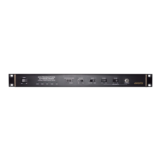
3.1. FRONT PANEL CONTROL There are currently five members of the HD9155 Series Production Afterburner family each one with a slightly different feature set. There are two basic versions of the front panels as shown below. The HD9155, HD9155-AES and HD9155Q units each have three switches, while the HD9155-Aud and HD9155Q-AUD have five switches and a headphone jack. -
Page 35: Controlling The Downconverter Mode
Model HD9155 Production Afterburner Manual 3.1.1. Controlling the Downconverter Mode The Downconverter in the HD9155 converts the 16:9 aspect ratio of the HD video to the 4:3 aspect ratio of the standard definition video in one of two modes • Letterbox •... -
Page 36: Controlling The 2:3 Pulldown
Model HD9155 Production Afterburner Manual 3.2. CONTROLLING THE 2:3 PULLDOWN When the input video to the HD9155 is 1080p/23.98sF, the HD9155 will insert 1 extra field every 4 to create a 29.97 Fps output video. This process, known as 2:3 Pulldown can be controlled by one of 3 sources. - Page 37 Model HD9155 Production Afterburner Manual CHAPTER 4: CONFIGURATION USING 9150 CONFIGWARE™ TABLE OF CONTENTS CONFIGURATION USING 9150 CONFIGWARE™................1 4.1. CONNECTING THE HD9155 TO THE 9150 CONFIGWARE™ SOFTWARE......1 4.1.1. Physical Connections ...................... 1 4.1.2. Installing the 9150 Configware™ Utility................1 4.1.3.
- Page 38 Model HD9155 Production Afterburner Manual This page left intentionally blank USING CONFIGWARE Revision 1.3...
-
Page 39: Configuration Using 9150 Configware
Model HD9155 Production Afterburner Manual CONFIGURATION USING 9150 CONFIGWARE™ The 9150 Configware™ software is used to change the HD9155’s default hardware setup for different applications. In addition to controlling the character inserter windows, VITC line placement and input time code selection, the HD9155 Systems parameters can also be controlled using the 9150 Configware™ software. -
Page 40: 9150 Configware™ Menus
Model HD9155 Production Afterburner Manual Once the installation is complete, click on the Start button and then click Programs. Select the 9150 Configware™ program group and click on the 9150 Configware™ icon. The first time you run the software you will need to configure the Communications ports on the computer that you are using to control the hardware devices. -
Page 41: Mode Menu
Model HD9155 Production Afterburner Manual 4.1.3.2. Mode Menu The 9150 Configware™ operates in one of two modes set on the Mode menu. When the software is started up it is in Offline mode. This allows the user to make changes on the configuration screens of the computer without affecting the operation of the Production Afterburner. -
Page 42: 9150 Configware™ Screens
Model HD9155 Production Afterburner Manual 4.1.4. 9150 Configware™ Screens The 9150 Configware™ has four main screens that hold the various configuration items for the Production Afterburner hardware. There are four radio buttons located under the menu bar that determine which screen you are working with. -
Page 43: Outputs Screen
Model HD9155 Production Afterburner Manual 4.1.4.2. Outputs Screen The Outputs screen is used to select what information will go into the LTC and VITC outputs, LTC: Select the source for the LTC Time and user bits. Normally this will be the ‘Video Recorder Time’ and ‘Video Recorder User Bits’. -
Page 44: Windows Screen
The Debug window can display additional debugging information on the output video. Normally this window is turned off and should only be used under direction of an Evertz Factory technician. Changing the horizontal position value for the Debug window controls the information displayed. (The window can not be moved horizontally). -
Page 45: Parameters Screen
Model HD9155 Production Afterburner Manual Virtual Slate Length:Enter the length of time in video frames that the virtual slate is to be displayed. Virtual Slate Preview: Check this box to turn on all the windows enabled for the virtual slate. This allows you to see the relative positions of the various windows when positioning other windows. - Page 46 Model HD9155 Production Afterburner Manual decimal or hexadecimal values. Clicking on the Class column heading will sort the parameter display by Class/parameter number. Clicking on the Description column heading will sort the parameter display by its description. For more information on the use of parameters see chapter 5 Page 4-8 USING CONFIGWARE Revision 1.3...
- Page 47 Model HD9155 Production Afterburner Manual CHAPTER 5: SYSTEM PARAMETERS TABLE OF CONTENTS SYSTEM PARAMETERS ........................1 5.1. 9155 PARALLEL I/O PIN FUNCTIONS ..................2 Tables Table 5-1: Class 0 - Global System Parameters HD9155's ..................1 Table 5-2: Class 15 - 9155 System Parameters ....................1 Table 5-3: Default 9155 I/O Pin Functions ......................2 Table 5-4: Alternate 9155 Input Pin Functions......................2 Table 5-5: Alternate 9155 Output Pin Functions ....................3...
- Page 48 Model HD9155 Production Afterburner Manual This page left intentionally blank SYSTEM PARAMETERS Revision 1.3...
-
Page 49: System Parameters
Model HD9155 Production Afterburner Manual SYSTEM PARAMETERS The HD9155 Production Afterburner hardware allows the user to change the default behaviour of various functions by the use of parameters. Note that the System Parameters will only affect the behaviour of the HD9155 when the front panel CONFIG switch is set to USER. -
Page 50: 9155 Parallel I/O Pin Functions
Model HD9155 Production Afterburner Manual 5.1. 9155 PARALLEL I/O PIN FUNCTIONS Parameters 0 to 2 of Class 15 control the functions of the three input pins on the Parallel I/O Connector. Parameters 3 and 4 of Class 15 control the functions of the two output pins on the Parallel I/O Connector. When the parameter value is set to zero (0) the default function of the I/O pin is selected as shown in Table 8. -
Page 51: Table 5-5: Alternate 9155 Output Pin Functions
Model HD9155 Production Afterburner Manual Parameter Signal Name Description Value DBUG_MISC_NONE Functions as default input DBUG_FRID Output toggles with picture pulldown (FRID 3:2) DBUG_FRAME 1 field active low pulse on new picture (FRAME) DBUG_SEQ_6HZ Hi = start field of output video 6Hz cycle DBUG_UPDVOFLDDB Active low Blip at start of each field DBUG_ANCERR... - Page 52 Model HD9155 Production Afterburner Manual This page left intentionally blank Page 5-4 SYSTEM PARAMETERS Revision 1.3...
- Page 53 Model HD9155 Production Afterburner Manual CHAPTER 6: TECHNICAL DESCRIPTION TABLE OF CONTENTS TECHNICAL DESCRIPTION....................... 1 6.1. SPECIFICATIONS ........................1 6.1.1. HDTV Serial Digital Video Input ..................1 6.1.2. SDTV Serial Digital Video Output..................1 6.1.3. Analog Monitor Video Output ..................1 6.1.4.
- Page 54 Model HD9155 Production Afterburner Manual 6.4.24. WIN REV (24) Firmware Revision................11 6.4.25. WIN RAM (always the last display) Ram Display............11 Tables Table 6-1: DIP Switch Functions........................... 3 Table 2: Typical File names ..........................5 Table 6-3: Debug Window Functions ........................6 TECHNICAL DESCRIPTION Revision 1.3...
-
Page 55: Technical Description
Model HD9155 Production Afterburner Manual TECHNICAL DESCRIPTION 6.1. SPECIFICATIONS 6.1.1. HDTV Serial Digital Video Input Standard: 1.485 Gb/sec HDTV Serial component digital SMPTE 292M standards supported shown in Table 2-6 software selectable or autodetect Connector: 1 BNC per IEC 169-8 Equalization: Automatic to 130m @ 1.5Gb/s with Belden 1694 or equivalent cable 6.1.2. -
Page 56: Ltc Generator
Model HD9155 Production Afterburner Manual 6.1.4. LTC Generator Standard: SMPTE 12M Frame Rate: 25 and 30 Fps nominal Connector: 3 pin male XLR type connector. Level: Adjustable, 0.5V to 4.5V p-p 6.1.5. LTC Reader Standard: SMPTE 12M Frame Rate: 24, 25 and 30 Fps nominal Connector: 3 pin female XLR type connector Level:... -
Page 57: Dip Switches
SERIAL REMOTE connector to upload new firmware from your computer. If you have a HD9155 series unit with an audio de-embedder card installed you will need to use the same procedure with the computer connected to the DE-EMBEDDER COM connector to update the de-embedder firmware. - Page 58 5 seconds then the unit will continue to boot. For example: EVERTZ 7700PB MONITOR 1.2 COPYRIGHT 1997, 1998, 1999 EVERTZ MICROSYSTEMS LTD. COLD BOOT | 6. The following is a list of possible reasons for failed communications: •...
-
Page 59: Step 3 - Uploading The New Firmware
Model HD9155 Production Afterburner Manual 6.3.3. Step 3 – Uploading the new firmware 7. Upload the “*.bin” file supplied using the X-Modem transfer protocol of your terminal program. If you do not start the upload within 10 minutes the unit’s Boot code will time out. You can restart the upgrade process by power cycling the unit. -
Page 60: Debug Window Functions
The format and content of the displays may change as the firmware evolves, but here are the current displays. Some content is intended for use only by the Evertz engineers, and is not documented. Some displays show a line of @@@@@@@@@@@@@@@@@@@ characters under specific conditions. These displays are designed to be visible on an oscilloscope that is monitoring the output video (usually in some analog form). -
Page 61: Win Hw (0) Hardware Display
Model HD9155 Production Afterburner Manual 6.4.0. WIN HW (0) Hardware Display IN: 011 DIP:11111110 SW:001 real time display of parallel port inputs MSB (2) to LSB (0), including some internal inputs IN: 011 realtime display of DIP switch, MSB (8) to LSB (1), where 0 indicates switch is in the DIP:11111110 DOWN/ON position. -
Page 62: Win Vaphase (8) Timebase Phase
Model HD9155 Production Afterburner Manual 6.4.8. WIN VAPHASE (8) Timebase Phase VPH:0.000 APH:0.000 3 video timebase phase VPH:0.000 audio timebase phase APH:0.000 pulldown reference lock counter, 0=unlocked, 3=locked 6.4.9. WIN PULLT (9) Pulldown Type PULL:K-A V-A B A(L):+0 is the pulldown indicator (A,B,C,D) of KeyKode ffff+00 frames. is the pulldown indicator (A,B,C,D) of video timecode hh:mm:ss:00 frames. -
Page 63: Win Anc Vtr (13) Anc Video Timecode
Model HD9155 Production Afterburner Manual 6.4.13. WIN ANC VTR (13) ANC Video timecode VAL:%100 F1 L23:59:59:23@24/24 source type L=RP188LTC, 1=RP188VITC1, 2=RP188VITC2, F=RP215 valid read rate as a percentage of expected read rate %100 Fields in which data is read - F12 indicates both field 1 and field 2 dynamics flags L-locked, P-play, F-forward, S-stop, R-reverse 23:59:59:23 raw, uncompensated timecode read - NOT LIKELY TO EXACTLY MATCH picture content! -
Page 64: Win Dlo (18) Data Logging Output
Model HD9155 Production Afterburner Manual 6.4.18. WIN DLO (18) Data Logging Output DLO: NOT ENABLED DLO:5 22:28:06:04@24 22:29:00:00 DLO Type Identifier 22:28:06:04 Video timecode value Video timecode counting rate 22:29:00:00 Audio timecode value 6.4.19. WIN GPI (19) GPI input frame number GPI:12:59:59:23 Video timecode of frame number where GPI input is detected going from off to on 6.4.20. -
Page 65: Win Sltc (23) Smoothed Ltc Stats
Model HD9155 Production Afterburner Manual 6.4.23. WIN SLTC (23) Smoothed LTC Stats STC:%100W1 N00E+1L23:59:59:23 STC:%100X12 N00E+1L23:59:59:23 LTC threshold set at 50% of frame. or '.' LTC threshold set at 70% of frame. valid read rate as a percentage of expected read rate %100 tolerance: number of frames of difference allowable between input LTC and smoothed tolerance delay count: counts down frames where tolerance must be 0. - Page 66 Model HD9155 Production Afterburner Manual This page left intentionally blank Page 6-12 TECHNICAL DESCRIPTION Revision 1.3...
Need help?
Do you have a question about the HD9155 Series and is the answer not in the manual?
Questions and answers