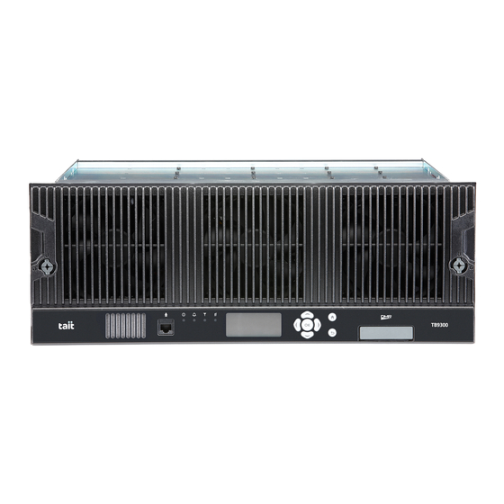
Tait TB9300 Installation And Operation Manual
Base station/repeater
Hide thumbs
Also See for TB9300:
- Installation and operation manual (146 pages) ,
- Specification manual (55 pages) ,
- Installation and operation manual (138 pages)

Subscribe to Our Youtube Channel
Related Manuals for Tait TB9300


Summary of Contents for Tait TB9300
- Page 1 TB9300 Base Station/Repeater Installation and Operation Manual MBC-00008-15 · Issue 15 · March 2017...
- Page 2 European Union. without prior written permission from Tait Limited. In China, we comply with the Measures for The word TAIT and the TAIT logo are trademarks of Administration of the Pollution Control of Electronic Tait Limited. Information Products. We will comply with...
-
Page 3: Table Of Contents
2.4 Regulatory Information ..........36 TB9300 Installation and Operation Manual... - Page 4 5.2 Connecting Your PC to the Base Station ....... . 79 TB9300 Installation and Operation Manual...
- Page 5 100W Base Station........... . .115 TB9300 Installation and Operation Manual...
- Page 6 Tait Software License Agreement ........
-
Page 7: Preface
Document Conventions The TB9300 base station has a web interface with an accordion menu on the left side of the screen. “Configure > Base Station > Channels” means click Configure in the top-level menu, then in the expanded Configure menu click Base Station, and finally click on the Channels tab on that page. -
Page 8: Associated Documentation
The characters xx represent the issue number of the documentation. Technical notes are published from time to time to describe applications for Tait products, to provide technical details not included in manuals, and to offer solutions for any problems that arise. Technical notes are available in PDF format from the Tait support website. -
Page 9: Publication Record
Added C-Band information to the tables and to Tuning the Reciter on page 61 Completely revamped the entire “Cabinet and Rack Ventilation” section. Added some missing K4 and K8 band frequency information. TB9300 Installation and Operation Manual Preface © Tait Limited March 2017... -
Page 10: Description
The ability of the base station to link stations using standard Internet Protocol communications, and to add features through software options ensures that systems designed with the TB9300 are scalable in both size and functionality. Its Ethernet interface provides built-in network connectivity. This network supports voice-over-IP in DMR networks, and remote management of all base stations via a web browser. -
Page 11: Features
Reciters (receiver/exciter modules) can be replaced without affecting the operation of other reciters in the same subrack. Rugged construction with generous heatsinks and fan-forced cooling for continuous operation from –22°F to +140°F (–30°C to +60°C). TB9300 Installation and Operation Manual Description © Tait Limited March 2017... -
Page 12: Modules
The position of a module in the subrack is defined by the socket on the subrack interconnect board to which the module is connected by the system control bus. Description TB9300 Installation and Operation Manual © Tait Limited March 2017... - Page 13 The microphone input and speaker are not used in this release of the TB9300. The reciter module comprises the Reciter receiver, exciter and digital control circuitry. The reciter provides the Ethernet interface and system inputs and outputs. TB9300 Installation and Operation Manual Description © Tait Limited March 2017...
- Page 14 AC, DC, or both AC and DC, depending on the model. The PMU also has an auxiliary DC output of 13.65VDC, 27.3VDC, or 54.6VDC, depending on the model. AC and DC PMU shown Description TB9300 Installation and Operation Manual © Tait Limited March 2017...
-
Page 15: Mechanical Assembly
PA 2 airflow separator PA 1 plastic guide rail cable retaining clip subrack interconnect board retaining clamp reciter 2 front panel fastener TB9300 Installation and Operation Manual Description © Tait Limited March 2017... - Page 16 PA in slot 3. The single PA is mounted vertically with the heatsink facing the center of the subrack. This positions the cooling fins directly behind the fan. Figure 1.2 Mechanical assembly - single 50W base station reciter 50W PA subrack Description TB9300 Installation and Operation Manual © Tait Limited March 2017...
- Page 17 Figure 1.3 Mechanical assembly - single 100W base station reciter subrack airflow duct cable retaining clip TB9300 Installation and Operation Manual Description © Tait Limited March 2017...
-
Page 18: Frequency Bands And Sub-Bands
L band L2 = 896 to 902 MHz (receive) L2 = 927 to 941 MHz (transmit) In Brazil, for K and L bands, the TB9300 is considered to be configured as a base station with retransmission of receive frequencies. Description TB9300 Installation and Operation Manual ©... -
Page 19: Applications
Applications The TB9300 is designed for operation in a Tait TN9300 DMR Tier 2 conventional radio network, a Tait TN9300 DMR Tier 3 trunked radio network, an MPT-IP network, or as an analog conventional repeater. In a DMR Tier 2 conventional network it can operate as a stand-alone repeater, or as a member of a multi-site system (under the supervision of a DMR conventional node). -
Page 20: Licenses
The central voter and satellite licences are alternatives. The base station is fully functional without them. The base stations in a Tait DMR Tier 3 Network are controlled by a node (DMR trunking controller). Tait sells three types of node: Full, Express and Access. -
Page 21: Theory Of Operation
RF From Reference Antenna Antenna Frequency AC Input System Input RF + PA Key and Output 28VDC Reciter DC Input Ethernet Interface to Network System Control Bus Front Panel TB9300 Installation and Operation Manual Description © Tait Limited March 2017... - Page 22 It performs the air interface signal processing for digital DMR operation, gives the base station an identity as a network element, and provides the physical connections for the Ethernet and system interfaces. Description TB9300 Installation and Operation Manual © Tait Limited March 2017...
-
Page 23: Signal Paths
Offline mode. This takes the base station out of service. However, the front panel is still operational and can be used in the normal way. TB9300 Installation and Operation Manual Description © Tait Limited March 2017... -
Page 24: Intermodule Communications
Intermodule communication paths Reciter 1 PA 1 I C Current Source Fan 3: Fan 1: Reciters User Controls Fan 2: Front Panel Subrack Interconnect Board Reciter 2 PA 2 Description TB9300 Installation and Operation Manual © Tait Limited March 2017... -
Page 25: Power Management And Distribution
The outputs from both the AC and DC high power converters are added together and fed to the modules via the high-current outputs. The auxiliary output is also tapped off this summed output. TB9300 Installation and Operation Manual Description © Tait Limited March 2017... - Page 26 Figure 1.8 Subrack power distribution Single Aux. DC Subrack Board Front Reciter Panel Dual Aux. DC Subrack Board Front PA 1 PA 2 Reciter 1 Reciter 2 Panel Description TB9300 Installation and Operation Manual © Tait Limited March 2017...
-
Page 27: Pmu Operation On Dc Input
These limits will not be reached under normal operation conditions, but are provided as “fail-safe” measures to protect the battery from deep discharge. They also remove the need for low-voltage disconnect modules. TB9300 Installation and Operation Manual Description © Tait Limited March 2017... - Page 28 The information in this table is extracted from the Specifications Manual. Refer to the latest issue of this manual for the most up-to-date and complete PMU specifications. b. Using the base station’s web interface. Description TB9300 Installation and Operation Manual © Tait Limited March 2017...
- Page 29 Figure 1.9 PMU alarm thresholds and voltage limits when operating on DC TB9300 Installation and Operation Manual Description © Tait Limited March 2017...
-
Page 30: Front Panel Fans
2 minutes on, 8 minutes off 6A–8A 2 minutes on, 5 minutes off 8A–12A 3 minutes on, 3 minutes off 12A–14A 4 minutes on, 1 minute off always on >149°F (65°C) –– always on Description TB9300 Installation and Operation Manual © Tait Limited March 2017... -
Page 31: General Safety And Regulatory Information
The PMU should be serviced only by qualified technicians. There are no user-replaceable parts inside. If the PMU is damaged and does not function properly, stop the module safely and contact your regional Tait office immediately. All servicing should be carried out only when the PMU is powered through a mains isolating transformer of sufficient rating. -
Page 32: Ac Power Connection
PMU and PA can reach temperatures of up to +176°F (+80°C). 2.1.6 LED Safety (EN60825-1) This equipment contains Class 1 LED Products. General Safety and Regulatory Information TB9300 Installation and Operation Manual © Tait Limited March 2017... -
Page 33: Proximity To Rf Transmissions / A Proximité Des Émissions Rf
OET numéro 65 (47CFR 1.1310) IEEE C95.1 2005: Norme pour les niveaux de sécurité compatibles avec l'exposition des personnes aux champs électromagnétiques de radiofréquence 3kHz à 300GHz TB9300 Installation and Operation Manual General Safety and Regulatory Information © Tait Limited March 2017... -
Page 34: Equipment Safety
ESD S20.20-1999 or BS EN 100015-4 1994. Figure 2.1 Typical antistatic bench set-up common point ground (building ground or mains ground) dissipative rubber bench mat conductive wrist strap General Safety and Regulatory Information TB9300 Installation and Operation Manual © Tait Limited March 2017... -
Page 35: Anti-Tampering Devices
The humidity should not exceed 95% relative humidity through the specified operating temperature range. 2.3.3 Dust and Dirt For uncontrolled environments, the level of airborne particulates must not exceed 100µg/m TB9300 Installation and Operation Manual General Safety and Regulatory Information © Tait Limited March 2017... -
Page 36: Regulatory Information
2.4.4 Unauthorized Modifications Any modifications you make to this equipment which are not authorized by Tait may invalidate your compliance authority’s approval to operate the equipment. The manufacturer is not responsible for any radio or TV interference caused by unauthorized modifications to this equipment. Such modifications could void the user’s authority to operate the equipment. -
Page 37: Health, Safety And Electromagnetic Compatibility In Europe
EU/EEA, and will require a licence to operate in each member state. You can download the formal Declaration of Conformity from Declaration of Conformity www.taitradio.com/eudoc. TB9300 Installation and Operation Manual General Safety and Regulatory Information © Tait Limited March 2017... -
Page 38: Operation
Operation This section describes the user controls and indicator LEDs on the front panel and on the base station modules. Operation TB9300 Installation and Operation Manual © Tait Limited March 2017... -
Page 39: Front Panel
One or more faults are present. On (steady) A base station is in Offline mode, and no faults are present. A base station is in Online mode, and no faults are present. TB9300 Installation and Operation Manual Operation © Tait Limited March 2017... - Page 40 Moves the cursor up one line in the IP address screen. When the top line is reached, pressing again returns to the previous menu. Unlike a computer keyboard, the keys do not auto-repeat. Each action requires a separate key-press. Operation TB9300 Installation and Operation Manual © Tait Limited March 2017...
- Page 41 When the contrast is set to the required level, press OK to save the changes and exit the menu. TB9300 Installation and Operation Manual Operation © Tait Limited March 2017...
- Page 42 Modules Reciter 1 View Reciter 1 Address 172.025.198.043 Front Panel Edit Reciter 1 Address MASK: 255.255.000.000 172.025.002.251 Edit Reciter 1 Address 172.025.198.043 MASK: 255.255.000.000 172.025.002.251 Front Panel Contrast Contrast Operation TB9300 Installation and Operation Manual © Tait Limited March 2017...
-
Page 43: Module Indicator Leds And Switches
- the reciter is powered up flashing red - one or more alarms have been generated; you can use the web interface to find out more details about the alarms. TB9300 Installation and Operation Manual Operation © Tait Limited March 2017... - Page 44 These LEDs provide the following information about the state of the reciter: steady amber - the Ethernet interface is connected flashing green - data is being transmitted across the Ethernet interface. Operation TB9300 Installation and Operation Manual © Tait Limited March 2017...
- Page 45 The alarm LED will flash whenever an alarm is generated, whether or not this alarm has been disabled via the web interface. TB9300 Installation and Operation Manual Operation © Tait Limited March 2017...
-
Page 46: Pmu
Even when the DC converter is off, the DC input is still connected to its power circuitry. The switch is recessed to prevent the DC module being accidentally switched off. Operation TB9300 Installation and Operation Manual © Tait Limited March 2017... - Page 47 The alarm LED will flash whenever an alarm is generated, whether or not this alarm has been disabled via the web interface. TB9300 Installation and Operation Manual Operation © Tait Limited March 2017...
-
Page 48: Installation
Installation This chapter provides information on the site requirements for your TB9300 equipment and also describes how to install the base station in a standard 19 inch rack or cabinet. If this is your first time installing a TB9300 base station, we recommend that you read the entire chapter before beginning the actual installation. -
Page 49: Before You Begin
(e.g. for servicing purposes). 4.1.4 Ambient Temperature Sensor The ambient temperature reading for the base station is provided by the temperature sensor located on the front panel circuit board. TB9300 Installation and Operation Manual Installation © Tait Limited March 2017... -
Page 50: Cabinet And Rack Ventilation
The maximum ambient temperature at the base station front panels must not exceed +140°F (+60°C). Installation TB9300 Installation and Operation Manual © Tait Limited March 2017... - Page 51 Figure 4.1 Typical cabinet ventilation requirements top view (20cm) side view front view ( 17.5cm) ventilation slots airflow entry blanking panels airflow exit path TB9300 Installation and Operation Manual Installation © Tait Limited March 2017...
-
Page 52: Unpacking And Moving The Subrack
Cut the tape securing the flaps at the top of the carton and fold them flat against the sides Rotate the carton carefully onto its side and then onto its top ensuring that none of the flaps is trapped underneath. Installation TB9300 Installation and Operation Manual © Tait Limited March 2017... - Page 53 Packaging it according to your local recycling methods. The foam cushions are CFC- and HCFC-free and may be burnt in a suitable waste-to-energy combustion facility, or compacted in landfill. TB9300 Installation and Operation Manual Installation © Tait Limited March 2017...
-
Page 54: Identifying The Equipment
Identifying the Equipment You can identify the model and hardware configuration of the TB9300 modules by referring to the product code printed on labels at the rear of each module. The meaning of each character in the product code is explained in the tables below. - Page 55 The actual frequency coverage in this band when used with a K4-band TB9300 reciter is 762MHz to 776MHz and 850MHZ to 870MHz. The actual frequency coverage in this band when used with a K8-band TB9300 reciter is 757MHz to 758MHz.
-
Page 56: Initial Setting Up
One or more fans may operate, depending on the temperature of the modules. Installation TB9300 Installation and Operation Manual © Tait Limited March 2017... - Page 57 PMU mains failure requires a DC backup supply Diagnose > Subsystems > PMU Control Tests fan operation checks the operation of each fan Diagnose > Subsystems > Fan Tests individually TB9300 Installation and Operation Manual Installation © Tait Limited March 2017...
-
Page 58: Working With Configurations
You should also back up the configuration before downgrading to a dif- ferent software release. Note that if you downgrade and then upgrade software, configuration values for new features may become default. Installation TB9300 Installation and Operation Manual © Tait Limited March 2017... -
Page 59: Recommended Configuration Settings
Disable the “PMU not detected” alarm on base station 2 (Configure > Alarms > Control > PMU). Disable the “FP not detected” alarm on base station 2 (Configure > Alarms > Control > Front panel). TB9300 Installation and Operation Manual Installation © Tait Limited March 2017... -
Page 60: Restricted Port Numbers
Knowledge of the password could be used to render the equipment inoperable, for example by deleting files. If you are concerned about the security risk that this poses, change the password. If Tait provides support services, they may need to know the password. -
Page 61: Tuning The Reciter
Identifying the B-band and C-band receiver front end helical filters B2: 146 to 156MHz B3: 159 to 174MHz B2: 136 to 146 MHz B3: 148 to 159 MHz C3: 216 to 215 MHz TB9300 Installation and Operation Manual Installation © Tait Limited March 2017... - Page 62 Remove the reciterfrom the subrack and reconnect the system control bus cable to power up the module. Tait can provide extender cables (TBC Reciter Power Cables) to enable tuning with a subrack or from a bench power supply. To order these, the part number is T01-01150-0001.
- Page 63 RSSI level of the new frequency is more than 1dB lower than the RSSI level of the previously set frequency. Tait can provide extender cables (TBC Reciter Power Cables) to enable tuning with a subrack or from a bench power supply. To order these, the part number is T01-01150-0001.
- Page 64 The G-band, K-band and L-band reciters do not require tuning. Electronically Tuned Reciters 1. Included in the TBA0ST2 tool kit. Also available separately as part num- ber 937-00013-00. Installation TB9300 Installation and Operation Manual © Tait Limited March 2017...
-
Page 65: Installing The Base Station On Site
8mm AF spanner for the SMA connectors, and the subrack ground connector. You can also obtain the TBA0ST2 tool kit from your regional Tait office. It contains the basic tools needed to install, tune, and service the base station. -
Page 66: Mounting The Subrack
M6 (0.25in) screw, flat and spring washer in each of the four main mounting holes , as shown in Figure 4.5. If you need extra mounting security, additional mounting holes provided at the rear of the subrack for auxiliary support brackets. Installation TB9300 Installation and Operation Manual © Tait Limited March 2017... - Page 67 14.7 in (373.5 mm) 18.3 in (465.1 mm) 14.37 in (365 mm) 4 in 5.25 in 6.96 in 0.42 in (101.6 mm) (133.4 mm) (176.8 mm) (10.6 mm) 0.26 in (6.6 mm) TB9300 Installation and Operation Manual Installation © Tait Limited March 2017...
- Page 68 TBAA03-13 bracket fitted in a typical Tait cabinet . If you are not using the Tait cabinet, you may have to make your own brackets to suit your installation. Figure 4.7 Auxiliary support bracket Notice You must fit the auxiliary support brackets if you intend to transport a cabinet fitted with a fully built-up base station.
- Page 69 We recommend that you fit the supplied covers to the DC terminals to protect against accidental shorts. Figure 4.8 DC power cabling secure the cables to the cabinet to support their weight TB9300 Installation and Operation Manual Installation © Tait Limited March 2017...
Need help?
Do you have a question about the TB9300 and is the answer not in the manual?
Questions and answers