Table of Contents
Advertisement
PRODUCT MANUAL
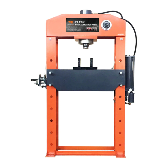
75 TON HYDRAULIC SHOP PRESS
AIR MOTOR AND MANUAL PUMP OPERATION
MODEL:TMG-SP75
Please read the product manual completely before assembly
Check against the parts list to make sure all parts are received
Wear proper safety goggles or other protective gears while in assembly
Missing parts or questions on assembly?
Please call: 1-877-761-2819 or email: cs@tmgindustrial.com
Do not return the product to dealer, they are not equipped to handle your requests
WWW.TMGINDUSTRIAL.COM
Toll Free:1-877-761-2819
Advertisement
Table of Contents

Related Manuals for TMG TMG-SP75


Summary of Contents for TMG TMG-SP75
- Page 1 PRODUCT MANUAL 75 TON HYDRAULIC SHOP PRESS AIR MOTOR AND MANUAL PUMP OPERATION MODEL:TMG-SP75 Please read the product manual completely before assembly Check against the parts list to make sure all parts are received Wear proper safety goggles or other protective gears while in assembly Missing parts or questions on assembly? Please call: 1-877-761-2819 or email: cs@tmgindustrial.com...
-
Page 2: Intended Use
Typical applications include installation and removal of alternator and power steering pump bearings, axle bearings, transmission bearings, seals, u-joints and many other jobs. TECHNICAL SPECIFICATIONS Description Item TMG-SP75 Capacity 75 Ton Working Press(PSI) 100-125 Air Inlet Size(in.ZG) Work Range(in.)... -
Page 3: General Safety Rules
GENERAL SAFETY RULES WARNING: Read and understand all instructions. Failure to follow all instructions listed below may result in serious injury. CAUTION: Do not allow persons to operate or assemble this Shop Press until they have read this manual and have developed a thorough understanding of how the Shop Press works. WARNING: The warnings, cautions, and instructions discussed in this instruction manual cannot cover all possible conditions or situations that could occur. -
Page 4: Safety Markings
DO NOT OPERATE OR REPAIR THIS EQUIPMENT WITHOUT READING THIS MANUAL. To maintain the Shop Press and user safety, the responsibility of the owner is to read and follow these instructions. Inspect the service shop press for proper operation and function. Keep instructions readily available for equipment operators. - Page 5 PLEASE READ THESE INSTRUCTIONS CAREFULLY. NOTE THE SAFETY INSTRUCTIONS AND WARNING. USE THE PRODUCT CORRECTLY AND WITH CARE FOR THE PURPOSE OF WHICH IT IS INTENDED. FAILURE TO DO SO MAY CAUSE DAMAGE TO PROPERTY AND/OR SERIOUS PERSONAL INJURY. PLEASE KEEP THIS INSTRUCTION MANUAL SAFE FOR FUTURE USE. We’ve done all we can to assure this press offers the utmost in safety, but you have to do your part.
- Page 6 ASSEMBLY All numbers in parenthesis ()refer to the index number from the parts breakdown. 1.Attach the two base support sections (28) to the base with bolt (29),washer (14),and nuts (13). 2.Attach the hydraulic air pump (19) to the right frame (1) with washer (16) and bolt (18). Ensure that the hydraulic air pump (19) is securely installed.
- Page 7 3. Then install winch (32) to the L-bracket (12) with washer (16), bolt (18) and nut (17). 4. Attach the L-bracket (12) to the left frame (1) with washer (16),bolt (15) and nut (17). 5. Raise the joined press bed frame (2) to the desired height and insert the bed frame pins (3) into the holes on the frames (1).
- Page 8 6.Place the bolster plates (10) the bed frame (2). 7.Verify that all bolts and screws have been tightened. 8.The press is now ready for use. W W W . T M G I N D U S T R I A L . C O M P 8 / 2 0 T o l l F r e e : 1 - 8 7 7 - 7 6 1 - 2 8 1 9...
-
Page 9: Before Use
BEFORE USE 1.Before using this product, read the owner's manual completely and familiarize yourself thoroughly with the product and the hazards associated with its improper use. 2.Perform the air purge procedure. (The new product can’t perform this operation, See page 13 of instructions) 3.Inspect before each use. - Page 10 3. Place work piece on the bed frame or pressing block, use every precaution necessary to ensure safety and to prevent accidents. Position work piece in a manner which not allow it to inadvertently fall from the bed frame or pressing block. 4.Close the release valve by turning it clockwise until it is firmly closed.
- Page 11 5.Align ram and work piece to ensure center-loading. Do not overload work piece. 6.When work is completed, stop pumping the handle(or release the trigger).Slowly turn the release Valve counter-clockwise in small increments until ram is free from work piece. 7.Once ram has fully retracted, remove workplace from bed frame. Cautiously remove work piece from press.
-
Page 12: Maintenance Instructions
MAINTENANCE INSTRUCTIONS If you use and maintain your equipment properly, it will give you many years of service. Follow the Maintenance instructions carefully to keep your equipment in good working condition. Never perform any Maintenance on the equipment while it is under a load. Inspection You should inspect the product for damage, wear, broken or missing parts(e.g.: pins) and that all Components function before each use. - Page 13 TO ADD OIL: The hydraulic cylinder assembly contains hydraulic fluid that must be kept at approximately 80% full at all times for proper operation. To check the oil level and to fill remove oil filler Plug 1. Fully retract the hydraulic ram. 4.Screw the oil plug.
- Page 14 To Replace Oil: 5. Fill the oil case. 1.Position the pump in the vertical position and KEEP DIRT AND OTHER MATERIAL fully retract the hydraulic ram. CLEAR WHEN POURING. 2.Open release valve by turning handle counter-clockwise. 6. Screw the oil plug. 3.Remove the oil plug.
-
Page 15: Additional Warnings
ADDITIONAL WARNINGS: DO NOT USE MOTOR OIL IN THE JACK. ONLY USE ANTI-FOAMING JACK OIL. ALWAYS USE A GOOD GRADE HYDRAULIC JACK OIL. DO NOT USE HYDRAULIC BRAKE FLUID, AALCOHOL,GLYCERINE,DETERGENT,MOTOR OIL OR DIRTY OIL. USE OF A NON-RECOMMENDED FLUID CANCAUSE DAMAGE TO A JACK. USE OF A NON-RECOMMENDED FLUID CANCAUSE DAMAGE TO A JACK. -
Page 16: Assembly Diagram
ASSEMBLY DIAGRAM W W W . T M G I N D U S T R I A L . C O M P 1 6 / 2 0 T o l l F r e e : 1 - 8 7 7 - 7 6 1 - 2 8 1 9... -
Page 17: Parts List
PARTS LIST Index# Part No. Description Qty. Frame Parts Middle Groove Set Bed Frame Pin Long Roller Bolt Round Sleeve Roller Roller Arbor Circlip Pressure Gauge Bolster Plates Press Cylinder Part L-Bracket Nut-M12 Washer-12 Bolt-M10x35 Washer-10 Nut-M10 Bolt-M10x25 Press Pump Part Pressure Gauge Joint Joint Bolt Joint Nut... -
Page 18: Pump Assembly Diagram
PUMP ASSEMBLY DIAGRAM W W W . T M G I N D U S T R I A L . C O M P 1 8 / 2 0 T o l l F r e e : 1 - 8 7 7 - 7 6 1 - 2 8 1 9... -
Page 19: Pump Parts List
PUMP PARTS LIST Index# Part No. Description Qty. Cover Sole plate O-Ring Reservoir Stay Bar Washer-10 Nut-M10 Ball-4 Ball Seat Spring Safety Valve- 7.3x2x22 Adjustable Pressure Bolt Safety Valve Bolt O-Ring-7.7x1.9 Release Valve Ball-6 Spring High Pressure Bolt Nylon Washer-15x10x2 Right-Angle Connect Ring-18x9x1 Air Pump... - Page 20 RAM ASSEMBLY DIAGRAM RAM PARTS LIST Index# Part No. Description Qty. Cylinder Assembly Piston Rod O-Ring-63.5x3.55 Piston Head Y-Ring-125x110x12 Spring Extension Spring Blot Brass Washer-12x18x1.5 Bolt-12x90 Nuts Spring Pin-10x100 Piston Nuts Nuts Ram Bolt Straight Connect W W W . T M G I N D U S T R I A L . C O M P 2 0 / 2 0 T o l l F r e e : 1 - 8 7 7 - 7 6 1 - 2 8 1 9...
Need help?
Do you have a question about the TMG-SP75 and is the answer not in the manual?
Questions and answers