Table of Contents
Advertisement
V2021.03.01
PRODUCT MANUAL
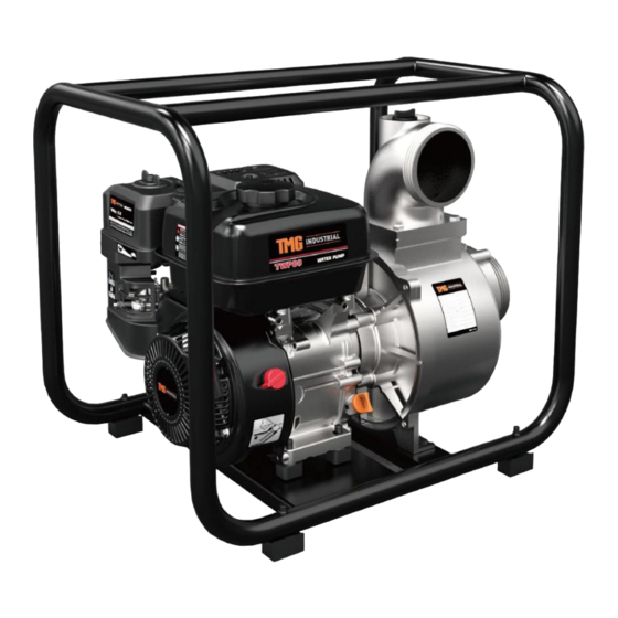
GAS ENGINE WATER PUMP
MODEL: TMG-50TWP
TMG-80TWP
TMG-100TWP
Please read the product manual completely before assembly
Check against the parts list to make sure all parts are received
Wear proper safety goggles or other protective gears while in assembly
Missing parts or questions on assembly?
Please call: 1-877-761-2819 or email: cs@tmgindustrial.com
Do not return the product to dealer, they are not equipped to handle your requests
WWW.TMGINDUSTRIAL.COM
TOLL FREE:1-877-761-2819
Advertisement
Table of Contents

Related Manuals for TMG TMG-50TWP


Summary of Contents for TMG TMG-50TWP
- Page 1 V2021.03.01 PRODUCT MANUAL GAS ENGINE WATER PUMP MODEL: TMG-50TWP TMG-80TWP TMG-100TWP Please read the product manual completely before assembly Check against the parts list to make sure all parts are received Wear proper safety goggles or other protective gears while in assembly Missing parts or questions on assembly? Please call: 1-877-761-2819 or email: cs@tmgindustrial.com...
-
Page 2: Table Of Contents
CONTENTS 1. PUMP SAFETY......................3 2. COMPONENTS & CONTROL LOCATIONS............5 3. CONTROLS........................6 4. CHECK BEFORE OPERATION................8 5. OPERATION........................12 6. STARTING THE ENGINE..................15 7. STOPPING THE ENGINE..................17 8. MAINTENANCE......................18 9. TRANSPORTING/STORAGE...................25 10. TROUBLESHOOTING....................29 11. SPECIFICATIONS......................31 12. CONSUMER INFORMATION................... 32 13. -
Page 3: Pump Safety
1. PUMP SAFETY Your safety and the safety of others are very important. And using this water pump safely is an important responsibility. To help you make informed decisions about safety, we have provided operating procedures and other information on labels and in this manual. This information alerts you to potential hazards that could hurt you or others. - Page 4 Always make a pre-operation inspection before you start the engine. You may prevent an accident or equipment damage. Most accidents can be prevented if you follow all instructions in this manual and on the pump. The most common hazards are discussed below, along with the best way to protect yourself and others.
-
Page 5: Components & Control Locations
2. COMPONENTS & CONTROL LOCATIONS DISCHARGE PORT THROTTLE LEVER FUEL FILLER CHOKE LEVER FUEL VALVE LEVER STARTER GRIP OIL FILLER CAP/DIPSTICK IGNITION SWITCH FRAME PRIMING WATER FILLER CAP AIR CLEANER MUFFLER SUCTION PORT PUMP DRAIN CAP OIL DRAIN PLUG WWW.TMGINDUS TRIAL.COM P05/50 Toll Free :1-877-761-2819... -
Page 6: Controls
3. CONTROLS Read and understand this manual. Know what the controls do and how to operate them. Familiarize yourself with the pump and its operation before you begin pumping. Know what to do in case of emergencies. Fuel Valve Lever The fuel valve opens and closes the passage between the fuel tank and the carburetor. - Page 7 Choke Lever The choke lever opens and closes the choke valve in the carburetor. The CLOSED position enriches the fuel mixture for starting a cold engine. The OPEN position provides the correct fuel mixture for operation after starting, and for restarting a warm engine. CHOKE LEVER OPEN CLOSE...
-
Page 8: Check Before Operation
4. CHECK BEFORE OPERATION Be sure of what you are pumping. This pump is designed to pump only fresh water that is not intended for human consumption. For your safety, and to maximize the service life of your equipment, it is very important to take a few moments before you operate the pump to check its condition. - Page 9 Check that the hose connectors and clamps are securely installed (see pages 13 & 14). Check that the strainer is in good condition and is installed on the suction hose (see page 13). CHECK ENGINE OIL LEVEL Check the engine oil level with the engine stopped and in a level position. 1.
- Page 10 Remove the air cleaner cover and inspect the filter. Clean or replace dirty filter elements. Always replace damaged filter elements. If equipped with an oil-bath air cleaner, also check the oil level. Reinstall the air filter and air cleaner cover. Be sure all the parts shown below are in place.
- Page 11 MAXIMUM FUEL LEVEL Do not fill above the shoulder of the fuel strainer (maximum fuel level). FUEL RECOMMENDATIONS Use unleaded gasoline with a pump octane rating of 86 or higher. These engines are certified to operate on unleaded gasoline. Unleaded gasoline produces fewer engine and spark plug deposits and extends exhaust system life.
-
Page 12: Operation
5. OPERATION SAFE OPERATING PRECAUTIONS To safely realize the full potential of this pump, you need a complete understanding of its operation and a certain amount of practice with its controls. Before operating the pump for the first time, please review the IMPORTANT SAFETY INFORMATION on page 3 and the chapter titled CHECK BEFORE OPERATION. - Page 13 SUCTION HOSE INSTALLATION Use a commercially available hose and hose connector with the hose clamp provided with the pump. The suction hose must be reinforced with a non- collapsible wall or braided wire construction. Do not use a hose smaller than the pump’s suction port size. Minimum hose size: WP25(25mm),WP50.CP50.HP50(50mm),WT80.WP80(80mm),WP100(100mm).
- Page 14 DISCHARGE HOSE INSTALLATION Use a commercially available hose and hose connector, and clamp provided with the pump. HOSE CONNECTOR It is best to use a short, large-diameter hose, because that will reduce fluid HOSE CLAMP friction and improve pump output. A long or small-diameter hose will increase fluid friction and reduce pump output.
-
Page 15: Starting The Engine
6. STARTING THE ENGINE 1. Prime the pump (see page 14). 2. Move the fuel valve lever to the ON position. 3. To start a cold engine, move the choke lever to the CLOSED position. To restart a warm engine, leave the choke lever in the OPEN position. CHOKE LEVER CLOSED 4. - Page 16 6. Pull the recoil starter grip lightly until resistance is felt, then pull it briskly. Do not allow the recoil starter grip to snap back against the engine. Return it gently to prevent damage to the starter. RECOIL STARTER GRIP 7.
-
Page 17: Stopping The Engine
7. STOPPING THE ENGINE To stop the engine in an emergency, simply turn the ignition switch to the OFF position. Under normal conditions, use the following procedure. 1. Move the throttle lever to the SLOW position. THROTTLE LEVEL SLOW 2. Turn the ignition switch to the OFF position. IGNITION SWITCH 3. -
Page 18: Maintenance
8. MAITENANCE THE IMPORTANCE OF MAINTENANCE Good maintenance is essential for safe, economical, and trouble-free operation. It will also help reduce air pollution. Improperly maintaining this pump, or failing to correct a problem before operation, can cause a malfunction in which you can be seriously hurt or killed. - Page 19 Safety Precautions Make sure the engine is off before you begin any maintenance or repairs. This will eliminate several potential hazards: -Carbon monoxide poisoning from engine exhaust. Be sure there is adequate ventilation whenever you operate the engine. -Burns from hot parts. Let the engine and exhaust system cool before touching.
- Page 20 REFUELING With the engine stopped and on a level surface, remove the fuel tank cap and check the fuel level. Refill the tank if the fuel level is low. MAXIMUM FUEL LEVEL Refuel in a well-ventilated area before starting the engine. If the engine has been running, allow it to cool.
- Page 21 ENGINE OIL CHANGE Drain the used oil while the engine is warm. Warm oil drains quickly and completely. 1. Place a suitable container below the engine to catch the used oil, and then remove the oil filler cap/dipstick, drain plug and sealing washer. 2.
- Page 22 SAE Viscosity Grades AMBIENT TEMPERATURE The SAE oil viscosity and service classification are in the API label on the oil container. We recommend that you use API SERVICE category SJ oil. The recommended operating range of this pump is 23 °F to 104 °F ( -5 °Cto 40 °C).
- Page 23 3. Inspect the spark plug. Replace it if the electrodes are worn, or if the insulator is cracked or chipped. SPARK PLUG WRENCH 0.70-0.80mm SEALING WASHER SPARK PLUG 4. Measure the spark plug electrode gap with a suitable gauge. Correct the gap if necessary, by carefully bending the side electrode.
- Page 24 1. Remove the two 8 mm nuts, and remove the muffler. 2. Remove the four 5 mm screws, and remove the muffler protector from the muffler. 3. Remove the 4 mm screw from the spark arrester, and remove the spark arrester from the muffler.
-
Page 25: Transporting/Storage
9. STORAGE/TRANSPORTING STORAGE PREPARATION Proper storage preparation is essential for keeping your pump troublefree and looking good. The following steps will help to keep rust and corrosion from impairing your pump’s function and appearance, and will make the engine easier to start when you use the pump again. - Page 26 Fuel Gasoline will oxidize and deteriorate in storage. Old gasoline will cause hard starting, and it leaves gum deposits that clog the fuel system. If the gasoline in your engine deteriorates during storage, you may need to have the carburetor and other fuel system components serviced or replaced.
- Page 27 2. Remove the carburetor drain bolt and sediment cup, and then move the fuel valve lever to the ON position. FUEL VALVELEVEL SEDIMENTCAP 3. After all the fuel has drained into the container, reinstall the drain bolt and sediment cup. Tighten them securely. STORAGE PR PROCEDURE 1.
- Page 28 STORAGE PRECAUTIONS If your pump will be stored with gasoline in the fuel tank and carburetor, it is important to reduce the hazard of gasoline vapor ignition. Select a well-ventilated storage area away from any appliance that operates with a flame, such as a furnace, water heater, or clothes dryer.
-
Page 29: Troubleshooting
10. TROUBLESHOOTING ENGINE Engine Will Not Start Possible Cause Correction Move fuel valve lever to Fuel valve OFF. ON position. Move choke lever to 1.Check control Choke open. CLOSED position unless positions. engine is warm. Turn ignition switch to Ignition switch OFF. Out of fuel. - Page 30 PUMP No Pump Output Possible Cause Correction 1.Check pump chamber. Pump not primed. Prime the pump (p.14). Hose collapsed, cut or Replace suction hose (p. punctured. 13). Sink the strainer and Strainer not completely the end of a suction underwater. hose completely underwater.
-
Page 31: Specifications
11. SPECIFICATIONS Model TMG-50TWP TMG-80TWP TMG-100TWP Dia. of discharge port(mm) Dia. of suction port (mm) Lift(m) Discharge capacity(m Suction(m) Engine model AP168FB AP170F SC230 Displacement (cc) Rated speed(rpm) 3600 3600 3600 Oil capacity(L) Gasoline capacity(L) Tuneup Spark plug gap See page 22. - Page 32 12. TECHNICAL & CONSUMER INFORMATION Carburetor Modification for High Altitude Operation At high altitude, the standard carburetor air-fuel mixture will be too rich. Performance will decrease, and fuel consumption will increase. A very rich mixture will also foul the spark plug and cause hard starting. Operation at an altitude that differs from that at which this engine was certified, for extended periods of time, may increase emissions.
- Page 33 You may use gasoline containing up to 10% ethanol by volume. Gasoline containing ethanol may be marketed under the name ‘‘Gasohol’’. MTBE (methyl tertiary butyl ether) 15% by volume You may use gasoline containing up to 15% MTBE by volume. METHANOL——(methyl or wood alcohol) 5% by volume You may use gasoline containing up to 5% methanol by volume as long as it also contains cosolvents and corrosion inhibitors to...
- Page 34 Problems That May Affect Emissions If you are aware of any of the following symptoms, have your engine inspected and repaired by your servicing dealer. Hard starting or stalling after starting. · Rough idle. · Misfiring or backfiring under load. ·...
-
Page 35: Consumer Information
Control Warranty for additional information. Descriptive Term Applicable to Emission Durability Period 50 hours (0-65 cc) Moderate 125 hours (greater than 65 cc) 125 hours (0-65 cc) Intermediate 250 hours (greater than 65 cc) 300 hours (0-65 cc) Extended 500 hours (greater than 65 cc) The Air Index Information hang tag must remain on the pump until it is sold. -
Page 36: Explosion Diagram And Parts Lise
13.EXPLOSION DIAGRAM AND PARTS LIST TMG-50TWP EXPLOSION DIAGRAM Main Explosion Diagram Description Part Engine 20260-04705-00 Frame Components 20090-01176-00 Pump 20100-00316-01 Hex Wrench 70003-00858-00 Open Spanner 70003-00909-00 Toolkit 70009-00313-00 Shock Absorbing Rubber 34030-00066-00 Bolt Flange 30101-00461-00 Nut Flange 30125-00003-00 Bolt Flange... - Page 37 Engine Explosion Diagram WWW.TMGINDUS TRIAL.COM P37/50 Toll Free :1-877-761-2819...
- Page 38 Part Description Part NO. Description Bolt,M6×12 Bolt,M10×15 30101-00070-00 30101-00487-00 Cover Comp.Head Washer 20021-00009-00 30136-00078-00 Gasket,Head Cover Crankcase 33048-00031-00 34011-00006-00 Nut,Valve Adjusting Engine Oil Sensor 30121-00034-00 33247-00005-00 Rocker Shaft Bolt,M6×16 33048-00005-00 30101-00342-00 Rocker Arm Washer 34019-00003-00 30136-00092-00 Bolt Valve Shaft,Governor 30110-00032-00 34026-00003-01 Rotator,Valve Pin, Lock...
- Page 39 Pump Explosion Diagram WWW.TMGINDUS TRIAL.COM P39/50 Toll Free :1-877-761-2819...
- Page 40 Description Part NO. Description Part 70010-00243-00 Seat Assy 70010-01174-00 Outlet Port 30152-00058-00 O Type Sealing Ring 33275-00013-00 Pressing Cap Gasket 30136-00135-00 Al Flat Washer 70010-00394-00 Transfer Pipe Joint 30101-00468-00 Bolt,Flange 70003-01321-00 Wrench Pressing Cap 70010-00109-00 Mechanical Seal 33048-00085-00 Outlet Gasket 70010-00001-00 Impeller 39999-00011-00...
- Page 41 TMG-80TWP EXPLOSION DIAGRAM Main Explosion Diagram Description Part Engine 20260-03165-01 Frame Components 20090-01063-00 Pump 20100-00257-00 Hex Wrench 70003-00858-00 Open Spanner 70003-00909-00 Tool Bag 70009-00313-00 Shock Absorbing Rubber 34030-00066-00 Bolt,Flange 30114-00018-00 Nylon Nut 30128-00011-00 Bolt,Flange 30101-00461-00 Nut, Flange 30125-00003-00 WWW.TMGINDUS TRIAL.COM...
- Page 42 Engine Explosion Diagram WWW.TMGINDUS TRIAL.COM P42/50 Toll Free :1-877-761-2819...
- Page 43 Part NO. Description Part NO. Description Bolt,M6×12 Bolt,M10×15 30101-00070-00 30101-00487-00 Cover Comp.Head Washer 20021-00009-00 30136-00078-00 Gasket,Head Cover Crankcase 33048-00024-00 34011-00009-00 Nut,Valve Adjusting Engine Oil Sensor 30121-00034-00 33247-00005-00 Rocker Shaft Bolt,M6×16 30134-00005-00 30101-00342-00 Rocker Arm Washer 34019-00003-00 30136-00092-00 Bolt Valve Shaft,Governor 30110-00032-00 34026-00003-01 Ratator,Valve...
- Page 44 Pump Explosion Diagram Pump Explosion Diagram WWW.TMGINDUS TRIAL.COM P44/50 Toll Free :1-877-761-2819...
- Page 45 Part NO. Description Part NO. Description 70010-00172-01 Pump Side Cover 70010-00238-00 Plug Screw 30152-00059-00 O Ring 70010-01172-00 Outlet Port 30136-00135-00 Al Flat Washer 33275-00015-00 Pressing Cap Gasket 30101-00468-00 Bolt 70003-00851-00 Wrench Pressing Cap 70010-00004-00 Mechanical Seal 33048-00129-00 Outlet Gasket 70010-00003-00 Impeller 39999-00413-00 Pump Case...
- Page 46 TMG-100TWP EXPLOSION DIAGRAM Main Explosion Diagram Part NO. Description Engine 20090-01177-00 Frame Components 30114-00019-00 Pump 34030-00066-00 Hex Wrench 70003-00858-00 Open Spanner 70003-00909-00 Tool Bag 70009-00313-00 Bolt Flange 30101-00370-00 Flat Washer 30136-00123-00 Nylon Nut 30128-00014-00 Shock Absorbing Rubber 34030-00066-00 Nut Flange...
- Page 47 Engine Explosion Diagram WWW.TMGINDUS TRIAL.COM P47/50 Toll Free :1-877-761-2819...
- Page 48 Description Part NO. Description Part Bolt,M6×12 Bolt,M10×15 30101-00070-00 30101-00487-00 Cover Comp.Head Washer 20021-00009-00 30136-00078-00 Gasket,Head Cover Crankcase 33048-00024-00 34011-00025-00 Nut,Valve Adjusting Engine Oil Sensor 30121-00034-00 33247-00005-00 Rocker Shaft Bolt,M6×16 30134-00005-00 30101-00342-00 Rocker Arm Washer 34019-00003-00 30136-00092-00 Bolt Valve Shaft,Governor 30110-00032-00 34026-00003-00 Rotator,Valve Pin, Lock...
- Page 49 Pump Explosion Diagram WWW.TMGINDUS TRIAL.COM P49/50 Toll Free :1-877-761-2819...
- Page 50 Part NO. Description Part NO. Description 70010-00651-00 Seat Assy 70010-01136-00 Outlet 30152-00060-00 O Type Sealing Ring 33275-00016-00 Pressing Cap Gasket 30136-00079-00 Al Flat Washer 33001-00032-00 Transfer Pipe Joint 30101-00376-00 Bolt,Flange 70010-00229-00 Wrench Pressing Cap 70010-00094-00 Mechanical Seal 70010-00185-00 Outlet Gasket 70010-00601-00 Impeller 70010-00497-00...
Need help?
Do you have a question about the TMG-50TWP and is the answer not in the manual?
Questions and answers