Table of Contents
Advertisement
Quick Links
Advertisement
Table of Contents

Subscribe to Our Youtube Channel
Related Manuals for MIKRODEV PLC Series


Summary of Contents for MIKRODEV PLC Series
- Page 1 MP211 HARDWARE MANUAL • MP211 PLC Series 06 / 2021 MIKRODEV_HM_MP211_EN v1.5...
-
Page 2: Table Of Contents
CONTENTS FIGURES LIST ..........................2 Preface ............................3 About Mikrodev ..........................4 WARNING! ............................5 MP211 GENERAL INFORMATION ................ 6 Physical Interfaces ..................6 General Device Specifications ..............7 INSTALLATION INFORMATION................8 Rail Installation ..................8 Expansion Installation ................9 CONNECTION DIAGRAMS ................10... -
Page 3: Figures List
FIGURES LIST Figure 1 Connector and Physical Interfaces ............... 6 Figure 2 Mounting ....................8 Figure 3 Expansion Installation ................9 Figure 4 Power Connection Diagram ................10 Figure 5 Digital Input Connection Diagram ...............11 Figure 6 Digital Output Connection Diagram .............12 Figure 7 Relay Connection Diagram ................13 Figure 8 Analog Input Connection Diagram ..............14 Figure 9 Analog Output Connection Diagram ............15... -
Page 4: Preface
Preface Mikrodev MP211 PLC series are programmable control devices that are used in a wide range of applications from process automation to building automation, from machine automation to telemetry applications. In this document, you can find information about the hardware specifications of Mikrodev MP211 series PLCs. -
Page 5: About Mikrodev
MIKRODEV is one of the few companies in the world that has its own designed IEC 61131-3 compliant library for its programmable logic control devices. In addition, the open, flexible, programmable SCADA solution developed by MIKRODEV is also available to customers. -
Page 6: Warning
✓ Make sure that the environment in which your device is being used is free of moisture, electric shock, vibration and dust. ✓ Pay attention to the supply voltage and the connections of the product. Mikrodev is not responsible for any issues due to power failure since there is no auxiliary supply (UPS) on the device. -
Page 7: Mp211 General Information
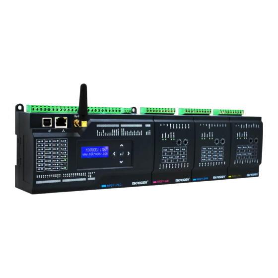
MP211 GENERAL INFORMATION 1.1 Physical Interfaces Figure 1 Connector and Physical Interfaces Digital Input GND Connection USB Port Analog Output Connections Relay Status Information LED Analog GND Connection Digital Output Status Information LED Analog Input Connection Digital Input Status Information LED RS485 Connections System Power LED RS-232 GND Connections... -
Page 8: General Device Specifications
1.2 General Device Specifications SPECIFICATION ITEM DESCRIPTION Processor Architecture ARM Cortex M4 Processor Adressing Architecture Little Endian Addressing Supply 24 VDC (12-36VDC) Electrical Power <13W @ 24V DC Real Time Clock Integrated Digital Input 16 Channel Digital Output 8 Channel, 2A@30V DC, PNP Input / Output Analog Input 4 Channel, 0-20 mA, 4-20 mA... -
Page 9: Installation Information
INSTALLATION INFORMATION 2.1 Rail Installation DIN Rail Mountage First, the upper part of the device is mounted on the DIN rail. Then, with the help of the springs behind the device, when a lightly force is applied to the lower part, the device locates into the DIN rail easily and the montage is completed. -
Page 10: Expansion Installation
2.2 Expansion Installation The MP211 product and its extensions are mounted by sliding over the rail in such a way that the connectors correponds. Figure 3 Expansion Installation MP211 SERIES – HARDWARE MANUAL... -
Page 11: Connection Diagrams
CONNECTION DIAGRAMS 3.1 Supply Connection Supply: 12-36 VDC, Protected Power: <13 W Figure 4 Power Connection Diagram MP211 SERIES – HARDWARE MANUAL... -
Page 12: Digital Inputs
3.2 Digital Inputs Module Input: 16 Channel Voltage Range: 0-36V DC ON Voltage Level: 12-36V DC OFF Voltage Level: 0-10V DC Input Impedance: >2M Isolation: Optical OFF to ON Response: 20 us ON to OFF Response: 90 us Fast Counter Inputs: DI12, DI13, DI14, DI15 Fast Counter Inputs Max. -
Page 13: Digital Outputs
3.3 Digital Outputs Module Output: 8 Channel, Mosfet Output Voltage Range: 12-36V DC Max. Output Current: 2A @ 30V DC Isolation: Optical Pulse Width Modulation Output and Pulse Train Output: DO1, DO2, DO3, DO4 Pulse Train Output Max. Frequency(PTO): 50 kHz Pulse Width Modulation Output Max. -
Page 14: Relay Outputs
3.4 Relay Outputs Module Output: 4 Channel Relay Contact Outputs: NO(Normally Open) Contact Contact Max. Current: 3A@30VDC – 5A@250VAC Isolation Dry Contact Figure 7 Relay Connection Diagram MP211 SERIES – HARDWARE MANUAL... -
Page 15: Analog Inputs
3.5 Analog Inputs Module Input: 4 Channel Analog Input Type: 0-20 mA, 4-20 mA Analog Input Resolution: 12 Bit Analog Input Precision: %1 Precision Common Input GND: 1 GND (4 Point / Common) Figure 8 Analog Input Connection Diagram MP211 SERIES – HARDWARE MANUAL... -
Page 16: Analog Outputs
3.6 Analog Outputs Module Output: 2 Channel Analog Output Type: 0-20 mA, 4-20 mA Analog Output Resolution: 12 Bit Current Output Precision: %1 Precision Common Output GND: 1 GND (2 Point / Common) Figure 9 Analog Output Connection Diagram MP211 SERIES – HARDWARE MANUAL... -
Page 17: Rs485 Serial Port
3.7 RS485 Serial Port RS485 Port Count: 1 Port, 3 kV ESD Protection Maximum Slave Count Limited to Hardware Isolation: Galvanic and Optical Communication Distance: 1000 m Data Bits: Stop Bits: Parity: None-Even-Odd Baudrate: 300 bps to 200 kbps Figure 10 RS485 Serial Port Connection Diagram MP211 SERIES –... -
Page 18: Rs232 Serial Port
3.8 RS232 Serial Port RS232 Port Count: 1 Port Communication Distance: 10 m Data Bits: Stop Bits: Parity: None-Even-Odd Baudrate: 300 bps to 200 kbps Figure 11 RS232 Serial Port Connection Diagram MP211 SERIES – HARDWARE MANUAL...
Need help?
Do you have a question about the PLC Series and is the answer not in the manual?
Questions and answers