
Related Manuals for Xtreme Power Conversion XPRT 6/10KVA


Summary of Contents for Xtreme Power Conversion XPRT 6/10KVA
- Page 1 UNINTERRUPTIBLE POWER SUPPLY (UPS) XPRT 6/10KVA Online UPS Dual-Inverter Rack Tower Models USER & INSTALLATION MANUAL www.xpcc.com | © 2013 Xtreme Power Conversion Corporation. All rights reserved.
-
Page 2: Table Of Contents
Connecting Internal Battery Pack (10kVA Model) .................. 26 Connecting Additional External Battery Packs (6kVA Model) ..............28 Connecting Additional External Battery Packs (10kVA Model) .............. 31 Connecting Interface Devices ......................... 34 Standard Hardwired Installation Procedure ................... 36 Xtreme Power Conversion® (XPC) Corporation (Rev 2/7/13) Page 2... - Page 3 Bypass Out of Limits ..........................57 Overload ..............................57 Replace Battery ............................57 Alarm Priority ............................58 Fault Mode .............................. 58 Standby ..............................59 Remote Emergency Power Off (REPO) ....................59 No Load Shutdown ..........................60 Xtreme Power Conversion® (XPC) Corporation (Rev 2/7/13) Page 3...
- Page 4 LOAD PROTECTION POLICY ....ERROR! BOOKMARK NOT XTREME POWER CONVERSION (XPC) CORPORATION LIMITED WARRANTY ......75 ® DEFINED. XTREME POWER CONVERSION ® APPENDIX A – SNMP/WEB CARD (OPTIONAL) ..................78 Introduction ............................78 Xtreme Power Conversion® (XPC) Corporation (Rev 2/7/13) Page 4...
-
Page 5: Introduction
Modifications not expressly approved by the manufacturer could void the user’s authority to operate the equipment under FCC rules. Xtreme Power Conversion® (XPC) Corporation (Rev 2/7/13) Page 5... -
Page 6: Important Safety Instructions
UPS system. Xtreme Power Conversion (XPC) Corp refuses any responsibility in case of non-observance, unauthorized alterations, or improper use of the delivered UPS. - Page 7 Do not stack other package on top. WARNING! Pay attention to the HEAVY WEIGHT of the UPS when downloading the UPS from the pallet! Never try to lift the unit by yourself! Xtreme Power Conversion® (XPC) Corporation (Rev 2/7/13) Page 7...
-
Page 8: General
If the unit is stored for an extended period of time, the batteries must be recharged periodically. Connect the unit to a wall outlet and recharge the batteries for 24 hours: Xtreme Power Conversion® (XPC) Corporation (Rev 2/7/13) Page 8... -
Page 9: Maintenance And Servicing
Contact with any part of a grounded battery can result in electrical shock. The likelihood of such shock will be reduced if such grounds are removed during installation and maintenance. • Avoid charging in a sealed container Xtreme Power Conversion® (XPC) Corporation (Rev 2/7/13) Page 9... -
Page 10: Introduction
To prevent power line problems from reaching critical systems causing damage to software, hardware, and equipment malfunctions, the UPS maintains constant voltage, isolating critical load output and cleaning the utility AC power. Xtreme Power Conversion® (XPC) Corporation (Rev 2/7/13) Page 10... -
Page 11: Double Conversion On-Line Technology
DC power is converted to AC in the inverter, passing it on to the load. • Power is maintained from the battery during a power failure. • The converter increases voltage appropriately for the inverter. FIG. 1 - BLOCK DIAGRAM Xtreme Power Conversion® (XPC) Corporation (Rev 2/7/13) Page 11... -
Page 12: Efficiency Optimizer Function
Backup time required will indicate the battery size needed. If the load is less than the UPS nominal power rating, then actual backup time is longer. • The following options are available: o Extended Battery Packs (maximum of 3 battery packs of same model) Xtreme Power Conversion® (XPC) Corporation (Rev 2/7/13) Page 12... - Page 13 XPD1420HV-90000045 provides 12FT 5-20P INPUT + (14)5-20R XPD1420HVA-90000050 provides 12FT 5-20P INPUT + (14)5-20R + AMP METER See the Specification section of this manual for addition model information. FIG 2 – 6kVA FRONT VIEW Xtreme Power Conversion® (XPC) Corporation (Rev 2/7/13) Page 13...
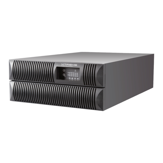
- Page 14 XPRT-6kVA, XPRT-10kVA USER’S MANUAL UNINTERRUPTIBLE POWER SUPPLY (UPS) FIG 3 – 10kVA FRONT VIEW Xtreme Power Conversion® (XPC) Corporation (Rev 2/7/13) Page 14...
- Page 15 FIG 4 – XPRT-6000HB-90000036 BUNDLE REAR VIEW (WITH UPS, INTERNAL BATTERY & HARDWIRE PDU) FIG 4 – XPRT-6000B-90000013 BUNDLE REAR VIEW (WITH UPS, INTERNAL BATTERY & RECEPTACLE PDU (4) 5-20R + (1) L6-30R + (1) L14-30R) Xtreme Power Conversion® (XPC) Corporation (Rev 2/7/13) Page 15...
- Page 16 XPRT-6kVA, XPRT-10kVA USER’S MANUAL UNINTERRUPTIBLE POWER SUPPLY (UPS) FIG 4 – XPRT-10000B-90000014 REAR VIEW (STANDARD HARDWIRE + INTERNAL BATTERIES) FIG 4 – XPRT-10000-90000016 + XPRT-PDU3-90000035 REAR VIEW Xtreme Power Conversion® (XPC) Corporation (Rev 2/7/13) Page 16...
- Page 17 XPRT-6kVA, XPRT-10kVA USER’S MANUAL UNINTERRUPTIBLE POWER SUPPLY (UPS) (W/ PDU (4) 5-20R + (2) L5-20R + (2) L6-30R) FIG 5 – FRONT PANEL – HORIZONTAL FIG 6 – FRONT PANEL – VERTICAL Xtreme Power Conversion® (XPC) Corporation (Rev 2/7/13) Page 17...
- Page 18 When the Alarm LED is on, this bar may show a combination of LEDs, describing the Alarm cause. 1 LED = 0-20% 2 LEDs = 21-40% 3 LEDs = 41-60% Xtreme Power Conversion® (XPC) Corporation (Rev 2/7/13) Page 18...
-
Page 19: Hardware Installation Guide
1 internal battery pack, and for the 10kVA model there are 2 internal battery packs are shipped separately. WARNING! In case of recognizable damage: DO NOT connect any voltage to the unit DO NOT put the unit into operation Xtreme Power Conversion® (XPC) Corporation (Rev 2/7/13) Page 19... -
Page 20: Safety Information
The total power demand of the connected equipment does not exceed the rated output power of the XPRT Series UPS CAUTION To reduce risk of fire, connect the UPS only to a circuit provided with fuse or circuit breaker values as shown above. Xtreme Power Conversion® (XPC) Corporation (Rev 2/7/13) Page 20... -
Page 21: Installation Procedures
2. Assemble the plastic support feet and mount them to UPS bottom (see FIG 7 or FIG 8) 3. Place the cabinet upright and mount top covers 4. Attach the display sticker FIG 7 – XPRT-6KVA TOWER ASSEMBLY Xtreme Power Conversion® (XPC) Corporation (Rev 2/7/13) Page 21... -
Page 22: Rack Mount Installation
2. Install the mounting brackets that came with the unit using the provided screws (see FIG 9 or 10) 3. Install the UPS into a 19’ rack. The UPS cabinet must be supported by mounting rails, do not mount it by using the mounting brackets only. Xtreme Power Conversion® (XPC) Corporation (Rev 2/7/13) Page 22... - Page 23 Fit the unit and the battery into the rack cabinet with the help of a second person. FIG 11 – XPRT 6-10KVA RACK MOUNT ASSEMBLY Xtreme Power Conversion® (XPC) Corporation (Rev 2/7/13) Page 23...
-
Page 24: Connecting Internal Battery Pack (6Kva Model)
4. Fix the battery cover by tightening screws (see FIG 14). 5. Mount the front panels by pushing the plastic part into the appropriate holes (see FIG 15). 6. Proceed with the UPS installation. Xtreme Power Conversion® (XPC) Corporation (Rev 2/7/13) Page 24... - Page 25 XPRT-6kVA, XPRT-10kVA USER’S MANUAL UNINTERRUPTIBLE POWER SUPPLY (UPS) FIG 13 – XPRT-6KVA SLIDE BATTERY PACK INTO UPS FIG 14 – XPRT-6KVA ATTACH BATTERY COVER ON UPS Xtreme Power Conversion® (XPC) Corporation (Rev 2/7/13) Page 25...
-
Page 26: Connecting Internal Battery Pack (10Kva Model)
4. Fix the battery cover by tightening screws (see FIG 17). 5. Mount the front panels by pushing the plastic part into the appropriate holes (see FIG 18). 6. Proceed with the UPS installation. Xtreme Power Conversion® (XPC) Corporation (Rev 2/7/13) Page 26... - Page 27 XPRT-6kVA, XPRT-10kVA USER’S MANUAL UNINTERRUPTIBLE POWER SUPPLY (UPS) FIG 16 – XPRT-10KVA SLIDE BATTERY PACKs INTO UPS FIG 17 – XPRT-10KVA ATTACH BATTERY COVER ON UPS Xtreme Power Conversion® (XPC) Corporation (Rev 2/7/13) Page 27...
-
Page 28: Connecting Additional External Battery Packs (6Kva Model)
(see FIG 20). On first startup the value of the total battery capacity has to be set with the UPS Monitoring software. Xtreme Power Conversion® (XPC) Corporation (Rev 2/7/13) Page 28... - Page 29 XPRT-6kVA, XPRT-10kVA USER’S MANUAL UNINTERRUPTIBLE POWER SUPPLY (UPS) FIG 19 – XPRT-6KVA UPS + BATTERY PACK FIG 20 – XPRT-6KVA UPS + BATTERY PACK CABLE CONNECTION Xtreme Power Conversion® (XPC) Corporation (Rev 2/7/13) Page 29...
- Page 30 UPS, the batteries start charging. For best results, allow the UPS to recharge the batteries during a period of approx. 8 hours. It is acceptable to use the UPS without first charging the battery, but the runtime may be reduced. Xtreme Power Conversion® (XPC) Corporation (Rev 2/7/13) Page 30...
-
Page 31: Connecting Additional External Battery Packs (10Kva Model)
Install the battery grille in front of the battery compartment with 3 screws (see FIG 23) Mount the 2 battery pack front covers (see FIG 23) FIG 22 – XPRT-10KVA BP5 BATTERY TRAY INSTALLATION Xtreme Power Conversion® (XPC) Corporation (Rev 2/7/13) Page 31... - Page 32 Connect the cable provided with the battery between UPS and battery pack – plug it into the UPS battery socket and the nearest battery connection socket on the battery pack (FIG 25). Xtreme Power Conversion® (XPC) Corporation (Rev 2/7/13) Page 32...
- Page 33 If further battery packs are used, they connect via the previous battery pack. Thus, the cable provided is attached via the nearest socket connection on the existing battery cabinet (FIG 26). Xtreme Power Conversion® (XPC) Corporation (Rev 2/7/13) Page 33...
-
Page 34: Connecting Interface Devices
You can now connect the DB9 port to a computer system by connecting the previously prepared serial cable (FIG 28). Additional signals can be read from the serial connector, refer to following table for details. Xtreme Power Conversion® (XPC) Corporation (Rev 2/7/13) Page 34... - Page 35 Open the SNMP slot by removing the two screws and the cover, then pull in the easy installation SNMP Card and connect previously prepared network cable (FIG 29 or FIG 30). Xtreme Power Conversion® (XPC) Corporation (Rev 2/7/13) Page 35...
-
Page 36: Standard Hardwired Installation Procedure
1. For installation with Optional Power Distribution Unit please see the appropriate section of this manual. 2. Remove the terminal cover (see FIG 30 or 31) Xtreme Power Conversion® (XPC) Corporation (Rev 2/7/13) Page 36... - Page 37 FIG 31 – HARDWIRE INSTALL 10KVA UPS 3. Punch out the appropriate holes in the terminal cover. Secure the input/output cables using appropriate hardware as shown in FIG 32. FIG 32 – HARDWIRE INSTALL 6/10KVA UPS Xtreme Power Conversion® (XPC) Corporation (Rev 2/7/13) Page 37...
- Page 38 FIG 34 – HARDWIRE WIRE CONNECTIONS 10KVA UPS 5. Output: connect the load wires to the terminals L1-L2 (Line) and N (Neutral) and the ground wire to GRD. Ground connection is essential! (see FIG 33 or FIG 34). Xtreme Power Conversion® (XPC) Corporation (Rev 2/7/13) Page 38...
- Page 39 For 6kVA models an additional ground connection is required (the main ground can be removed with the PDU). Connect the UPS case to the nearest available ground connection with an 8 AWG (10 mm copper wire (see FIG 37). Xtreme Power Conversion® (XPC) Corporation (Rev 2/7/13) Page 39...
-
Page 40: Optional Power Distribution Units
4. On the 6kVA model, loosen the three mounting screws (FIG 38) on the installed PDU until the PDU can be removed from the UPS cabinet. FIG 38 – PDU REMOVAL 6KVA UPS Xtreme Power Conversion® (XPC) Corporation (Rev 2/7/13) Page 40... - Page 41 8. On the 10kVA model, connect terminals on the backside of the PDU with connections in the PDU tray on the backside of the UPS, and slide the PDU into the UPS (FIG 41). Xtreme Power Conversion® (XPC) Corporation (Rev 2/7/13) Page 41...
-
Page 42: Startup
FIG 42 – 6KVA BATTERY PACK BREAKER 3. Ensure that the manual bypass switch on the PDU is turned to the “UPS” position (FIG 43). FIG 43 – 6KVA PDU BYPASS SWITCH Xtreme Power Conversion® (XPC) Corporation (Rev 2/7/13) Page 42... -
Page 43: Startup 10Kva Ups (Stand-Alone Not Parallel Systems)
FIG 46 – 10KVA BATTERY PACK BREAKER 3. Ensure that the bypass circuit breaker on the UPS is turned to the “UPS” position (FIG 47), or that the protection bar is still mounted. Xtreme Power Conversion® (XPC) Corporation (Rev 2/7/13) Page 43... - Page 44 FIG 49 – 10KVA OUTPUT CIRCUIT BREAKER 9. The UPS is now in operation; equipment connected to the UPS output can now be switched on. 10. Load % will be shown on the “LOAD” LED BAR. Xtreme Power Conversion® (XPC) Corporation (Rev 2/7/13) Page 44...
-
Page 45: Operation
If electrical isolation is required (e.g. for maintenance purposes) proceed with the following steps 4. Turn the OUPUT CIRCUIT BREAKER to OFF position (FIG 51 or FIG 52). FIG 51 – 6KVA OUTPUT BREAKER Xtreme Power Conversion® (XPC) Corporation (Rev 2/7/13) Page 45... - Page 46 7. Open all switches and breakers upstream to the UPS. 8. Remove internal and external battery pack connections and disconnect additional battery packs. All LEDs should be out on the front panel of the UPS; the UPS is shutdown. Xtreme Power Conversion® (XPC) Corporation (Rev 2/7/13) Page 46...
-
Page 47: Maintenance Bypass
2. The UPS is now operating in UTILITY BYPASS MODE and maintenance can be performed. NOTE After the UPS is shutdown or in “External Bypass” condition, the residual DC voltage in the unit will be eliminated within 5 minutes. Xtreme Power Conversion® (XPC) Corporation (Rev 2/7/13) Page 47... -
Page 48: 10Kva Parallel Installation And Operation
Now the UPS is protecting the load again. 10KVA PARALLEL INSTALLATION AND OPERATION The paralleling cable delivered with each 10kVA UPS allows you to connect up to (3) 10kVA UPS together in a parallel system. Xtreme Power Conversion® (XPC) Corporation (Rev 2/7/13) Page 48... -
Page 49: Installation Of A Parallel System
Optional Xtreme Power paralleling / bypass panels are available to accomplish this (not shown). Please contact Xtreme Power Sales for additional information. FIG 59 – 10KVA UPS PARALLEL SYSTEM DIAGRAM EXAMPLE Xtreme Power Conversion® (XPC) Corporation (Rev 2/7/13) Page 49... - Page 50 The overall system load may not exceed 100% load of a single UPS in the configuration without the addition of an external maintenance bypass. Optional Xtreme Power bypass panel is available to meet this requirement. Please contact Xtreme Power Sales for additional information. Xtreme Power Conversion® (XPC) Corporation (Rev 2/7/13) Page 50...
-
Page 51: Installing The Parallel Connection
3. One cable connects two UPS is parallel. To connect a third UPS into the parallel system, repeat the process as above (FIG 62). FIG 62 – 10KVA UPS CONNECTING 3 PARALLEL UNITS Xtreme Power Conversion® (XPC) Corporation (Rev 2/7/13) Page 51... -
Page 52: Startup 10Kva Ups Parallel System
1. The UTILITY INPUT is present and within the tolerance as show in Specification section of this manual. 2. The UPS is turned ON. 3. The LOAD does not exceed the capacity of the UPS. 4. The OPERATING TEMPERATURE is below alarm level. Xtreme Power Conversion® (XPC) Corporation (Rev 2/7/13) Page 52... -
Page 53: Switching The Ups Off
If electrical isolation is required (e.g. for maintenance purposes) proceed with the following steps FIG 65 – 10KVA OUTPUT BREAKER 5. Turn the INPUT CIRCUIT BREAKER to OFF position (FIG 66). FIG 66 – 10KVA INPUT BREAKER Xtreme Power Conversion® (XPC) Corporation (Rev 2/7/13) Page 53... - Page 54 8. Remove internal and external battery pack connections and disconnect additional battery packs. All LEDs should be out on the front panel of the UPS; the UPS is shutdown. REPEAT STEP FOR ADDITIONAL 10KVA UPS IN PARALLEL CONFIGURATION Xtreme Power Conversion® (XPC) Corporation (Rev 2/7/13) Page 54...
-
Page 55: Status And Alarm Indications
− − − = INTERMITTENT ––– = CONTINUOUS 0-5 = NUMBER OF LEDs THAT CAN BE ON DEPENDING ON RUNTIME CAPACITY / LOAD BAR MUTE BUZZER = PRESS BUTTON “|” BRIEFLY Xtreme Power Conversion® (XPC) Corporation (Rev 2/7/13) Page 55... -
Page 56: On Bypass
When the batteries are fully discharged, the UPS is no longer able to supply the connected equipment and eventually output power is lost. Xtreme Power Conversion® (XPC) Corporation (Rev 2/7/13) Page 56... -
Page 57: Bypass Out Of Limits
(partially) discharged during transport or storage or during the power failure. For this reason we advise to execute battery test only after 5 hours on line operation with no input utility failures. This allows the UPS to recharge the batteries. Xtreme Power Conversion® (XPC) Corporation (Rev 2/7/13) Page 57... -
Page 58: Alarm Priority
− − − ––– ––– TEMPERATURE 1/4 SEC − − − BEZEL INTERLOCK ––– ––– ––– ––– 1/4 SEC LEGEND H = HIGH PRIORITY ALARMS − − − = INTERMITTENT ––– = CONTINUOUS Xtreme Power Conversion® (XPC) Corporation (Rev 2/7/13) Page 58... -
Page 59: Standby
When REPO is activated the UPS will transfer to stand-by mode and output power is lost. It’s not possible to restart the unit while the REPO is activated, thus, depending on the used switch, the connection must be Xtreme Power Conversion® (XPC) Corporation (Rev 2/7/13) Page 59... -
Page 60: No Load Shutdown
When executing a deep battery test, the available runtime in case of input utility failure may be shorter than normal. Don’t execute this test if reduced battery runtime is not acceptable. Xtreme Power Conversion® (XPC) Corporation (Rev 2/7/13) Page 60... -
Page 61: Communication
The change of some settings can cause the unit to switch from bypass to standby and output power is lost. For more information regarding possible settings, please refer to the HELP manual on the UPS Monitoring Software CD. Xtreme Power Conversion® (XPC) Corporation (Rev 2/7/13) Page 61... -
Page 62: Snmp Interface Card (Option)
Pack is the normal configuration. ESTIMATED RUNTIME IN MINUTES UNIT LOAD INTERNAL 1 BATTERY 2 BATTERY 3 BATTERY 4 BATTERY BATTERIES PACK PACKS PACKS PACKS XPRT- 6000 100% XPRT- 10000 100% Xtreme Power Conversion® (XPC) Corporation (Rev 2/7/13) Page 62... -
Page 63: Maintenance
Proper disposal or recycling of the batteries is required. Refer to your local codes for disposal requirements. Xtreme Power Conversion Corp, in compliance with environment protection recommends that the UPS equipment, at the end of its service life, must be recycled conforming to the local applicable regulations. -
Page 64: Batteries
1. Remove the UPS front cover from the UPS cabinet by gently pulling it out. 2. Remove the battery grille by loosening the two mounting screws (FIG 69). Xtreme Power Conversion® (XPC) Corporation (Rev 2/7/13) Page 64... - Page 65 6. Slide the battery tray into the battery compartment until the rear connector is plugged with the UPS internal DC socket. 7. Fix the battery grille by tightening screws. 8. Re-install the two front covers. Xtreme Power Conversion® (XPC) Corporation (Rev 2/7/13) Page 65...
-
Page 66: Internal Battery Replacement - 10Kva Model
3. Disconnect DC cabling from battery tray connectors. 4. Grab hold of the battery trays and slide it out. (FIG 72). Be careful during this operation and consider the weight of the battery. Xtreme Power Conversion® (XPC) Corporation (Rev 2/7/13) Page 66... -
Page 67: Power Unit Maintenance
For maintenance purposes, the power unit can be replaced while output is transferred to manual bypass. See the following detailed steps for the replacement procedure. WARNING The UPS has to be switched to manual bypass before power unit replacement, otherwise output power is lost. Xtreme Power Conversion® (XPC) Corporation (Rev 2/7/13) Page 67... -
Page 68: Power Unit Replacement - 6Kva Model
6. Switch the UPS back to normal operation. Power Unit Replacement – 10kVA Model 1. Switch the UPS to manual bypass. 2. Remove the 3 front covers (FIG 75). FIG 75 – 10KVA POWER UNIT REMOVAL Xtreme Power Conversion® (XPC) Corporation (Rev 2/7/13) Page 68... -
Page 69: Troubleshooting
The following chart is a simple troubleshooting checklist. If the suggested solution does not succeed, or if the information is insufficient to solve the problem, please contact your dealer or consult www.xpcc.com. Xtreme Power Conversion® (XPC) Corporation (Rev 2/7/13) Page 69... - Page 70 Check whether correct cable is and load used PC interface defective or being Check if no other software is accessing the interface accessed by another service Interference on the data cable Rearrange cables Xtreme Power Conversion® (XPC) Corporation (Rev 2/7/13) Page 70...
-
Page 71: Specifications
(4) 5-20R + (2) L5-20R + (2) L6-30R Communication RS-232 and USB standard, SNMP (optional card) Interface Battery Pack 16.9” x 22.5” x 3.5” (2U) 16.9” x 26.0” x 6.8” (4U) Dimensions Xtreme Power Conversion® (XPC) Corporation (Rev 2/7/13) Page 71... - Page 72 0 - 40ºC (32 - 104ºF) Audible Noise < 55dba Altitude 11500 ft (3500 m) above sea level WARRANTY Warranty Three years electronics / Three years batteries APPROVALS North America UL cUL FCC Xtreme Power Conversion® (XPC) Corporation (Rev 2/7/13) Page 72...
-
Page 73: Shipping List
2. (1) User’s and Installation Manual 3. (1) 6 ft USB-DB9 adaptor cable 4. (1) UPS Monitoring Software CD 5. (2) sets of tower brackets 6. (2) sets of horizontal mounting brackets Xtreme Power Conversion® (XPC) Corporation (Rev 2/7/13) Page 73... -
Page 74: Obtaining Service
3. Call your dealer for assistance. If you cannot reach your dealer, or if they cannot resolve the problem, call Xtreme Power Conversion Corp Technical Support at 800.582.4524 or 720.292.1217. Technical support inquires can also be made at support@xpcc.com. Please have the following information available BEFORE calling the Technical Support Department: a. -
Page 75: (Xpc) Corporation Limited Warranty
XPC Corporation or a XPC Corporation authorized representative before or after delivery with regard to the use or application of Xtreme Power Conversion equipment is furnished on the basis that it represents XPC Corporations best judgment under the situation and circumstances, but it is used at the recipient’s sole risk. - Page 76 Product in its original condition which was properly operated when a Power Disturbance passed through the Product and (i) exhausts the protection capacity of the Product or (ii) damages the Product. Xtreme Power Conversion® (XPC) Corporation (Rev 2/7/13) Page 76...
- Page 77 Connected Equipment. XPC reserves the right to contact the authorized service center directly to discuss repair costs and damage to the Connected Equipment to determine if it was Xtreme Power Conversion® (XPC) Corporation (Rev 2/7/13) Page 77...
-
Page 78: Appendix A - Snmp/Web Card (Optional)
This addendum to the XPRT 6 / 10 kVA User’s Manual provides information on the optional SNMP/Web Card that can be used with these products. FIG 77 – SNMP/WEB CARD FRONT VIEW Xtreme Power Conversion® (XPC) Corporation (Rev 2/7/13) Page 78... -
Page 79: Leds
UPS status / alarms / readings; event logging over different interfaces • Digital outputs (open-collector outputs for relay drive) • SNMP Traps and E-mail notification upon UPS event • Advanced security features Xtreme Power Conversion® (XPC) Corporation (Rev 2/7/13) Page 79... -
Page 80: Architecture
XPRT-6kVA, XPRT-10kVA USER’S MANUAL UNINTERRUPTIBLE POWER SUPPLY (UPS) Architecture FIG 78 – COMMUNICATIONS ARCHITECTURE Xtreme Power Conversion® (XPC) Corporation (Rev 2/7/13) Page 80... -
Page 81: Installation
If switching to maintenance bypass, make sure the utility input voltage is stable before switching. • Install the SNMP/Web Card in the option slot on the rear of the UPS. FIG 79 – SNMP INSTALL 6kVA UPS FIG 80 – SNMP INSTALL 10kVA UPS Xtreme Power Conversion® (XPC) Corporation (Rev 2/7/13) Page 81... -
Page 82: Interfaces
Note: Although the console interface provides a full set of commands, access using the serial connection is only needed for initial configuration when no DHCP server is available, or the IP-address is unknown. Xtreme Power Conversion® (XPC) Corporation (Rev 2/7/13) Page 82... - Page 83 The SNMP/Web Card connects to the network using the following parameters: IP ADDRESS IDENTIFIES THE CARD ON THE NETWORK SUBNET MASK DEFINES A RANGE OF ADDRESSES WITHIN THE ORANIZATION GATEWAY THE NODE USED FOR CONNECTION TO ADDRESSES OUSIDE THE SUBNET Xtreme Power Conversion® (XPC) Corporation (Rev 2/7/13) Page 83...
- Page 84 XPRT-6kVA, XPRT-10kVA USER’S MANUAL UNINTERRUPTIBLE POWER SUPPLY (UPS) The card can be configured to obtain these settings automatically using DHCP or BOOTP protocols, or to use static addresses (manual configuration). Xtreme Power Conversion® (XPC) Corporation (Rev 2/7/13) Page 84...
-
Page 85: Access
Check the Ethernet connection to the card by launching a ping command from a workstation in the same subnet. • Select Run from the Start menu • Enter ping <IP> (e.g. ping 192.168.24.14) • Verify that the SNMP Card is correctly replying Xtreme Power Conversion® (XPC) Corporation (Rev 2/7/13) Page 85...
Need help?
Do you have a question about the XPRT 6/10KVA and is the answer not in the manual?
Questions and answers