Table of Contents
Advertisement
Quick Links
USE AND CARE GUIDE
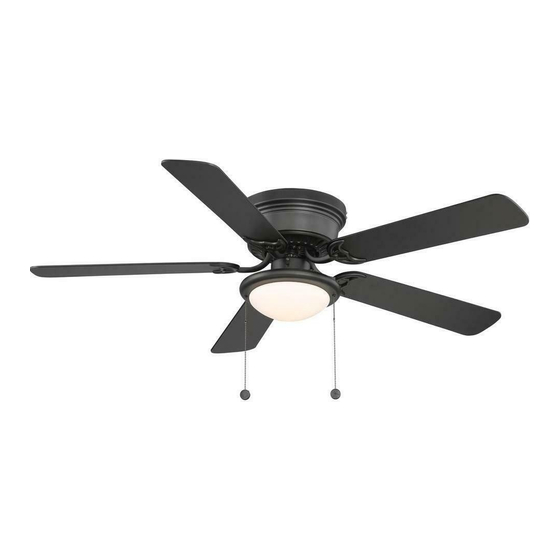
HUGGER LED 52 IN. CEILING FAN
Questions, problems, missing parts? Before returning to the store call
Home Depot Customer Service
8 a.m. - 7 p.m., EST, Monday-Friday, 9 a.m. - 6 p.m., EST Saturday
1-877-527-0313
HOMEDEPOT.COM
THANK YOU
THANK YOU
Item #1002 493 483
#1003 023 395
#1003 023 403
Model # AL383LED-BK
# AL383LED-EB
# AL383LED-GM
Advertisement
Table of Contents

Subscribe to Our Youtube Channel
Related Manuals for Home Depot AL383LED-BK


Summary of Contents for Home Depot AL383LED-BK
- Page 1 Item #1002 493 483 #1003 023 395 #1003 023 403 Model # AL383LED-BK # AL383LED-EB # AL383LED-GM USE AND CARE GUIDE HUGGER LED 52 IN. CEILING FAN Questions, problems, missing parts? Before returning to the store call Home Depot Customer Service 8 a.m.
-
Page 2: Table Of Contents
Table of Contents Table of Contents ............Operation ..............Pull Chain Operating Instructions ........... Safety Information ............Reverse Switch Operating Instructions ........Warranty ................. Care and Cleaning ............Pre-installation .............. Troubleshooting ............Specifications ................Tools Required ................. Service Parts ..............Hardware Included .............. -
Page 3: Safety Information
Safety Information To reduce the risk of electric shock, ensure electricity has However, there is no guarantee that interference will not occur been turned off at the circuit breaker or fuse box before in a particular installation. If this equipment does cause harmful beginning. -
Page 4: Warranty
Warranty We warrant the fan motor to be free from defects in workmanship and material present at time of shipment from the factory for a period of 15 years after the date of purchase by the original purchaser. We agree to correct such defects without charge or at our option replace with a comparable or superior model if the product is returned. -
Page 5: Hardware Included
Pre-Installation (continued) HARDWARE INCLUDED HARDWARE INCLUDED NOTE: Hardware not shown to actual size. Part Part Description Description Quantity Quantity Blade attachment screw and fiber washer Plastic wire nut Mounting plate screw and lock washer Motor housing screw and lock washer (preassembled) Blade arm screw and lock washer (preassembled) Light kit mounting screw (preassembled) Light holder thumbscrew (preassembled) -
Page 6: Package Contents
Pre-Installation (continued) PACKAGE CONTENTS PACKAGE CONTENTS Part Part Description Description Quantity Quantity Part Part Description Description Quantity Quantity Mounting plate Blade arm Fan motor assembly Light kit Motor housing Glass shade Blade... -
Page 7: Installation
Installation MOUNTING OPTIONS MOUNTING OPTIONS WARNING: To reduce the risk of fire, electric shock, or personal injury, mount the fan to an outlet box marked acceptable for fan support using the screws provided with the outlet box. An outlet box commonly used for the support of lighting fixtures may not be acceptable for fan support and may need to be replaced. -
Page 8: Assembly
Assembly — Hanging the Fan Hanging the fan from the Attaching the mounting plate mounting plate to the electrical box □ Carefully lift the fan motor assembly (B) and insert WARNING: To reduce the risk of fire, electric shock or the T section of the mounting bar (MM) into the slot other personal injury, mount the fan only to an outlet box or in the mounting plate (A). - Page 9 Assembly — Hanging the Fan (continued) Making the electrical connections Ground WARNING: To avoid possible electrical shock, be sure conductor Neutral electricity is turned off at the main fuse box before wiring. Black White WARNING: Check to see that all connections are tight, including ground, and that no bare wire is visible at the wire nuts (except for the ground wire).
- Page 10 Assembly — Hanging the Fan (optional) Single Switch Connections Dual Switch Connections □ □ On a single switch the fan and light can be turned on or On a dual switch the fan and light can be turned on or off off together.
- Page 11 Assembly — Hanging the Fan (continued) Attaching the motor housing Finishing the fan installation to the mounting plate □ □ Swing the motor assembly (B) up into position under Carefully lift the motor housing (C) onto the mounting the mounting plate (A). Secure the mounting bar (MM) plate (A), properly align the holes and tighten the to the mounting plate (A) with the screws and lock motor housing (C) with the four screws and lock...
-
Page 12: Attaching The Fan Blades
Assembly — Attaching the Fan Blades Attaching the blades to Fastening the blade the blade arms assemblies to the motor □ Attach the blades (D) to the blade arms (E) using the WARNING: To reduce the risk of personal injury, do not three blade attachment screws and fiber washers bend the blade arms (E) while installing, balancing the blades (AA). -
Page 13: Installing The Light Kit
Assembly — Installing the Light Kit Attaching the light kit to Installing the light bulb the switch housing and glass shade □ Install 1 x 9W Medium base LED bulb (HH) (included). CAUTION: Before starting installation, disconnect the power by turning off the circuit breaker or removing the fuse □... - Page 14 Assembly — Installing the Light Kit (continued) Installing the fan without the light kit (optional) □ Disassemble the switch housing cover (NN) from the light kit (F). You can keep the light kit (F) for future use. □ Attach the plastic plug (II) to the switch housing cover (NN).
-
Page 15: Operation
Operation PULL CHAIN OPERATING INSTRUCTIONS PULL CHAIN OPERATING INSTRUCTIONS Attach the two pull chains and fobs (JJ) to the pull chains located on the switch housing (OO). Turn on the power and check the operation of the fan. The pull chain controls the fan speed as follows: 1 pull - High, 2 pulls - Medium, 3 pulls - Low and 4 pulls - Off. -
Page 16: Care And Cleaning
Care and Cleaning Do Do Do not Do not □ □ Check the support connections, brackets, and blade Use water when cleaning. Water could damage the motor, attachments twice a year. Make sure they are secure. or the wood, or possibly cause an electrical shock. Because of the fan’s natural movement, some □... - Page 17 Troubleshooting (continued) Problem Problem Solution Solution □ Verify that all blades and blade bracket screws are secure (most fan wobble problems are caused by loose parts). Once the fan is properly installed, run the ceiling fan for 10 minutes to let the fan self-adjust.
-
Page 18: Service Parts
Service Parts Part Part Description Description Part Part Description Description Mounting plate Blade attachment screw and fiber washer Fan motor assembly Plastic wire nut Motor housing Mounting plate screw and lock washer Blade Motor housing screw and lock washer (preassembled) Blade arm Blade arm screw and lock washer (preassembled) Light kit... - Page 19 Questions, problems, missing parts? Before returning to the store call Home Depot Customer Service 8 a.m. - 7 p.m., EST, Monday-Friday, 9 a.m. - 6 p.m., EST Saturday 1-877-527-0313 HOMEDEPOT.COM Retain this manual for future use.
Need help?
Do you have a question about the AL383LED-BK and is the answer not in the manual?
Questions and answers