Table of Contents
Advertisement
Quick Links
Advertisement
Table of Contents

Related Manuals for Omega PHCN-962


Summary of Contents for Omega PHCN-962
- Page 3 Preface This manual serves to explain the use of PHCN-962 series controller / transmitter. This instruction manual is written to cover as many anticipated applications of PHCN-962 series controller / transmitter. The information presented in this manual is subject to change without notice as improvements are...
- Page 4 SAFETY INFORMATION OMEGA ENGINEERING. Controller / Transmitter shall be installed and operated only in the manner specified in the Instruction manual. Only skilled, trained or authorized person should carry out installation, setup and operation of the instrument. Before powering up the unit, make sure that power source is connected to, is as specified in the top label.
-
Page 5: Table Of Contents
2.3.3 LED INDUCTION 2.3.4 PASSWORD 2.3.5 PREVIEW OF FUNCTION 3 INSTALLATION AND ACCESSORY INSTALLATION PHCN-962 CONNECTION DIAGRAM MEASUREMENT MODE 4 CALIBRATION MODE ENTERING CALIBRATION MODE pH CALIBRATION ORP–mV CALIBRATION 5 SET UP MODE ENTERING SET UP MODE P01:TEMPERATURE SET-UP SUB-FUNCTION P02:OFFSET SET-UP SUB-FUNCTION... - Page 6 P09:TRANSMITTING RATE SUB FUNCTION 5.10 P10:REVERTING TO FACTORY DEFAULT SETTINGS 5.11 COMMUNICATION PROTOCOL 6 TECHNICAL PARAMETERS TECHNICAL PARAMETERS FORM PARAMETER SETTING AND FACTORY PRELIMINARY VALUE APPENCLIX 2 – pH TEMPERATURE CORRESPONDING TO pH BUFFER SOLUTION APPENCLIX 3 – HYSTERESIS BAND APPENCLIX 4 –...
-
Page 7: Preface
OMEGA ENGINEERING Thank you for using . PHCN-962 series controllers and transmitters. Although this series of pH/OPR controllers / transmitters use advanced technology and meet the requirements of current safety rules, improper use can also threaten the safety of users, and / or cause harmful influences to factory and other equipments. -
Page 8: Safety Instruction
SAFETY INSTRUCTION pH / ORP transmitters should be installed and operated by qualified person who are familiar with the work. Transmitters with problems should not be installed and used. pH / ORP transmitters should be used under the required working condition. pH / ORP transmitters should be open and repaired by clients them selves. -
Page 9: Product Description
2 PRODUCT DESCRIPTION 2.1 DESCRIPTION OF INSTRUMENT SPECIALITY: OMEGA ENGINEERING . pH / ORP transmitters are used to measure pH or ORP and temperature value. pH or ORP measured value can use PLC or LIT to control precisely adding medicine. -
Page 10: Measurement And Control System
Immersion, flow or processing parts with or without grounding electrode. • Terminating controlling parts, eg. Pump or value. • 0/4~20mA can connect with recording instrument. • RS485 can be used as multi-instrument communication. • RL3 relay can be used as many controller and warning. PHCN-962... -
Page 11: Appearance
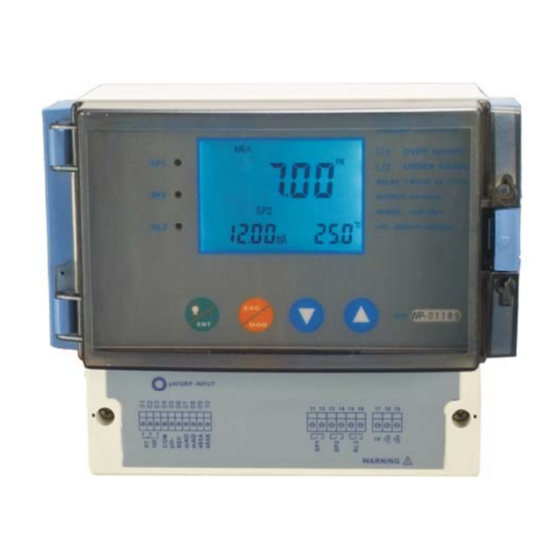
APPEARANCE PHCN-962 Wall hanging installation... -
Page 12: Introduction Of Display
2.3.1 INTRODUCTION OF DISPLAY Two liquid crystal regions show measured value and indication and parameters of various status. CAL SET Mode Indication: 7.00 – MEA: measurement mode – SET : set-up mode – CAL : calibration mode Status Indication: HOLD: relay actions and electric current output are hold. -
Page 13: Key Instruction
2.3.2 KEY INSTRUCTION Description • Mode switch key or quit key • Confirm key • Entering sub-function form of function group in setting mode • Confirm setting parameter and value • Starting calibrating in calibration mode • Back light on and off switch in measurement mode •... -
Page 14: Preview Of Function
2.3.5 PREVIEW OF FUNCTION 7.00 I2.00 25.0 HOLD P02:OFFSET SETUP HOLD HOLD HOLD HOLD P04:CONTROL MODE HOLD HOLD P05:RELAY1 SETUP P06:RELAY2 SETUP HOLD P07:ALARM RELAY HOLD SETUP P08: CONFIG SETUP HOLD HOLD HOLD HOLD P09:RS-485 SETUP HOLD 1 RESET SETUP P 0:... -
Page 15: Installation And Accessory
3 INSTALLATION AND ACCESSORY INSTALLATION Wall-hanging installation (4.449) 113mm 122mm (4.803) 151mm (5.945) -
Page 16: Phcn-962 Connection Diagram
PHCN-962 Warning:Make sure to power off before connecting. The back panel consists of three connectors. PHCN-962 series connection diagram p H/OR P INP UT 11 12 13 14 15 16 17 18 19 S /N: WARNING 1.Temperature electrode positive 17. -
Page 17: Measurement Mode
MEASUREMENT MODE When the controller is initially powered on, it automatically enters into the Measurement mode after the large dual LCD displays all segments briefly. Please notice: in order to get exact measurement information, users should calibrate measurement system (transmitter and electrode). ME A MEA at the top of the LCD shows that the instrument is under the 7.00... -
Page 18: Calibration Mode
4 CALIBRATION MODE You can press once under measurement mode and then input password 28 to get access to calibration mode. Please operate according to following squares. ENTERING CALIBRATION MODE SE T S ET 7.00 HOLD HOLD E NT MO D S P I S P2 I2.00 25.0... -
Page 19: Ph Calibration
pH CALIBRATION This instrument can conduct one point or two points calibration in pre-set standard buffer liquid. The value of standard buffer solution is based on 25℃. You should use those standard buffer solution which matches above solution when you calibrate the instrument. Entering calibration mode as Item 4.1 described. - Page 20 Press twice to quit one-point calibration and return to measuring status. Press to continue next point calibration. Take electrode out of the first standard solution, clean it and put it into the second standard solution. If select one point calibration, instrument will show the slope, but zero point adopts new calibration value while the slope remains the value of last calibration.
- Page 21 NOTE: Press key to quit set up mode at any time. Instrument will return to measurement mode automatically. NOTE: Transmitter will show ERR when calibration is error. Under this situation, press to quit and calibrate again from step 1. It will show ERR again under following situations: (1) Use wrong standard solution or standard solution is expired.
-
Page 22: Orp-Mv Calibration
ORP CALIBRATION If transmitter be set up as ORP measurement mode. You can only calibrate one point. S ET SE T HOLD HOLD EN T M OD S P2 S PI 4.00 C AL 086.0 086.0 HOLD HOLD HOLD ES C S PI 0 .086 6.90... -
Page 23: Set Up Mode
5 SET UP MODE ENTERING SET UP MODE In set up mode, transmitter can be set up according to your need. ME A S E T SE T S ET EN T 7.00 S PI S P2 I2. 00 25.0 Press twice in measurement mode. -
Page 24: P01:Temperature Set-Up Sub-Function
P01:TEMPERATURE SET-UP SUB-FUNCTION 7.00 HOLD HOLD HOLD HOLD HOLD done I2.00 25.0 7.00 HOLD HOLD HOLD done I2.00 25.0 Press to enter from P01 screen. LCD main display zone show ON, which means automatic temperature compensation function, is open. User can press to switch to OFF and close automatic temperature compensation function. -
Page 25: P02:Offset Set-Up Sub-Function
P02:OFFSET SET-UP SUB-FUNCTION HOLD HOLD HOLD 7.00 HOLD 07.00 done I2.00 25.0 1.In P02 sub-function form, Press . LCD main display zone shows pH actually measured value in pH measurement mode. The lower display shows POFS. The right lower display show offset. LCD main display zone shows ORP actually measured value in ORP measurement mode. -
Page 26: P03: Output Electric Circuit(Sp1/Sp2) Sub-Function
P03: OUTPUT ELECTRIC CIRCUIT(SP1/SP2) SUB-FUNCTION HOLD 7.00 HOLD HOLD HOLD HOLD done I2.00 25.0 HOLD 7.00 HOLD HOLD HOLD done I2.00 25.0 Press to confirm in P03 sub-function. Entering set up of the sub-function. The lower display shows CTYP. The upper display shows 4 (it means electric circuit output from 4 m A to 20 m A). -
Page 27: P04:Control Mode Sub-Function
P04:CONTROL MODE SUB-FUNCTION 7.00 HOLD HOLD HOLD done I2.00 25.0 7.00 HOLD HOLD done I2.00 25.0 Press in P04 sub-function form to enter into concrete set up procedure. The lower display shows CNTR while the upper display shows LIT. (The control mode of instrument is under limited control mode). -
Page 28: P05:Relay 1 Set-Up Sub-Function
P05:RELAY 1 SET-UP SUB-FUNCTION HOLD 7.00 HOLD HOLD HOLD done I2.00 25.0 7.00 HOLD HOLD HOLD HOLD HOLD HOLD done I2.00 25.0 7.00 HOLD HOLD HOLD HOLD HOLD done I2.00 25.0 7.00 HOLD HOLD HOLD HOLD HOLD HOLD done I2.00 25.0 In P05 sub-function form. -
Page 29: P06:Relay 2 Set-Up Sub-Function
P06:RELAY 2 SET-UP SUB-FUNCTION Working principle of this part is the same as which of P05 relay 1 set-up sub-function. Please operate according to P05. HOLD HOLD I0.00 7.00 HOLD HOLD done I2.00 25.0 HOLD I0.00 HOLD 7.00 HOLD HOLD HOLD done I2.00 25.0... -
Page 30: P07:Alarm Relay 3 Set-Up Sub-Function
P07:ALARM RELAY 3 SET-UP SUB-FUNCTION HOLD HOLD HOLD HOLD 7.00 done I2.00 25.0 HOLD HOLD HOLD HOLD 7.00 done I2.00 25.0 HOLD HOLD HOLD HOLD 7.00 done I2.00 25.0 Select P07 sub function, Press to confirm. Enter into concrete set-up procedure. Select concrete working mode. -
Page 31: P08:Ph/Orp And Sensor Configuration Sub-Function
P08:pH/ORP FUNCTION AND SENSOR CONFIGURATION SUB-FUNCTION HOLD HOLD 7.00 done I2.00 25.0 HOLD SENS HOLD HOLD 7.00 done HOLD I2.00 25.0 HOLD HOLD FUNC 7.00 done HOLD I2.00 25.0 HOLD HOLD SENS HOLD HOLD 7.00 done I2.00 25.0 7.00 HOLD HOLD done FUNC... -
Page 32: P09:Transmitting Rate Sub Function
P09:TRANSMITTING RATE SUB FUNCTION HOLD HOLD HOLD HOLD HOLD 7.00 done I2.00 25.0 1.Press to confirm in P09 and enter in concrete set-up procedures. 2.The lower display shows nb while the upper display shows 001, which indicates that user is setting communication address ID NO. -
Page 33: P10:Reverting To Factory Default Settings
5.10 P10:REVERTING TO FACTORY DEFAULT SETTINGS HOLD HOLD 7.00 HOLD done I2.00 25.0 HOLD HOLD 7.00 done I2.00 25.0 Press in P10 to enter into concrete set-up procedures. The lower display of the instrument shows DEF while the upper display shows NO (YES). User can press to select necessary items. -
Page 34: Communication Protocol
5.11 COMMUNICATION PROTOCOL 1、protocol setting This instrument uses RS-485 communication. It’s can be connected with 1 to 64 instruments in 2 wires at the same time and communicate with PC. The distance of communication is around 1200M. The data form is “N81”(1 start bit, 8 data bits,1 stop bit, NO verify check code) The baud rate is 300 to 38400 bit/s (usually is 9600 bit/s) Users have to set the ID(NB) of the instruments and the baud rate(BT) before connecting to RS-485 Baud... - Page 35 3、The communication instructions 1) RD: read floating data 2) RE: read the appointment data by start address and bytes (the large byte can not over 28 bytes) 3) RR: read all of data (8-word, 12-byte), totally 28 bytes. 4、Introduce the instructions( the ID is 1) 1)...
- Page 36 RE (read the appointment data) The PC send : 40,30,31,52,45,30,30,adrH,adrL,lthH,lthL,CRH,CRL,0D (total 14 bytes) 40 : the start byte 30 31 : the ID of instrument (the hexadecimal: 0~3FH, ASCII:30 30~33 46); 52 45 : the instruction R, E; 30 30 :reserve adrH adrL : the address of the start parameter byte(the hexadecimal: 0 ~1BH;...
- Page 37 The instrument response : 40,30,31,52,52,D1,D2,………,D55,D56,CRH,CRL,0D(64 bytes) 40 : the start byte 30 31:ID 52 52 : the fix data D1~D56:the parameter of sending (8 double byte,12 byte, total 28 bytes) CRCH,CRCL: CRC 0D: the end byte 4、 Notice for programming the communication program If the instrument receives the data with the start byte is 40 and the count of sequence data over 16 bytes and did not find the 0D then the data is invalid.
-
Page 38: Technical Parameters
6 TECHNICAL PARAMETERS TECHNICAL PARAMETERS FORM PHCN-962 Transmitter / Controller pH Range -2.00 to 16.00 pH Analytical degree & precision 0.01 pH and ± 0.01 pH mV Range -1999 to1999 mV Analytical degree & precision 1 mV / ± 1 mV Temperature -9.9 to 130... -
Page 39: Parameter Setting And Factory Preliminary Value
PARAMETER SETTING AND FACTORY PRELIMINARY VALUE Indication Parameter Symbol Contents Remark Valid range Factor Name y value LOCK Password for entering function 0~200 Auto temperature compensation ON/OFF TSET1 tSt1 Temperature set up of manual Only valid for manual -10.0~100.0℃ 25.0 TSET2 tSt2 Calibration temperature set up... -
Page 40: Appenclix 2 - Ph Temperature Corresponding To Ph Buffer Solution
APPENCLIX 2 – pH TEMPERATURE CORRESPONDING TO pH BUFFER SOLUTION Following form shows standard pH value of pH standard buffer solution under different temperature Temperature ( pH 1.00 pH 4.01 pH 6.86 pH 7.00 pH 9.00 pH 9.18 pH 10.01 0.96 4.01 6.98... -
Page 41: Appenclix 3 - Hysteresis Band
Appenclix 3 – hysteresis band Simple Explanation on the Function of Hysteresis Band SP1 Set to LO SP2 Set to HI RELAY ON RELAY OFF 10.0 FORWARD DIRECTION HYSTERESIS BAND REVERSE DIRECTION (DEFAULT = 0.5 pH) The controller relay activates when the set-point is reached. In the reverse direction, it closes. Relay continues to be active till the value reaches the amount set by hysteresis band. -
Page 42: Appenclix 4 - Control Movement
APPENCLIX 4 – CONTROL MOVEMENT General Instructions Concerning Controller Setting MIN Function MAX Function 100 % 50 % + Xw - Xw Prop. Band Prop. Band SP 1 SP 2 Control characteristic of P-Controller as proportional controller MAX Function MIN Function 100 % 50 % + Xw... - Page 43 Relay Pulse Length T Time [s] Control signal and pulse length control Out put of relay controlled by hysteresis band is time. Crile T for open or close is constant. Different value comes from limited value, increase or decrease of open time is in accordance with proportion range. Following applications:...
-
Page 44: Accessory 5 - Abbreviations In Function Form
ACCESSORY 5 – ABBREVIATIONS IN FUNCTION FORM Character Meaning Measurement mode Calibration mode Confirm Zero point offset Set up Automatic temperature cor Set point 1 Set point 2 Low limit High limit CNtr Control Limited point control Pulse length control Relay Output signal CONF...
Need help?
Do you have a question about the PHCN-962 and is the answer not in the manual?
Questions and answers