
Related Manuals for Pentair THS Series


Summary of Contents for Pentair THS Series
- Page 1 THS SERIES FILTER ® DIAPHRAGM VALVE STYLE FACE PIPING INSTALLATION AND USER’S GUIDE IMPORTANT SAFETY INSTRUCTIONS READ AND FOLLOW ALL INSTRUCTIONS SAVE THESE INSTRUCTIONS...
-
Page 2: Table Of Contents
TABLE OF CONTENTS 1 Principals of Operation…………………………………….. 2 Diaphragm Valve Operation Single Tank Normal Operation Single Tank During Backwash Dual Tank Normal Filtration Dual Tank During Backwash 2 Face piping installation…………………………………….3 Single Tank Face Piping Installation (THS 3461) Single Tank Face Piping Installation (THS 3484, THS4272, THS4284 and THS 4296) Dual Tank Face Piping Installation (THS 3461) Dual Tank Face Piping Installation... -
Page 3: Principals Of Operation
Thank you for purchasing the diaphragm valve style face piping kit for your THS SERIES FILTER VESSEL. They include features such as pneumatically actuated diaphragm valves, semi-automatic or automatic backwash controller options, and pre-glued construction for ease of assembly. -
Page 4: Single Tank During Backwash
1.3 Single Tank During Backwash During backwash mode, both of the diaphragm valves are actuated. Since water cannot enter the tank through the influent piping, it enters through the effluent piping. The water is pushed up through the sand bed, which is called “Fluidizing”... -
Page 5: Single Tank Face Piping Installation (Ths 3461)
IMPORTANT: Installation of the face piping should occur after the filter vessels have been positioned in their permanent location. Please refer to the Tank Owner’s/Operator’s Manual section on locating the filter vessels. For dual tank systems, it is very important that the “C- C”... - Page 6 Grooved Coupling Assembly Instruction 1) Seat rubber gasket over end of pipe 1, making sure that the gasket does not cover the groove cut in the pipe. 2) Insert end of pipe 2 into rubber gasket, again making sure that the gasket does not cover the groove in the pipe.
- Page 7 STEP 1: 4” Valve Installation Place a gasket of grooved coupling assembly on the influent and effluent tank grooved pipe connections. Place valve (V3- 04A) with no flanges on influent grooved pipe connection, install groove coupling assembly (Refer to page 5). Place valve (V3-04B) with flange on thru port on effluent grooved pipe connection, install groove coupling assembly.
- Page 8 STEP 3: Backwash Extension Installation Place gasket of grooved coupling assembly on grooved connection of the Tee assembly along with the effluent valve. Install the backwash extension on to the system as shown in picture. It may be necessary to turn the valves or tee assembly slightly to ensure a proper fit.
- Page 9 STEP 5: Sightglass Installation Assemble the sightglass by threading the glass portion into the threaded saddle on the spool. Be sure to use pipe thread sealant tape on the threads. Place gasket of grooved coupling assembly on to the waste extension Install the sightglass assembly on to the waste flange.
-
Page 10: Single Tank Face Piping Installation (Ths 3484, Ths4272, Ths4284 And Ths 4296)
2.2 Single Tank Face Piping Installation – THS 3484, THS4272, THS4284 and THS 4296 (6” Flange Connections) The single tank face piping kit consists of: (2) 6” 3-way diaphragm valves (1) Waste pipe extension (2) Backwash extension (1) Sightglass assembly (not shown) 6”... - Page 11 STEP 2: Flanged Tee Assembly Installation Place gasket on top flange of the influent valve. Install the flanged tee assembly on the top of the influent valve, and orient it as shown in picture. Install isoplast bolts and nuts. Snug the nuts to “hand tight”, but do not fully tighten.
- Page 12 STEP 4: Waste Extension Installation Place isoplast bolts through bolt holes on the waste extension flange (elbow side), then place a flange gasket onto the flange. Install waste extension onto valve making sure it is oriented properly with the flange on the elbow connecting to the valve (see picture).
-
Page 13: Dual Tank Face Piping Installation (Ths 3461)
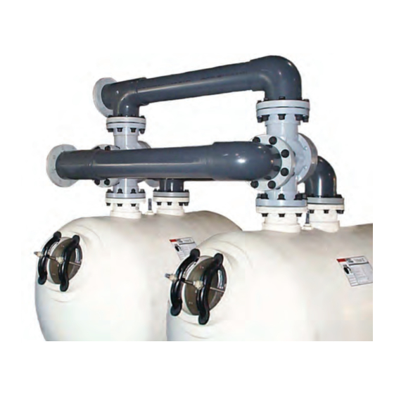
2.3 Dual Tank Face Piping Installation – THS 3461 (4” Grooved Tank Connections) The two tank face piping kit consists of: (2) 4” 3-way diaphragm valves (1) 6” 2-way diaphragm valve (2) Influent/effluent headers (1) Waste header (1) Sightglass assembly (not shown) (4) 4”... - Page 14 STEP 2: 4” 3-way Valve Installation Place a gasket of grooved coupling assembly on the influent grooved pipe connection of each tank. Place valves on influent grooved pipe connections, install groove coupling assembly(Refer to page 5). See picture at right for proper orientation.
- Page 15 STEP 4: Waste Header Installation Place gasket of grooved coupling assembly on grooved connection of influent valves. Install the waste extension on to the system as shown in picture. Install groove coupling assembly. Snug the nuts to “hand tight”, but do not fully tighten. STEP 5: 6”...
-
Page 16: (Ths 3484, Ths4272, Ths 4284 And Ths 4296)
STEP 7: Final Adjustments Once all piping is in place make any necessary adjustments and fully tighten all flange bolts. Be sure to follow the bolt tightening pattern explained at the beginning of Section 2.0. Tighten all Metallic type bolts to a maximum of 25 ft-lbs / Non Metallic to a maximum of 15 ft- lbs / Non Metallic. - Page 17 Owner’s/Operator’s Manual for more information. STEP 2: 6” 3-way Valve Installation Place a flange gasket on the influent flange of each tank. Align the holes in the gasket with the holes in the flange on the tank. Place valves on the influent flanges aligning the holes on the valve flange with the tank flange.
- Page 18 STEP 4: Waste Header Installation Place isoplast bolts through the flanges on the waste header, then place flange gaskets on to the flanges with the bolts. Install the waste header on to the remaining valve flanges making sure to align the flange holes with the bolts.
- Page 19 STEP 7: Final Adjustments Once all piping is in place make any necessary adjustments and fully tighten all flange bolts. Be sure to follow the bolt tightening pattern explained at the beginning of Section 2.0. Tighten all Metallic type bolts to a maximum of 25 ft-lbs / Non Metallic to a maximum of 15 ft- lbs / Non Metallic.
-
Page 20: Backwash Controller Installation
3 Backwash Controller Installation NOTE: This section covers the installation of semi-automatic and automatic backwash controllers for single tank and dual tank systems. 3.1 Semi-automatic Controller (CM200) - Single Tank Installation The single tank semi-automatic controller kit consists of the following: (1) Controller gauge panel (2) 3/8”... - Page 21 STEP 1: Controller Support Assembly Attach controller supports to the gauge panel assembly using the ¾” isoplast nuts and bolts. Attach so the channel side of the supports is away from the gauge panel. Tighten bolts, but do not over tighten, as this may crack the face of the gauge panel.
- Page 22 STEP 2A: Attach Gauge Panel to Pipe Insert notched end of pipe clamps into the channel of the controller supports. Attach the gauge panel assembly to the waste extension (see picture). Slide remaining pipe clamps into the channels of the controller supports. Use the nuts and bolts supplied to tighten the clamps on to the pipe.
- Page 23 STEP 3: Installation of Controller Tubing Connect length of tubing from supply source (water or compressed air) to the inlet side of the regulator. Please note, the water source must be able to supply water at a pressure of 35 psi minimum. Connect length of tubing from the outlet side of the regulator to the inlet end of the check valve.
- Page 24 Drill and tap for ¼” NPT hole on the influent and effluent pipes from the filter system (see schematic diagram in Appendix B). Install quick connect fittings into pipe. Be sure to use pipe thread sealant tape on the threads. Install 3/8”...
-
Page 25: Semi-Automatic Controller (Cm200) - Dual Tank Installation
3.2 Semi-Automatic Controller (CM200) – Dual Tank Installation The dual tank semi-automatic controller kit consists of the following: (1) Controller gauge panel (3) 3/8” OD tube quick connect tees (3) 3/8” OD x ¼” MNPT quick connect fittings (1) Check valve w/ fittings (1) And/Or Valve (100 ft) 3/8”... - Page 26 STEP 3: Installation of Controller Tubing Connect length of tubing from supply source (water or compressed air) to the inlet side of the regulator. Please note, the water source must be able to supply water at a pressure of 35 psi minimum. Connect length of tubing from the outlet side of the regulator to the inlet end of the check valve.
- Page 27 Drill and tap for ¼” NPT hole on the influent and effluent pipes from the filter system (see schematic diagram in Appendix B). Install quick connect fittings into pipe. Be sure to use pipe thread sealant tape on the threads. Install 3/8”...
-
Page 28: Automatic Controller (Ca100) - Single Tank Installation
3.3 Automatic Controller (CA100) - Single Tank Installation The single tank automatic controller kit consists of the following: (1) Automatic controller enclosure (1) Multiport valve enclosure (4) 3/8” OD tube quick connect tees (3) 3/8” OD x ¼” MNPT quick connect fittings (1) Check valve w/ fittings (100 ft) 3/8”... - Page 29 STEP 1: Attach Controller/Multiport Enclosures to Piping Insert notched end of pipe clamps into the channel of the enclosure supports. Attach the enclosure assemblies to the waste extension (see picture). Slide remaining pipe clamps into the channels of the enclosure supports. Use the nuts and bolts supplied to tighten the clamps on to the pipe.
- Page 30 Connect tubes to each side of the quick connect tee. Connect one tube to the multiport pressure gauge and the other to the center fitting on the multiport valve (see picture). Drill and tap for ¼” NPT hole on the influent and effluent pipes from the filter system (see schematic diagram in Appendix B).
- Page 31 Connect a length of tube from the open end of the quick connect tee from the valves to the fitting on the back of the multiport valve enclosure as shown in the picture. Connect tube from remaining quick connect fitting and connect to drain.
-
Page 32: Automatic Controller (Ca100) - Dual Tank Installation
3.4 Automatic Controller (CA100) – Dual Tank Installation The dual tank automatic controller kit consists of the following: (1) Automatic controller enclosure (1) Multiport valve enclosure (5) 3/8” OD tube quick connect tees (3) 3/8” OD x ¼” MNPT quick connect fittings (1) And/Or Valve (1) Check valve w/ fittings... - Page 33 STEP 1: Attach Controller/Multiport Enclosures to Piping Insert notched end of pipe clamps into the channel of the enclosure supports. Attach the enclosure assemblies to the waste extension (see picture). Slide remaining pipe clamps into the channels of the enclosure supports. Use the nuts and bolts supplied to tighten the clamps on to the pipe.
- Page 34 Connect tubes to each side of the quick connect tee. Connect one tube to the multiport pressure gauge and the other to the center fitting on the multiport valve (see picture). Drill and tap for ¼” NPT hole on the influent and effluent pipes from the filter system (see schematic diagram in Appendix B).
- Page 35 Connect tubes into respective fittings on the back of the multiport valve enclosure. Connect a tube from remaining quick connect fitting and connect to drain. Connect the four wires from the rear of the multiport valve enclosure to the rear of the automatic controller enclosure.
-
Page 36: Backwash Controller (Cs400) - Single Tank Installation
3.5 Backwash Controller (CS400) - Single Tank Installation The single tank backwash controller kit (CS400) consists of the following: (1) CS400 backwash controller enclosure (2) 3/8” OD tube quick connect tees (3) 3/8” OD x ¼” MNPT quick connect fittings (1) Check valve w/ fittings (100 ft) 3/8”... - Page 37 STEP 1: Attach Controller/Multiport Enclosures to Piping Insert notched end of pipe clamps into the channel of the backwash controller enclosure support. Attach the backwasher controller enclosure to the waste extension (see picture). Slide remaining pipe clamps into the channels of the enclosure support.
- Page 38 Connect tubes to each side of the quick connect tee. Connect one tube to the multiport pressure gauge and the other to the center fitting on the multiport valve (see picture). Drill and tap for ¼” NPT hole on the influent and effluent pipes from the filter system (see schematic diagram in Appendix B).
- Page 39 Connect a length of tube from the open end of the quick connect tee from the valves to the fitting on the back of the backwash controller enclosure as shown in the picture. Connect tube from remaining quick connect fitting and connect to drain.
-
Page 40: Backwash Controller (Cs400) - Dual Tank Installation
3.6 Backwash Controller (CS400) - Dual Tank Installation The dual tank backwash controller kit (CS400) consists of the following: (1) CS400 backwash controller enclosure (3) 3/8” OD tube quick connect tees (3) 3/8” OD x ¼” MNPT quick connect fittings (1) Check valve w/ fittings (1) And/Or Valve (100 ft) 3/8”... - Page 41 STEP 1: Attach Controller/Multiport Enclosures to Piping Insert notched end of pipe clamps into the channel of the backwash controller enclosure support. Attach the backwasher controller enclosure to the waste extension (see picture). Slide remaining pipe clamps into the channels of the enclosure support.
- Page 42 Connect tubes to each side of the quick connect tee. Connect one tube to the multiport pressure gauge and the other to the center fitting on the multiport valve (see picture). Drill and tap for ¼” NPT hole on the influent and effluent pipes from the filter system (see schematic diagram in Appendix B).
- Page 43 Connect tubes into respective fittings on the back of the backwash controller enclosure. Connect a tube from remaining quick connect fitting and connect to drain. This completes the installation of the backwash controller (CS400) for dual tank systems. Please see Owner’s/Operator’s Manual for backwash controller set up and operation. Diaphragm Valve Face Piping Kit Installation Manual Pg.
-
Page 44: Operation (Semi-Automatic Controller)
3.7 Operation (Semi-Automatic Controller) The diaphragm valve style face piping kits are designed for simple operation and maintenance. Backwashing is accomplished by turning a single knob to actuate the diaphragm valves. The automatic controller can be set up to backwash automatically dependant on certain chosen parameters, as well manually if required (refer to automatic controller manual for more information). - Page 45 The semi-automatic controller consists of a single gauge panel with gauges to measure influent and effluent pressures, water pressure supplied to the multiport valve, and the multiport valve knob, which is used to actuate the valves. The influent and effluent pressure gauges show the water pressure coming into and out of the filter system.
- Page 46 STEP 2: Verify that multiport pressure gauge returns to normal pressure. When actuating the valves the pressure to the multiport valve drops. When the valves become actuated the pressure gauge will begin to rise, and should return to its preset value (35 psi minimum). At this point, the valves are fully actuated. If the pressure does not return to its initial value, please consult the troubleshooting section of this manual.
- Page 47 Once system piping and proper valve installation is complete. Including hydraulic lines for valve activation. Hydro test system*. This must be done prior to adding media, start pump, allow system to fill with water to (bleed out all air). Run system for several minutes while doing this inspect for leaks and any unnecessary vibrations that can be reduced by additional support.
-
Page 48: Appendix
4 APPENDIX APPENDIX A TROUBLESHOOTING APPENDIX B CONTROLLER INSTALLATION SCHEMATICS APPENDIX C FILTER SYSTEM SPECIFICATION SHEETS APPENDIX D VALVE ASSEMBLY DRAWINGS Diaphragm Valve Face Piping Kit Installation Manual Pg. 47 of 52 5/31/12 Rev. F... - Page 49 APPENDIX A Problem Possible Cause Solution Verify that valve was installed correctly, making sure the arrow points in the proper direction. Refer to 1. Faulty or improperly installed check valve installation instructions for more information. Retry valve actuation. Verify that regulator was installed correctly. Refer to installation instructions for more information.
- Page 50 APPENDIX B Diaphragm Valve Face Piping Kit Installation Manual Pg. 49 of 52 5/31/12 Rev. F...
- Page 57 APPENDIX C Diaphragm Valve Face Piping Kit Installation Manual Pg. 50 of 52 5/31/12 Rev. F...
- Page 64 APPENDIX D Diaphragm Valve Face Piping Kit Installation Manual Pg. 51 of 52 5/31/12 Rev. F...
- Page 68 Pool and Spa, Inc. and/or its affiliated companies in the United States and/ or other countries. Unless expressly noted, names and brands of third parties that may be used in this document are not used to indicate an affiliation or endorsement between the owners of these names and brands and Pentair Water Pool and Spa, Inc. Those names and brands may be the trademarks or registered trademarks of those third parties.
Need help?
Do you have a question about the THS Series and is the answer not in the manual?
Questions and answers