Table of Contents
Advertisement
Quick Links
Advertisement
Table of Contents

Related Manuals for Ayrton huracan


Summary of Contents for Ayrton huracan
- Page 1 User Manual KEEP THIS MANUAL FOR FUTURE NEEDS...
-
Page 2: Table Of Contents
CONTENTS 1. SAFETY INSTRUCTIONS 2. FEATURES 3. FIXTURE OVERVIEW 4. DIMENSIONAL DRAWINGS 5. INSTALLATION INSTRUCTIONS 6. DMX-512 CONTROL CONNECTION 7. DMX-512 CONNECTION WITH DMX TERMINATOR 8. DEVICE DMX START ADDRESS SELECTION 9. OPERTING INSTRUCTIONS OF THE INTERNAL DMX WIRELESS SYSTEM 10. -
Page 3: Safety Instructions
1. SAFETY INSTRUCTIONS 1.1. IMPORTANT SAFETY WARNING This device has left the factory in perfect condition.In order to maintain this condition and to ensure safe operation,it is absolutely necessary for the user to follow the safety instructions and warning notes written in this user manual. In order to install,operate,and maintain the lighting fixture safely and correctly we suggest that the installation and operation be carried out by qualified technicians and these instructions be carefully followed. - Page 4 device from the mains.Only handle the power cord from the plug.Never pull the plug out of a socket by tugging the power cord. When powered on for the first time,some smoke or smell may occur.This is caused by coating on metal parts when heated and is normal.If you are concerned,please contact your distributor.
-
Page 5: Features
2. FEATURES POWER SUPPLY AC120-240V~,50/60Hz Power Consumption:1600W LIGHT SOURCE LED:White 1050W LED,8200±400K Color Temperature Extremely long Life:>20,000H MOVEMENT Pan movement:540º /630º Optional (16 bit) Tilt movement:270º (16 bit) Advanced moving system:fast,stable and quite,auto x-y repositioning COLORS ... - Page 6 Advanced RDM function WEIGHT Net weight:53.8 kg DMX CHANNEL CHART...
-
Page 7: Fixture Overview
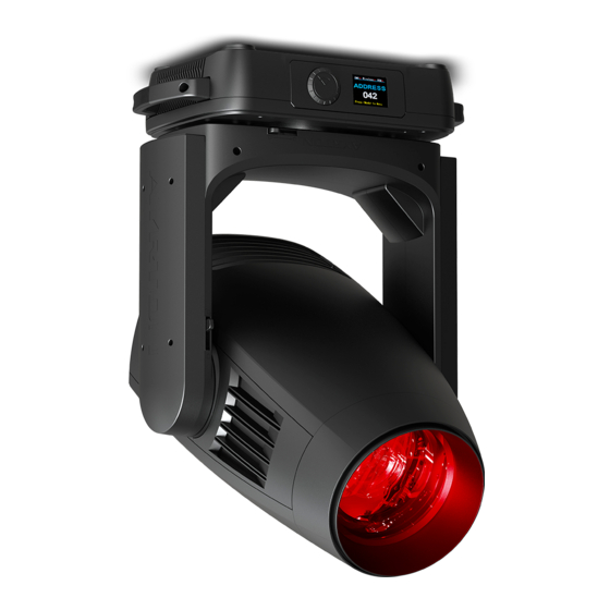
3. FIXTURE OVERVIEW 1) Lens 2) Tilt Lock 3) Display 4) Jog Wheel 5) Pan Lock 6) Handle 7) DMX Out 8) DMX In 9) USB 10) Power In 11) RJ45 Out 12) RJ45 In 13) Battery... -
Page 8: Dimensional Drawings
4. DIMENSIONAL DRAWINGS 4.1. Fixture Dimension... - Page 9 4.2. Color Filter Dimension 1. CTB1/4 (6.03.05.03.2864) 2. Congo Blue (6.03.05.03.2855) 3. Green (6.03.05.03.2856) 4. Orange (6.03.05.03.2857) 5. Blue (6.03.05.03.2858) 6. Red (6.03.05.03.2859)
- Page 10 4.3. Rotating Gobo Filter Dimension Rotating Gobo 1: 1. 314 – Dot Line 4 (6.03.03.05.1968) 2. 322 – Dot Ring 8 (6.03.03.05.1969) 3. 326 – Dot Triangle 3 (6.03.03.05.2026) 4. 332 – Square Beam 4 (6.03.03.05.1967) 5. 310 – Eccentric Dot (6.03.03.05.1970) 6.
- Page 11 Rotating Gobo 2: 1. 074 – Star Dust (6.03.03.01.1172-A) 2. 077 - Water (6.03.03.01.1575-0) 3. 275 – Prison Bars (6.03.03.01.1576-0) 4. 049 – Smoke Rings (6.03.03.01.1177-A) 5. 101 – Deep Forest (6.03.03.01.1182-0) 6. 105 – Tree Bark (6.03.03.01.1183-A) 7. 112Y – Nested Ring Yellow (6.03.03.06.0124)
- Page 12 4.4. Animation Filter Dimension...
-
Page 13: Installation Instructions
5. INSTALLATION INSTRUCTIONS 5.1. Rigging the device CAUTION! PLEASE CONSIDER THE RESPECTIVE NATIONAL NORMS DURING INSTALLATION. THE INSTALLATION MUST ONLY BE CARRIED OUT BY A QUALIFIED PERSON. The applicable temperature for the lighting is between -10° C to 45° C. Do not use the lighting under or above this temperature range. - Page 14 5.2. Rigging using the omega brackets Fix the clamp to the bracket by tightening the M12 nut and bolt to the bracket through the Ф13 hole in the middle of the bracket. Insert the quick-lock fasteners of the first Omega holder into the respective holes on the bottom of the device.Tighten the quick-lock fasteners fully clockwise.
- Page 15 5.3. RIGGING DRAWINGS Be sure this fixture is kept at least 0.1 m away from any flammable materials (decoration etc.). Always use and install the supplied safety cable as a safety measure to prevent accidental damage and/or injury in the event the clamp fails. Important:...
-
Page 16: Dmx-512 Control Connection
6. DMX-512 CONTROL CONNECTION Connect the provided male side of the XLR cable to the female XLR output of your controller and the female side of the XLR cable to the male XLR input of the device.You can connect multiple devices together in a serial fashion.The cable needed should be two core, screened cable with XLR input and output connectors.Please refer to the diagram below. -
Page 17: Device Dmx Start Address Selection
8. DEVICE DMX START ADDRESS SELECTION All fixtures should be given a DMX starting address when using a DMX signal,so that the correct fixture responds to the correct control signals.This digital starting address is the channel number from which the fixture starts to “ listen” to the digital control information sent out from the DMX controller.The allocation of this starting address is achieved by setting the correct address number on the display located on the base of the device. - Page 18 to DMX controller.After the fixture is power on,it can be controlled only by the DMX controller which connected.The fixture can log in the wireless transmitter,and receive only radio signal from transmitter,but not DMX from the transmitter. OFF:(De-activate WDMX) In this status,wireless system is not activated,so the fixture can not log in the transmitter. REST:(reset WDMX memory)...
-
Page 19: Display
10. DISPLAY The Display offers Jog wheel features:you can set the starting address,run the pre-programmed program or reset the device. The main menu is accessed by long pressing the jog wheel until the display starts flashing.Browse through the menu by turning jog wheel clockwise or counterclockwise. Double clicking in order to select the desired menu or long pressing to exit menu, double click for confirm.After accessing the edit mode,the unit will automatically exit to the Jog wheel... - Page 20 Service Password”=050” Service PIN Password=XXX Set Ip Set Ip xxx.xxx.xxx.xxx Set Mask Ip Set Mask Ip xxx.xxx.xxx.xxx DHCP Service PIN DHCP ON/OFF Cross Load SW Cross Load SW ON/OFF USB Update USB Update ON/OFF Clr LED Time Clr LED Time ON/OFF Auto Stage...
- Page 21 Network IP,Mask,Mac Network Reset All Pan&Tilt Reset Pan&Tilt Color Reset Color Home Gobo Reset Gobo Other Reset Others PAN …… Test Channel Test function PAN =XXX Manual Ctrl. Fine adjustment of the lamp Password “050” -Password- Calbrate and adjust the effects Calibration to standard/right position Gobo Wheel 1...
- Page 22 5.Long press the jog wheel to back to last button press – “User Mode” , then back to main menu by long press again. 10.2.2. Edit User Mode With this function,you can adjust the rest user defined channel order. 1.Double clicking jog wheel to access“USERS MODE”menu,turn the jog wheel until display“Edit User”.
- Page 23 6. Long press the jog wheel to back to last button press – “ Status” , then back to main menu by long press again. Pan Degree With this function,you can select pan degree for 630 or 540. 1. Double clicking jog wheel to access main menu. 2.
- Page 24 Reset Mode 1. Double clicking jog wheel to access main menu. 2. Turn the jog wheel clockwise then display“Options”. 3. Double click to access“Options” ,turn the jog wheel to select “Status”. 4. Double click to access“Status”menu,The display will show“Reset Mode”. 5.
- Page 25 1. Double clicking jog wheel to access main menu. 2. Turn the jog wheel clockwise then display“Options”. 3. Double click to access“Options” ,turn the jog wheel to select “Status”. 4. Double click to access“Status”menu,The display will show“Hibernation”. 5. Double click to access“Hibernation” ,The display will show “OFF” ,Turn the jog wheel to select“01M”...
- Page 26 5. Double click to access“DHCP” ,The display will show “OFF” ,Turn the jog wheel to select“ON”. 6. Long press the jog wheel to back to last button press – “ Service PIN” , then back to main menu by long press again. Cross Load SW 1.
- Page 27 Constant Fans 1.Double clicking jog wheel to access main menu. 2.Turn the jog wheel clockwise then display“Options”. 3.Double click to access“Options” ,turn the jog wheel to select “Fans Control”. 4.Double click to access “Fans Control” menu, The display will show “Constant Fans” . 5.Double click to access “Constant Fans”...
- Page 28 main menu by long press again. DispFlash With this function you can the entire display to be flipped by 180° to allow for better view when the fixture is hung from truss or a ceiling.This function is disabled as default. 1.Double clicking jog wheel to access main menu.
- Page 29 2. Turn the jog wheel clockwise then display“Options”. 3. Double click to access“Options” ,turn the jog wheel to select “Wireless DMX”. 4. Double click to access “ Wireless DMX” , The display will show “Activate WDMX” , Turn the jog wheel to select“Activate WDMX”,“Rest WDMX”. 5.
- Page 30 2. Turn the jog wheel clockwise then display“Options”. 3. Double click to access“Options” ,turn the jog wheel to select “Frost (Progressive)”. 4. Double click to access“Frost (Progressive)” ,The display will show “NO” ,Turn the jog wheel to select“OFF”. 5. Long press the jog wheel to back to last button press – “Gobo Correction” , then back to main menu by long press again.
- Page 31 3.Double click to access“Options” ,turn the jog wheel to select “Reset Default”. 4.Double click to access “Reset Default” menu, The display will show “OFF” , Turn the jog wheel to select“ON”. 5.Long press the jog wheel to back to last button press –“Reset Default” ,then back to main menu by long press again.
- Page 32 2. Turn the jog wheel clockwise then display“Info”. 3. Double click to access“Info” ,turn the jog wheel to select “Time Info.”. 4. Double click to access“Time Info.” ,The display will show “LED Hours”. 5. Double click to access“LED Hours” ,The display will show “XXXX (Hours)”. 6.
- Page 33 menu by long press again. 10.4.4. Software Ver With this function,you can display the software version of the device. 1. Double clicking jog wheel to access main menu. 2. Turn the jog wheel clockwise then display“Info”. 3. Double click to access“Info” ,turn the jog wheel to select “Software Ver”. 4.
- Page 34 2.Turn the jog wheel clockwise then display“Test”. 3.Double click to access“Test” ,turn the jog wheel to select “Manual control”. 4.Double click to access“Manual control” ,The display will show“PAN=XXX”. 5.Long press the jog wheel to back to last button press –“Test” ,then back to main menu by long press again.
- Page 35 host) 5.Enter the menu of 8-2 Edit Program---Edit Program.Edit the program’s connection, connect the scene in order 6.The editor of the scene,there are as many as 250 scenario editors,and every scene can have a program connection of 10. Note: Part 2,Part 3 repeat in accordance with the Part1’s repeat.For example:When Part 1 uses Program 2,Part 2 uses Program 4,Part 3 uses Program 6,Assume:Program 2 includes scene of 10,11,12,13;Program 4 includes scene of 8,9,10;Program 6 includes scene of 12,13,14,15;Then it will run as below.
-
Page 36: Dmx Protocol
11. DMX PROTOCOL DMX channel´ s functions and their values (70DMX channels): Mode/Channel Value Function PAN Movement 8bit : 0-255 Pan Movement Pan Fine 16bit 0-255 Fine control of Pan movement TILT Movement 8bit : 0-255 Tilt Movement Tilt Fine 16bit 0-255 Fine control of Tilt movement Speed Pan/Tilt movement:... - Page 37 201-255 AutoFocus Fine: 0-255 Continuous adjustment Fine Color Wheel: Open / white Color 1 8-11 Color 2 12-15 Color 3 16-19 Color 4 20-23 Color 5 24-27 Color 6 28-127 Color indexing 128-189 Forwards rainbow effect from fast to slow 190-193 No rotation 194-255...
- Page 38 Reserved Reserved Reserved Rotating gobos, cont. rotation 1: Open 10-19 Rot. gobo 1 20-29 Rot. gobo 2 30-39 Rot. gobo 3 40-49 Rot. gobo 4 50-59 Rot. gobo 5 60-69 Rot. gobo 6 70-77 Rot. Gobo 7 78-93 Gobo 1 shake slow to fast 94-109 Gobo 2 shake slow to fast 110-125...
- Page 39 142-157 Gobo 5 shake slow to fast 158-173 Gobo 6 shake slow to fast 174-189 Gobo 7 shake slow to fast 190-221 Gobo wheel rotation forwards from fast to slow 222-223 No rotation 224-255 Gobo wheel rotation f backwards from slow to fast Rotating gobo index,rotating gobo rotation 2: 0-127 Gobo indexing...
- Page 40 Prism 2: 0-127 Open 128-255 Prism 2 Rotating prism index, rotating prism rotation 2 0-127 Prism indexing 128-189 Forwards prism rotation from fast to slow 190-193 No rotation 194-255 Backwards prism rotation from slow to fast Rotating prism indexing Fine 2: 0-255 Fine indexing Frost 1:...
- Page 41 Blade 4B Fine 0-255 Open to Close Fine All Blade Rotation 0-255 All Blade Rotation All Blade Rotation Fine 0-255 All Blade Rotation Fine Control, reset, internal programs: unused Display Off 10-14 Display On 15-19 Display Invert Off 20-24 Display Invert On 25-26 Auto fan control mode 27-28...
- Page 42 Mode/Channel Value Function Domino Mode PAN Movement 8bit : 0-255 Pan Movement Pan Fine 16bit 0-255 Fine control of Pan movement TILT Movement 8bit : 0-255 Tilt Movement Tilt Fine 16bit 0-255 Fine control of Tilt movement Speed Pan/Tilt movement: 0-225 max to min speed 226-235...
- Page 43 Color 1 8-11 Color 2 12-15 Color 3 16-19 Color 4 20-23 Color 5 24-27 Color 6 28-127 Color indexing 128-189 Forwards rainbow effect from fast to slow 190-193 No rotation 194-255 Backwards rainbow effect from slow to fast Color Wheel Fine: 0-255 Color Wheel colour change to any position Fine CTB/CRI:...
- Page 44 110-125 Gobo 3 shake slow to fast 126-141 Gobo 4 shake slow to fast 142-157 Gobo 5 shake slow to fast 158-173 Gobo 6 shake slow to fast 174-189 Gobo 7 shake slow to fast 190-221 Gobo wheel rotation forwards from fast to slow 222-223 No rotation 224-255...
- Page 45 No rotation 8-127 Forwards rotation from fast to slow 128-135 No rotation 136-255 Backwards rotation from slow to fast Animation wheel 2: open 8-127 Forwards rotation from fast to slow 128-135 No rotation 136-255 Backwards rotation from slow to fast Iris: 0-191 Max.
- Page 46 0-255 Open to Close Fine Blade 2A : 0-255 Open to Close Blade 2A Fine 0-255 Open to Close Fine Blade 2B 0-255 Open to Close Blade 2B Fine 0-255 Open to Close Fine Blade 3A : 0-255 Open to Close Blade 3A Fine 0-255 Open to Close Fine...
- Page 47 61-63 64-69 70-74 Gobo correction Off 75-79 Gobo correction On 80-84 All motor reset 85-87 Scan motor reset 88-90 Colors motor reset 91-93 Gobo motor reset unused Reset P/T Fade Off Reset P/T Fade On 97-99 Other motor reset 100-102 Frost Progressive Off 103-105 Frost Progressive On...
- Page 48 EC068 SKY BLUE EC071 TOKIO BLUE EC075 EVENING BLUE EC079 JUST BLUE EC085 DEEPER BLUE EC088 LIME GREEN EC089 MOSS GREEN EC090 DARKYELLOW GREEN EC100 SPRING YELLOW EC101 YELLOW EC102 LIGHT AMBER EC103 STRAW EC104 DEEP AMBER EC105 ORANGE EC106 PRIMAY RED EC107 LIGHT ROSE...
- Page 49 EC158 DEEP ORANGE EC159 NO COLOR STRAW EC161 SLATE BLUE EC162 BASTARD AMBER EC164 FLAME RED EC165 DAYLIGHT BLUE EC169 LILAC TINT EC170 DEEP LAVENDER EC172 LAGOON BLUE EC174 DARK STEEL BLUE EC176 LOVING AMBER EC179 CHROME ORANGE EC180 DARK LAVENDER EC181 CONGO BLUE EC182...
-
Page 50: Error Messages
12. ERROR MESSAGES When you turn on the device, it will first perform a reset.The display may show“Err channel is XX”should there be problems with one or more functions.“XX” stands for channel 1,2,3, 4,5,6 etc whose sensor has encountered a problem.For example,when the display shows“Err channel is Pan movement”... - Page 51 Cyan Color wheel Er (Cyan Color wheel- error) This message will appear after the reset of the fixture if the head’s magnetic-indexing circuit malfunctions (sensor failed or magnet missing) or the stepper motor is defective (or its driving IC on the main PCB).The CMY - movement is not located in the default position after the reset.
- Page 52 Iris wheel Er (Iris wheel - error) This message will appear after the reset of the fixture if the head’s magnetic-indexing circuit malfunctions (sensor failed or magnet missing) or the stepper motor is defective (or its driving IC on the main PCB).The Iris - movement is not located in the default position after the reset.
- Page 53 (Blade 3 wheel - error) This message will appear after the reset of the fixture if the head’s magnetic-indexing circuit malfunctions (sensor failed or magnet missing) or the stepper motor is defective (or its driving IC on the main PCB).The Blade 3 - movement is not located in the default position after the reset.
-
Page 54: Cleaning And Maintenance
head’s magnetic-indexing circuit malfunctions (sensor failed or magnet missing) or the stepper motor is defective (or its driving IC on the main PCB).The Animation_Rot 1 - movement is not located in the default position after the reset. Animation_Rot 2 wheel Er (Animation_Rot 2 wheel - error) This message will appear after the reset of the fixture if the head’s magnetic-indexing circuit malfunctions (sensor failed or magnet missing) or the stepper motor is defective (or its driving IC on the main PCB).The Animation_Rot 2 - movement is not...
Need help?
Do you have a question about the huracan and is the answer not in the manual?
Questions and answers