Table of Contents
Advertisement
Quick Links
Advertisement
Table of Contents

Subscribe to Our Youtube Channel
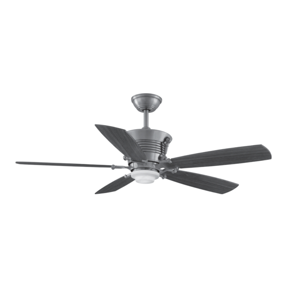
Summary of Contents for HAMPTON BAY Sabitini
-
Page 7: Hanging The Fan
Route the wires through the canopy and Hanging the Fan then through the ball/downrod assembly STANDARD CEILING REMEMBER to turn off the power. (Figure 7). MOUNTING Follow the steps below to hang your fan Loosen, but do not remove, the set Remove the canopy ring from the properly. -
Page 10: Making The Electrical Connections
from the fan. Making the Electrical Connections After wires are connected, carefully tuck them into the electrical box. Insert the REMEMBER to disconnect the power. If receiver unit into the mounting plate; you feel that you do not have enough make sure the black antenna wire sits on electrical wiring knowledge or experience, top of the receiver unit. -
Page 11: Finishing The Fan Installation
engage the slots and turn clockwise to Finishing lock in place. Immediately tighten the Installation two mounting screws firmly. WARNING STANDARD CEILING MOUNTING LOCKING SLOTS OF CEILING CANOPY ARE PROVIDED ONLY AS AN AID TO MOUNTING. WARNING LEAVE ASSEMBLY WHEN USING STANDARD UNATTENDED UNTIL ALL FOUR CANOPY... - Page 12 All blades are grouped by weight. polarized plugs (blue to black ; white to Because natural woods vary in density, white). Touching ceiling the fan may wobble even though the 3. Align the three screw holes on the blades are weight matched. black bracket with the holes on the top of the light kit fitter and secure with the The following procedure should correct...
- Page 13 hand unit controls directions (forward or reverse). Speed settings for warm or cool weather depend on factors such as the room size, ceiling height, number of fans, and so on. (Forward) Warm weather- downward air flow creates a cooling effect as shown in Figure 18. This allows you to set your air conditioner on a Figure 18 higher setting without affecting your...
-
Page 14: Operating Your Remote Control
Black Receiver Wire (AC IN L) Black Supply Wire Setting the Code White Receiver Wire(AC IN N) White Supply Wire White Receiver Wire(TO MOTOR N) White Fan Wire Black Receiver Wire(TO MOTOR L) Black Fan Wire This unit has 16 different code combinations. Blue Receiver Wire(FOR LIGHT) Blue Light Wire To set the code, perform the following steps. -
Page 15: Care Of Your Fan
Here are some suggestions to help you There is no need to oil your fan. maintain your fan. The motor has permanently lubricated Because fan's natural sealed ball bearings. movement, some connections become loose. Check the support WARNING connections, brackets, blade MAKE SURE THE POWER IS OFF AT THE attachments twice a year. -
Page 16: Troubleshooting
Problem Solution Fan will not start. 1. Check main and branch circuit fuses or breakers. 2. Check line wire connections to the fan and switch wire connections in the switch housing. CAUTION: Make sure main power is off. 3. Check battery in the transmitter. Does the red LED light come on? Are you standing close enough to the fan (normal range is 10-20 feet)? Are the dip switch settings the same on the transmitter (hand unit) and receiver? REMEMBER TO TURN OFF POWER SUPPLY BEFORE CHECKING THE DIP SWITCH SETTINGS IN RECEIVER. -
Page 17: Specifications
These are approximate measures. They do not include Amps and Wattage used by the light kit. Distributed by Your Other Warehouse, LLC 12100 Little Cayman Dr. Baton Rouge, LA 70809 2005 Homer TLC, Inc. All Rights Reserved Hampton Bay is a registered trademark of Homer TLC, Inc. 14.Specifications...


Need help?
Do you have a question about the Sabitini and is the answer not in the manual?
Questions and answers