Table of Contents
Advertisement
Quick Links
Advertisement
Table of Contents

Related Manuals for Cartft FleetPC-11 Series


Summary of Contents for Cartft FleetPC-11 Series
- Page 1 Edge AI GPU Computing FleetPC-11 Series User’s Manual V1.1...
- Page 2 Disclaimer CarTFT.com e.K. shall not be liable for any incidental or consequential damages resulting from the performance or use of this product. CarTFT.com e.K. makes no representation or warranty regarding the content of this manual. Information in this manual had been carefully checked for accuracy; however, no guarantee is given as to the correctness of the contents. For continuing product improvement, CarTFT.com e.K. reserves the right to revise the manual or make changes to the specifications of this product at any time without notice and obligation to any ...
- Page 3 All the trademarks, registrations and brands mentioned herein are used for identification purposes only and may be trademarks and/or registered trademarks of their respective owners. Safety Information Read the following precautions before setting up a CARTFT.COM E.K. Product. Electrical safety To prevent electrical shock hazard, disconnect the power cable from the electrical outlet before relocating the system. When adding or removing devices to or from the system, ensure that the power ...
- Page 4 CAUTION Incorrectly replacing the battery may damage this computer. Replace only with the same or its equivalent as recommended by CarTFT.com e.K. Dispose used battery according to the manufacturer's instructions. Technical Support Please do not hesitate to call or e‐mail our customer service when you still cannot fix ...
-
Page 5: Table Of Contents
2.1.2 LED Indicators ..........................2-1 2.1.3 FES-2SIM ............................2-2 2.1.4 HDMI Connectors (FLEETPC-11 Series) ..................2-2 2.1.5 LAN/PoE Ports ..........................2-3 2.1.6 SSD/HDD Holder ..........................2-3 Rear I/O Information ......................2-4 ... - Page 6 2.4.13 FES-2SIM SIM1/2 Connector ....................2-13 Board Connector Definition ..................... 2-14 2.5.1 MINI PCI-E 1 Slot (USB2.0 only) ....................2-14 2.5.2 MINI PCI-E 2 Slot (PCI-E&USB2.0) ....................2-15 2.5.3 MINI PCI-E 3 Slot (PCI-E&USB2.0) ....................2-16 ...
- Page 7 Enter The BIOS ........................5-1 Main ............................5-3 Advanced ..........................5-4 5.3.1 CPU Configuration ..........................5-4 5.3.2 ACPI Settings ............................. 5-6 5.3.3 Super I/O ............................5-8 5.3.4 CMS Configuration .......................... 5-10 ...
-
Page 8: Product Introduction
Chapter 1 Product Introduction... -
Page 10: Overview
1.0 Product Introduction 1.0 PRODUCT INTRODUCTION 1.1 Overview FLEETPC-11 is designed for a variety of performance demanding computing application in surveillance and field control systems. With new Intel Comet Lake 10th Gen Core i Processor’s exceptional performance, FLEETPC-11 effectively enables autonomous vehicles, factory automation and license plate recognition. ... -
Page 11: Specification
1.0 Product Introduction 1.3 Specification System Intel Gen10 Xeon W‐1290TE (20M Cache 2.0GHz up to 4.6GHz)* Intel Gen10 Core i9‐10900TE (20M Cache 2.0GHz up to 4.5GHz) Intel Gen10 Core i7‐10700TE (16M Cache 2.0GHz up to 4.4GHz) CPU Intel Gen10 Core i5‐10500TE (12M Cache 2.3GHz up to 3.7GHz) Intel Gen10 Core i3‐10100TE (6M Cache 2.3GHz up to 3.6GHz) Intel Gen10 Core G5900TE (4M Cache 3.0GHz) *Use only with Intel W480E Chipset Q470E/W480E 2 x DDR4 2666/2933 MHz SO‐DIMM up to 64GB (Optional ECC support Memory with Xeon W‐1290TE) 9 x Intel i210‐AT and 1 x i219 (support iAMT) Gb/s Ethernet Controllers Lan Chipset ... -
Page 12: Power Consumption
1.0 Product Introduction USB Port 4 x USB 3.2 Gen 1x1 Ports 10 x RJ45 Ports for GbE (Optional 8 with M12 X coded connectors and 8 x LAN PoE total Max.120W) Video Port 3 x DP (Intel built‐in GPU), 2 x HDMI Ports (MXM graphics) DIO Port 8 x DI (5~48VDC) and 4 x DO (5VDC, 100mA) Audio 1 x Line‐out, 1 x Line‐in and 1 x Mic‐in 2 x Full Mini‐PCle Slots and 1 x Full Mini‐PCIe Slot w/ USB interface only for WWAN sharing 2 x SIM Card Sockets with M.2 B Key 3042 slot Expansion Bus 1x M.2 A‐E Key 2230 slot, 1 x M.2 B Key 3042 slot w/ 2 x SIM Card Sockets for WWAN Environment & Mechanical Operating Temp. ‐40°C ~ 70°C w/ GTX 1650 (‐40ºC ~ 60ºC w/GTX 1060) w/0.6 m/S airflow Storage Temp. ‐40°C ~ 80°C Relative Humidity 10% RH – 90% RH (non‐condensing) IEC60068‐2‐64, random, 2.5G@5~500Hz, 1hr/axis Vibration (with SSD) MIL‐STD‐810G, Method 514.6, Procedure I, Cat.4, Operating Operating: MIL‐STD‐810G, Method 516.6, Procedure I, Shock Trucks and semi‐trailers=15G (11ms) with SSD Certifications CE, FCC Class A, E13, EN50155 M592609 ‐ Automatic SIM Card Detection Patent No. (Taiwan) M565941 ‐ Thermal Cooling M447854 ‐ Build‐in Battery Construction Aluminum Alloy Mounting ... - Page 13 1.0 Product Introduction Voltage 9V 12V 24V 48V Power Status S0 ( ) 12.91A 116.19W 10.65A 127.8W 5.24A 125.76W 2.70A 129.6W Burn‐In Test S0 (Idle) 5.40A 48.6W 6.09A 73.08W 2.25A 54W 1.29A 61.92W S3 0.43A 3.87W 0.32A 3.84W 0.20A 4.8W 0.19A 9.12W S5 0.34A ...
-
Page 14: Package Contents
Heatspreder for DDR SO‐DIMM 1 5 Screw I Type M2*5L ISO For fastening miniPCIe modules 6 6 Screw I Type M2.5x5L For fastening M.2 modules 3 1.6 Ordering Information See homepage 1.6 Optional Accessory CARTFT.COM provides optional accessories as follows. Please contact us or your dealer if you need any. Item Order No. Description DRAM 516016100910 SO‐DIMM 16GB DDR4‐2666 WT ADATA ‐40~85℃ DRAM 516008100310 SO‐DIMM 8GB DDR4‐2666 WT ADATA ‐40~85℃ DRAM 516004100910 SO‐DIMM 4GB DDR4‐2666 WT ADATA ‐40~85℃ M.2 SATA SSD 585100000020 SSD M.2 1TB 2280 SATA TLC WT w/ Thermal Kit Type 1 M.2 SATA SSD 585051200020 SSD M.2 512GB 2280 SATA TLC WT w/ Thermal Kit Type 1 M.2 SATA SSD 585025600020 SSD M.2 256GB 2280 SATA TLC WT w/ Thermal Kit Type 1 ... - Page 15 587906140010 (Antenna kit be included) VDB‐810 GPS kit, u‐blox M8 Engine, Concurrent Reception of GPS 610810080000 GPS/QZSS, GLONASS, BeiDou (GPS Active Antenna be included) VDB‐810G, u‐blox M8 Engine, Concurrent Reception of GPS 610810080001 GPS/QZSS, GLONASS, BeiDou and G‐sensor (GPS Active Antenna be included) VDB‐810DR, Embedded u‐blox NEO‐M8U GPS with Untethered GPS 618100080000 Dead Reckoning UDR & G‐Sensor Mini PCIe Card (GPS Active Antenna be included) WNFQ‐261ACNI(BT), 802.11ac 2T2R+BT5.0 M.2 2230 E Key, Wi‐Fi 580261090010 QCA6174A‐5 ‐40℃~ 85℃ (Wifi Antenna Kit be included) WNFT‐234ACN(BT) 802.11ac/b/g/n WiFi + Bluetooth M.2 Card, Wi‐Fi 580234090010 RTL8822BE, 2T2R 0~70C (wifi Antenna kit be included) BAT‐5200 Battery kit, 5200mAH 3S‐2P with charger board VIB‐ Battery kit 585200110000 5000 Power Adapter 549102428000 Power Adapter 24V/11.67A 280W with tin solder end *Please check with CARTFT.COM’ sales representatives for the availability User’s Manual Page 1-6...
-
Page 16: I/O And Connectors
Chapter 2 I/O and Connectors... -
Page 18: Front I/O Information
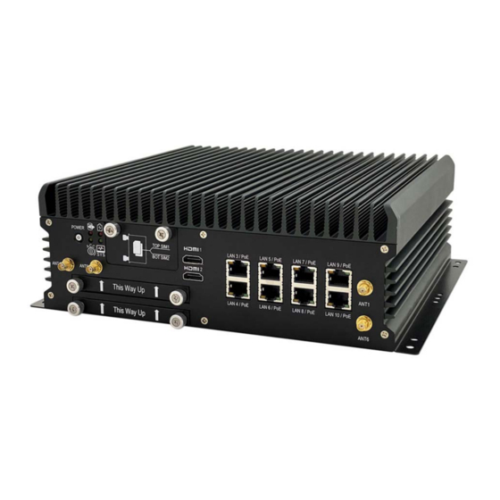
2.0 I/O and Connectors 2.0 I/O AND CONNECTORS 2.1 Front I/O Information 2.1.1 Power Button RED light: Standby BLUE light: Power On 2.1.2 LED Indicators HDD UPS Flash: one of storage Read/Write ON: UPS enable ACC System Status Flash: detection ON: System on Continue On: Ignition Ready OFF: System off User’s Manual Page 2-1... -
Page 19: Fes-2Sim
2.0 I/O and Connectors 2.1.3 FES‐2SIM Support SIM Card size: Mini SIM. SIM Card is switchable, but the default setting is on SIM CARD1. Please contact your CARTFT.COM’ sales representative to get the utility or software control for the SIM card switch function. Hot swappable design which allows SIM cards changing while system is in operating mode. Automatic 3G/LTE module reset after the FES‐2SIM module is inserted. ... -
Page 20: Lan/Poe Ports
2.0 I/O and Connectors 2.1.5 LAN/PoE Ports LAN/PoE Ports feature Intel i210‐AT and support 10/100/1000 Mbps LAN. Optional PoE support IEEE 802.3af and total max power is 100W budget. 2.1.6 SSD/HDD Holder Support: 2.5” and 9mm thickness Drive Bay for SATA Type HDD/SSD. When using 7mm thickness HDD/SSD, please insert HDD rubber (P/N:417290370250) which can be found in the accessories packet. ... -
Page 21: Rear I/O Information
2.0 I/O and Connectors 2.2 Rear I/O Information 2.2.1 Audio Jacks The system's audio function features high definition audio Realtek ALC662 codec. There are 3 female ports and a 3.5mm audio jack for mic‐in, line‐in, and line‐out. 2.2.2 DP Connectors Max resolution 4096x2304@60Hz from Intel UHD Graphics 630. User’s Manual Page 2-4... -
Page 22: Usb Connectors
2.0 I/O and Connectors 2.2.3 USB Connectors Support USB 3.0. 2.2.4 LAN Ports LAN1 features Intel i219 support 10/100/1000 Mbps and iAMT/PXE/Wake on. LAN2 features Intel i210‐AT support 10/100/1000 Mbps. User’s Manual Page 2-5... -
Page 23: Com Ports
2.2.5 COM Ports COM1 and COM2 port support RS 232/422/485, default setting is RS 232. COM3/CAN: default setting is COM3 and RS 232 (support RS 232/422/485 set by BIOS). Please contact the CARTFT.COM’ sales representative for optional CANBUS module. GPIO/COM4: default setting is GPIO. Please contact CARTFT.COM’ sales representative for optional COM4. 2.2.6 DC Input Terminal Block Ensure all 4 pins (Passive x 2 pins and Negative x 2pins) are used and connected to the input connector as in the drawing below. Missing pins may reduce lifetime of the ... -
Page 24: Illustration
2.0 I/O and Connectors IGN is for ignition control when installed in a Vehicle. Please see more detail for the ignition control at “4.2 Ignition Power Management Quick Guide” 2.3 Illustration 2.3.1 System Caution Sharp Edge Unit:mm User’s Manual Page 2-7... -
Page 25: Main Board
2.0 I/O and Connectors 2.3.2 Main Board Top View Caution Sharp Edge Unit:mm User’s Manual Page 2-8... - Page 26 2.0 I/O and Connectors Bottom View User’s Manual Page 2-9...
-
Page 27: I/O Connector Definition
2.0 I/O and Connectors 2.4 I/O Connector Definition 2.4.1 Audio Connector Pin Signal Pin Signal MIC_R MIC_JD GND 5 MIC_L 22 LINE OUT_R Connector size: 3 Pin x3 23 LINE OUT_JD 24 GND Connector type: 3.5mm Phone Jack x 3 25 LINE OUT_L 32 LINE IN_R Connector location: AUDIO1 33 LINE IN_JD 34 GND 35 LINE IN_L 2.4.2 DP1 Connector Pin ... -
Page 28: Dp3 Connector
2.0 I/O and Connectors 2.4.4 DP3 Connector Pin Signal Pin Signal 1 DP3_LANE_0P 2 GND Connector size: 20 Pin DP3_LANE_0N DP3_LANE_1P Connector type: Display Port DP3_LANE_1N Connector location: DP3 7 DP3_LANE_2P 8 GND 9 DP3_LANE_2N 10 DP3_LANE_3P 11 GND 12 DP3_LANE_3N 13 DP3_AUX_EN# 14 GND 15 DP3_AUXP/LK 16 GND 17 ... -
Page 29: Usb3.0_3/4 Connector
2.0 I/O and Connectors Connector size: 9 Pin x2 3 USB_DP 4 GND Connector type: USB3.0 Type A x2 USB3_SSRX_DN USB3_SSRX_DP Connector location: LANUSB1 USB3_SSTX_DN 9 USB3_SSTX_DP 2.4.8 USB3.0_3/4 Connector Signal Signal +5VSB USB_DN USB_DP GND Connector size: 9 Pin x2 5 USB3_SSRX_DN 6 USB3_SSRX_DP Connector type: USB3.0 Type A x2 7 GND 8 USB3_SSTX_DN Connector location: LANUSB2 9 USB3_SSTX_DP ... -
Page 30: Dc Power Connector
2.0 I/O and Connectors 2.4.11 DC Power Connector Pin Signal Pin Signal 1 GND 2 GND Connector size: 1x5 Pin 3 DC_IN(+9~+48V) 4 DC_IN(+9~+48V) Connector type: DECA 5mm‐F‐90D‐5PIN 5 Ignition Connector location: Power1 2.4.12 HDMI1/2 Connector Pin Signal Pin Signal 1 TMDS Data2+ 2 GND 3 TMDS Data2‐ 4 TMDS Data1+ Connector size: 19 Pin 5 ... -
Page 31: Board Connector Definition
2.0 I/O and Connectors 2.5 Board Connector Definition 2.5.1 MINI PCI‐E 1 Slot (USB2.0 only) Pin Signal Pin Signal PCIE_WAKE# +3.3VSB GND 5 NC 6 NC 7 NC 8 UIM_PWR_B 9 GND 10 UIM_DAT_B Connector size: 2 X 26 = 52 Pin 11 NC 12 UIM_CLK_B Connector type: MINI PCI‐E CON 9.2mmH 13 NC 14 UIM_RST_B Connector location: MINICARD1 15 GND 16 ... -
Page 32: Mini Pci-E 2 Slot (Pci-E&Usb2.0)
2.0 I/O and Connectors 2.5.2 MINI PCI‐E 2 Slot (PCI‐E&USB2.0) Pin Signal Pin Signal PCIE_WAKE# 2 +3.3VSB 4 GND 6 +1.5V 7 MINICARD2_CLKREQ# 8 NC 9 GND 10 NC 11 PCIE_MCARD2_CLK_DN 12 NC Connector size: 2 X 26 = 52 Pin 13 PCIE_MCARD2_CLK_DP 14 NC Connector type: MINI PCI‐E CON 9.2mmH 15 GND 16 NC Connector location: MINICARD2 ... -
Page 33: Mini Pci-E 3 Slot (Pci-E&Usb2.0)
2.0 I/O and Connectors 2.5.3 MINI PCI‐E 3 Slot (PCI‐E&USB2.0) Pin Signal Pin Signal PCIE_WAKE# 2 +3.3VSB 4 GND 6 +1.5V 7 MINICARD3_CLKREQ# 8 NC 9 GND 10 NC Connector size: 2 X 26 = 52 Pin 11 PCIE_MCARD3_CLK_DN 12 NC Connector type: MINI PCI‐E CON 9.2mmH 13 PCIE_MCARD3_CLK_DP 14 NC Connector location: MINICARD3 15 GND 16 NC 17 ... -
Page 34: Ngff1 Slot (Pci-E&Usb2.0)
2.0 I/O and Connectors 2.5.4 NGFF1 slot (PCI‐E&USB2.0) Pin Signal Pin Signal 1 GND 2 +3.3VSB 3 USB_10P 4 +3.3VSB USB_10N NC NC 9 NC 10 NC Connector size: 2230 11 NC 12 NC Connector type: NGFF _AE KEY_H:8.5mm 13 NC 14 NC Connector location: NGFF1 15 NC 16 NC 17 ... -
Page 35: Ngff2 Slot (Pci-Ex4/Satax1)
2.0 I/O and Connectors 71 NC 72 +3.3VSB +3.3VSB 2.5.5 NGFF2 slot (PCI‐Ex4/SATAx1) Pin Signal Pin Signal 1 GND 2 +3.3V 3 GND 4 +3.3V User’s Manual Page 2-18... - Page 36 2.0 I/O and Connectors Connector size: 2280 5 PCIE_M.2_RX_20N 6 NC Connector type: NGFF _M KEY_H:8.5mm 7 PCIE_M.2_RX_20P 8 NC Connector location: NGFF2 9 GND 10 DAS/DSS# PCIE_M.2_TX_20N +3.3V PCIE_M.2_TX_20P +3.3V +3.3V PCIE_M.2_RX_19N +3.3V 19 PCIE_M.2_RX_19P 20 NC 21 GND 22 NC 23 PCIE_M.2_TX_19N 24 NC 25 PCIE_M.2_TX_19P 26 ...
-
Page 37: Ngff3 Slot (Pci-E&Usb3.0&2.0)
2.0 I/O and Connectors 2.5.6 NGFF3 slot (PCI‐E&USB3.0&2.0) Pin Signal Pin Signal CONFIG3 +3.3VSB +3.3VSB PWR_OFF_1.8V 7 USB_5P 8 M.2_DIS1# 9 USB_5N 10 M.2WWLANLED# Connector size: 3042 11 GND 12 KEY Connector type: NGFF _B KEY_H:8.5mm 13 KEY 14 KEY Connector location: NGFF3 15 KEY 16 KEY 17 KEY 18 ... -
Page 38: Dio1 Jst Connector
2.0 I/O and Connectors 2.5.7 DIO1 JST Connector Pin Signal Pin Signal 1 D0_1 (+5V‐100mA) 2 D0_2 (+5V‐100mA) D0_3 (+5V‐100mA) D0_4 (+5V‐100mA) Connector size: 2 X 8 = 16 Pin GND Connector type: JST‐2.0mm‐M‐180 7 DI_1 (+5V~48V ) 8 DI_2 (+5V~48V ) Connector location: DIO1 9 DI_3 (+5V~48V ) 10 DI_4 (+5V~48V ) 11 DI_5 (+5V~48V ) 12 DI_6 (+5V~48V ) 13 DI_7 (+5V~48V ) 14 DI_8 (+5V~48V ) 15 GND ... -
Page 39: Sata1 Connector
2.0 I/O and Connectors Connector size: 2 X 4 = 8 Pin Connector type: JST‐2.0mm‐M‐180 Connector location: USB1 2.5.11 SATA1 Connector Pin Signal 1 GND 2 SATA_TXP1 3 SATA_TXN1 4 GND 5 SATA_RXN1 Connector size: 1 X 7 = 7 Pin 6 SATA_RXP1 Connector type: SATA 1.27mm‐M‐180D 7 GND Connector location: SATA1 2.5.12 SATA2 Connector Pin Signal 1 GND 2 SATA_TXP2 SATA_TXN2 SATA_RXN2 Connector size: 1 X 7 = 7 Pin 6 ... -
Page 40: Ups1 Jst Connector
2.0 I/O and Connectors 2.5.14 UPS1 JST Connector Pin Signal +12V UPS +12V UPS 4 GND 5 SCLK Connector size: 1 X 6 = 6 Pin 6 SDA Connector type: WAFER 2.0mm‐M‐180 Connector location: UPS1 2.5.15 UPS2 JST Connector Pin Signal 1 DC IN 2 DC IN 3 GND 4 GND Connector size: 1 X 4 = 4 Pin Connector type: WAFER 2.0mm‐M‐180 Connector location: UPS2 2.5.16 BAT1 Power Connector Pin Signal 1 BAT +3V 2 GND ... -
Page 41: Cn1 Jst Connector
2.0 I/O and Connectors 2.5.18 CN1 JST Connector Signal Signal Connector size: 2 X 15 = 30 Pin +3.3VSB UIM_RESET1 Connector type: P0.5mm‐FM‐90,H=9mm GND Connector location: CN1 5 USB‐D6P 6 UIM_CLK1 7 USB‐D6N 8 GND 9 GND 10 UIM_DATA1 11 +5VSB 12 GND 13 GND 14 UIM_PWR1 15 DET LOW 16 SIM_DET 17 NC 18 ... -
Page 42: Fes-2Sim Cn1 Jst Connector
2.0 I/O and Connectors 2.5.19 FES‐2SIM CN1 JST Connector Pin Signal Pin Signal UIM_RESET1 GND UIM_CLK1 7 NC 8 GND 9 GND 10 UIM_DATA1 11 NC 12 GND 13 GND 14 UIM_PWR1 15 SIM_DET 16 SIM_DET 17 NC 18 UIM_RESET2 19 GND 20 GND 21 ... -
Page 43: Mxmgf1 Connector
2.0 I/O and Connectors A17 PSE_OUT3 B17 GND_C A18 PSE_AGND B18 GND_C A19 PSE_OUT4 B19 GND_C A20 PSE_AGND B20 GND_C A21 PSE_OUT5 B21 GND_C A22 PSE_AGND B22 GND_C A23 PSE_OUT6 B23 GND_C A24 PSE_AGND B24 GND_C A25 PSE_OUT7 B25 GND_C A26 PSE_AGND ... - Page 44 2.0 I/O and Connectors 31 NC 32 SMB_DAT 33 NC 34 SMB_CLK 35 NC 36 GND 38 NC 40 NC 42 NC 44 NC 45 NC 46 GND 47 GND 48 TX_15_N 49 RX_15_N 50 TX_15_P 51 RX_15_P 52 GND 53 ...
- Page 45 2.0 I/O and Connectors 115 RX_4_N 116 TX_4_P 117 RX_4_P 118 GND 119 GND 120 TX_3_N 121 RX_3_N 122 TX_3_P 123 RX_3_P 124 GND 125 GND 126 KEY 127 KEY 128 KEY 129 KEY 130 KEY 131 KEY 132 KEY 133 GND ...
- Page 46 2.0 I/O and Connectors 199 NC 200 NC 201 NC 202 NC 203 GND 204 GND 205 NC 206 NC 207 NC 208 NC 209 GND 210 GND 211 NC 212 NC 213 NC 214 NC 215 GND 216 GND 217 NC ...
- Page 47 2.0 I/O and Connectors User’s Manual Page 2-30...
-
Page 48: System Setup
Chapter 3 System Setup... -
Page 50: Opening The Chassis
3.0 System Setup 3.0 SYSTEM SETUP 3.1 Opening the Chassis Step 1. Unscrew the six screws on the back cover as shown in the picture. Step 2. Unscrew the three screws on the front panel as shown in the picture. User’s Manual Page 3-1... - Page 51 3.0 System Setup Step 3. Unscrew the one screw on the rear panel as shown in the picture. Step 4. Untighten the storage bracket screws on the front panel as shown in the picture. User’s Manual Page 3-2...
- Page 52 3.0 System Setup Step 5. Remove bottom cover as shown in the picture. User’s Manual Page 3-3...
-
Page 53: Installing Memory
3.0 System Setup 3.2 Installing Memory Step 1. Insert the memory module into the slot as shown in the picture. Step 2. Stick the poron (P/N: 417290362120) on the memory slot as shown in the picture. User’s Manual Page 3-4... - Page 54 3.0 System Setup Step 3. Hold the memory module with its notch aligned with the memory slot on the motherboard and insert the memory module into the slot at a 30‐degree angle as shown in the picture. Step 4. Tilt the memory module so that it can be fixed with both memory lock stoppers as shown in the picture. User’s Manual Page 3-5...
- Page 55 3.0 System Setup Step 5. Complete as shown in the picture. Step 6. Stick the pad (P/N: 265024060010) on the heatsink (P/N: 263097072190) as shown in the picture. User’s Manual Page 3-6...
- Page 56 3.0 System Setup Step 7. Stick the pad (P/N: 265018070010) on the memory heatsink as shown in the picture. Step 8. Put the heatsink on the memory module and screw the one screw to the holder (P/N: 351103060810) as shown in the picture. User’s Manual Page 3-7...
-
Page 57: Installing Mini Pcie Expansion Card (Minicard 1, 3G/Lte)
3.0 System Setup 3.3 Installing MINI PCIe Expansion Card (Minicard 1, 3G/LTE) Step 1. Insert MINI PCIe Expansion Card into the Slot as shown in the picture. User’s Manual Page 3-8... - Page 58 3.0 System Setup Step 2. Hold the Module with its notch aligned with the Slot on the motherboard and insert the Module into the Slot at a 30‐degree angle as shown in the picture. Step 3. Screw the two screws (P/N:351103040250) to the holder as shown in the picture. User’s Manual Page 3-9...
-
Page 59: Installing Mini Pcie Expansion Card (Minicard 2)
3.0 System Setup Step 4. Complete as shown in the picture. 3.4 Installing MINI PCIe Expansion Card (MiniCard 2) User’s Manual Page 3-10... - Page 60 3.0 System Setup Step 1. Insert MINI PCIe Expansion Card into this Slot as shown in the picture. Step 2. Hold the Module with its notch aligned with the Slot on the motherboard and insert the Module into the Slot at a 30‐degree angle as shown in the picture. Step 3. Screw the one screw to the holder as shown in the picture. User’s Manual Page 3-11...
- Page 61 3.0 System Setup Step 4. Complete as shown in the picture. User’s Manual Page 3-12...
-
Page 62: Installing Mini Pcie Expansion Card (Minicard 3)
3.0 System Setup 3.5 Installing MINI PCIe Expansion Card (MiniCard 3) Step 1. Insert MINI PCIe Expansion Card into this Slot as shown in the picture. Step 2. Hold the Module with its notch aligned with the Slot on the motherboard and insert the Module into the Slot at a 30‐degree angle as shown in the picture. User’s Manual Page 3-13... - Page 63 3.0 System Setup Step 3. Screw the two screws to the holder as shown in the picture. Step 4. Complete as shown in the picture. User’s Manual Page 3-14...
-
Page 64: Installing M.2 Module
3.0 System Setup 3.6 Installing M.2 Module Step 1. Insert M.2 module into this Slot as shown in the picture. Step 2. Hold the Module with its notch aligned with the Slot on the motherboard and insert the Module into the Slot at a 30‐degree angle as shown in the picture. User’s Manual Page 3-15... - Page 65 3.0 System Setup Step 3. Screw one screw (P/N:351103060810) to the holder as shown in the picture. Step 4. Complete as shown in the picture. User’s Manual Page 3-16...
- Page 66 3.0 System Setup Step 5. Take the Ipex Connector and press on the M.2 module as shown in the picture. User’s Manual Page 3-17...
-
Page 67: Installing M.2 Module (3G/Lte)
3.0 System Setup 3.7 Installing M.2 Module (3G/LTE) Step 1. Insert MINI PCIe Expansion Card into the Slot as shown in the picture. Step 2. Hold the Module with its notch aligned with the Slot on the motherboard and insert the Module into the Slot at a 30‐degree angle as shown in the picture. User’s Manual Page 3-18... - Page 68 3.0 System Setup Step 3. Screw the one screw to the holder as shown in the picture. Step 4. Complete as shown in the picture. User’s Manual Page 3-19...
-
Page 69: Installing M.2 Nvme Ssd
3.0 System Setup 3.8 Installing M.2 NVMe SSD Step 1. Insert NVMe SSD into this Slot as shown in the picture. User’s Manual Page 3-20... - Page 70 3.0 System Setup Step 2. Stick the two Silicone Rubbers (P/N: 417290310101) on the mainboard as shown in the picture. Step 3. Stick the Thermal Pad to the heatsink (P/N: 268104022240) as shown in the picture. Step 4. Hold the SSD with its notch aligned with the Slot on the motherboard and insert the Module into the Slot at a 30‐degree angle as shown in the picture. User’s Manual Page 3-21...
- Page 71 3.0 System Setup Step 5. Put the heatsink on the module and screw the one screw to the holder (P/N: 351125100110) as shown in the picture. User’s Manual Page 3-22...
-
Page 72: Installing M.2 Sata Ssd
3.0 System Setup Step 6. Screw the one screw (P/N: 35110306810) to the holder as shown in the picture. 3.9 Installing M.2 SATA SSD Step 1. Insert NVMe SSD into this Slot as shown in the picture. User’s Manual Page 3-23... - Page 73 3.0 System Setup Step 2. Stick the two Silicone Rubbers (P/N: 417290310102) on the mainboard as shown in the picture. Step 3. Stick the Thermal Pad to the heatsink (P/N: 268104022240) as shown in the picture. User’s Manual Page 3-24...
- Page 74 3.0 System Setup Step 4. Hold the SSD with its notch aligned with the Slot on the motherboard and insert the Module into the Slot at a 30‐degree angle as shown in the picture. Step 5. Put the heatsink on the module and screw the one screw to the holder (P/N: 351125100110) as shown in the picture. User’s Manual Page 3-25...
- Page 75 3.0 System Setup Step 6. Screw the one screw (P/N: 35110306810) to the holder as shown in the picture. User’s Manual Page 3-26...
-
Page 76: Installing Internal Antenna Cable
3.0 System Setup 3.10 Installing Internal Antenna Cable Step 1. Take the SMA Connector and Plug into IO Panel as shown in the picture. Step 2. Put the Washer into the SMA Connector as shown in the picture. User’s Manual Page 3-27... - Page 77 3.0 System Setup Step 3. Put the O‐ring to the SMA Connector and tighten it as shown in the picture. Step 4. Complete as shown in the picture. User’s Manual Page 3-28...
- Page 78 3.0 System Setup Step 5. Take the Ipex Connector and press on the 3G module as shown in the picture. (3G/LTE) User’s Manual Page 3-29...
- Page 79 3.0 System Setup Step 6. Take the Ipex Connector and press on the WiFi module as shown in the picture.(WiFi) User’s Manual Page 3-30...
- Page 80 3.0 System Setup Step 7. Take the Ipex Connector and press on the GPS module as shown in the picture. (GPS) User’s Manual Page 3-31...
-
Page 81: Installing Sim Card
3.0 System Setup 3.11 Installing SIM Card Step 1. Loosen the SIM Card bracket screws as shown in the picture. Step 2. Take the SIM Card bracket away from front panel as shown in the picture. User’s Manual Page 3-32... - Page 82 3.0 System Setup Step 3. Put your SIM Card into the bracket as shown in the picture. Step 4. Push the SIM Card bracket into the socket as shown in the picture. User’s Manual Page 3-33...
- Page 83 3.0 System Setup Step 5. Fully insert the SIM Card bracket into the socket until you hear a “click” as shown in the picture. User’s Manual Page 3-34...
- Page 84 3.0 System Setup Step 6. Tighten the SIM Card bracket screws as shown in the picture. Step 7. Complete as shown in the picture. User’s Manual Page 3-35...
-
Page 85: Installing Hdd
3.0 System Setup Attention: When insert a SIM card to the SIM card holder, please remove the main power at input to avoid undetectable SIM card. 3.12 Installing HDD Step 1. Put the HDD bracket on the bottom cover as shown in the picture. User’s Manual Page 3-36... - Page 86 3.0 System Setup Step 2. Turn over the bottom cover and screw the four screws as shown in the picture. Step 3. Take SATA cable into the SATA bracket as shown in the picture. User’s Manual Page 3-37...
- Page 87 3.0 System Setup Step 4. Screw two screws (one HDD) or four screws (two HDD) as shown in the picture. Step 5. Put SATA bracket on the bottom cover and screw the two screws as shown in the picture. User’s Manual Page 3-38...
- Page 88 3.0 System Setup Step 6. Turn over the bottom cover and screw the two screws as shown in the picture. Step 7. Connect SATA cable to motherboard (SATA1 to SPWR1, SATA2 to SPWR2) as shown in the picture. User’s Manual Page 3-39...
- Page 89 3.0 System Setup Step 8. Put the HDD into HDD Holder as shown in the picture. User’s Manual Page 3-40...
- Page 90 3.0 System Setup Step 9. This rubber (P/N:417290370250) is used only for a thickness of 7mm SSD/HDD. Please stick this rubber at the side without golden fingers as the indicated position as shown in the picture. Step 10. Screw the two screws (P/N:351103040250) on both sides as shown in the picture. User’s Manual Page 3-41...
- Page 91 3.0 System Setup Step 11. Push the HDD Holder into the socket as shown in the picture. Step 12. Fully insert the HDD Holder into the socket until you hear a “click” as shown in the picture. User’s Manual Page 3-42...
- Page 92 3.0 System Setup Step 13. Tighten the Storage Bracket screws as shown in the picture. Step 14. Complete as shown in the picture. User’s Manual Page 3-43...
-
Page 93: Installing Poe Module
3.0 System Setup 3.13 Installing POE Module Step 1. Insert POE Module into this Slot as shown in the picture. User’s Manual Page 3-44... - Page 94 3.0 System Setup Step 2. Insert the POE‐8P module into the motherboard as shown in the picture Step 3. Put the Heatsink on the POE module as shown in the picture Step 4. Screw the four screws (P/N:351103151810) as shown in the picture User’s Manual Page 3-45...
- Page 95 3.0 System Setup Step 5. Complete as shown in the picture User’s Manual Page 3-46...
-
Page 96: Installing Battery Module (Only For Optional Bat-5200 Kit)
3.0 System Setup 3.14 Installing Battery Module (only for optional BAT‐5200 Kit) Step 1. VIB‐5000 board t as shown in the picture. User’s Manual Page 3-47... - Page 97 3.0 System Setup Step 2. Take 6pin cable into UPS3 socket & 4pin cable into UPS4 socket on VIB‐5000 Board as shown in the picture. Step 3. Connect the battery with VIB‐5000 on BAT‐1 Socket as shown in the picture. Step 4. BAT‐5100 battery bracket as shown in the picture. User’s Manual Page 3-48...
- Page 98 3.0 System Setup Step 5. Put the battery and VIB‐5000 board into the bracket and screw four screws as shown in the picture. User’s Manual Page 3-49...
- Page 99 3.0 System Setup Step 6. Take the battery kit and screw four screws into the back cover as shown in the picture. Step 7. Connect the battery kit with motherboard on UPS1(6pin) & UPS2(4pin) location as shown in the picture. User’s Manual Page 3-50...
-
Page 100: System Resource
Chapter 4 System Resource... -
Page 102: Gpio Control Register
4.0 System Resource 4.0 SYSTEM RESOURCE 4.1 GPIO Control Register Hardware Specification Model GPI voltage GPO voltage DO max current FLEETPC‐11 5‐48V 5V 100mA Digital Output and External Relay Recommend Circuit Register Definitions DO Data Register – 0x31 Bit Name R/W DESCRIPTION 3 GPIO4_OUT R/W GPIO4 output data. 2 GPIO3_OUT R/W GPIO3 output data. 1 GPIO2_OUT R/W GPIO2 output data. 0 GPIO1_OUT R/W GPIO1 output data. ... -
Page 103: Ignition Power Management Quick Guide
4.2 Ignition Power Management Quick Guide Startup conditions from the IGNITION signal: IGNITION startup signal must be valid during 3 sec. (anti noise protection). Typically the system can start only from IGNITION signal, because startup PIC controller is disconnected from the power source. Startup Procedure by Ignition IGN on (High) 9VDC~48VDC Check IGN System Turn more than Power Input Status 3sec Startup Procedure by Power Button 9VDC~48VDC Push Power System Turn Power Input Button Technical Support Please do not hesitate contact with CARTFT.COM E.K. for API and utility when you still cannot fix the problems. Tel : +49 7121 3878264 Fax : +49 7121 3878265 E‐mail : sales@cartft.com Website : www.CarTFT.com User’s Manual Page 4-2... -
Page 104: Bios Setting
Chapter 5 BIOS Setting... -
Page 105: Enter The Bios
5.0 BIOS Setting 5.0 BIOS SETTING 5.1 Enter The BIOS Power on the computer and the system will start POST (Power On Self Test) process. When the message below appears on the screen, press (DEL) key to enter Setup. Press DEL to enter SETUP If the message disappears before you respond and you still wish to enter Setup, restart the system by turning it OFF and On or pressing the RESET button. You may also restart the system by simultaneously pressing <Ctrl>, <Alt>, and <Delete> keys. Important The items under each BIOS category described in this chapter are under continuous update for better system performance. Therefore, the description may be slightly different from the latest BIOS and should be held for reference only. Upon boot‐up, the 1st line appearing after the memory count is the BIOS version. It is usually in the format. Control Keys Power on the computer and the system will start POST (Power On Self Test) process. When the message below appears on the screen, press (DEL) key to enter Setup. ... - Page 106 5.0 BIOS Setting Getting Help After entering the Setup menu, the first menu you will see is the Main Menu. Main Menu The main menu lists the setup functions you can make changes to. You can use the arrow keys (↑↓) to select the item. The on‐line description of the highlighted setup function is displayed at the bottom of the screen. Sub‐Menu If ...
-
Page 107: Main
5.0 BIOS Setting 5.2 Main System Date This setting allows you to set the system Date. The time format is <Day> <Month> <Date> <Year>. System Time This setting allows you to set the system time. The time format is <Hour> <Minute> <Second>. ... -
Page 108: Advanced
5.0 BIOS Setting 5.3 Advanced 5.3.1 CPU Configuration Turbo Mode Hyper‐Threading Allows you to enable or disable Intel® Hyper‐Threading function of processor. User’s Manual Page 5-4... - Page 109 5.0 BIOS Setting Intel (VMX) Virtualization Technology Enables or disables Intel® Virtualization Technology. Virtualization enhanced by Intel® Virtualization Technology will allow a platform to run multiple operating systems and applications in independent partitions. With virtualization, one computer system can function as multiple virtual systems. User’s Manual Page 5-5...
-
Page 110: Acpi Settings
5.0 BIOS Setting 5.3.2 ACPI Settings This item allows users to configure ACPI settings. Enable ACPI Auto Configuration Enables or disables BIOS Advanced Configuration Power Interface® (ACPI) auto configuration. User’s Manual Page 5-6... - Page 111 5.0 BIOS Setting ACPI Sleep State Allows users to select the highest Advanced Configuration Power Interface® (ACPI) sleep state that system will enter when suspend button is pressed. S3 Video Repost User’s Manual Page 5-7...
-
Page 112: Super I/O
5.0 BIOS Setting 5.3.3 Super I/O The screen allows users to select options for the Super IO configuration, and change the value of the selected option. Serial Port Configuration User’s Manual Page 5-8... - Page 113 5.0 BIOS Setting Serial Port 1/2/3/4 Enable or Disable Select an Enable or Disable for the specified serial ports. COM1 RS232/422/485 Select User’s Manual Page 5-9...
-
Page 114: Cms Configuration
5.0 BIOS Setting Watch Dog Function 5.3.4 CMS Configuration This item allows users to enable or disable UEFI Compatibility Support Module (CSM) to support a legacy PC boot process. User’s Manual Page 5-10... -
Page 115: Chipset
5.0 BIOS Setting Network 5.4 Chipset 5.4.1 PCH‐IO Express Configuration User’s Manual Page 5-11... - Page 116 5.0 BIOS Setting Restore AC/Power Loss This item allows users to choose [Always off] or [Always on] mode. Wake on LAN This item allows users to choose [Enabled] or [Disabled] mode. User’s Manual Page 5-12...
-
Page 117: Sata
5.0 BIOS Setting 5.4.2 SATA SATA Mode Selection This item allows users to choose [AHCI] or [Intel RST with Intel Optane System Acceleration] mode. AHCI Setting User’s Manual Page 5-13... - Page 118 5.0 BIOS Setting RAID Setting (if select Intel RST with Intel Optane System Acceleration) User’s Manual Page 5-14...
-
Page 119: Graphics Configuration
5.0 BIOS Setting Hog Plug 5.4.3 Graphics Configuration Primary Display Allows users to select which graphics device should be primary display or select SG for switchable graphics. User’s Manual Page 5-15... - Page 120 5.0 BIOS Setting Internal Graphics This item allows users to enable or disable Internal Graphics. When set to [Auto], it will detect by BIOS. GTT Size Aperture Size User’s Manual Page 5-16...
- Page 121 5.0 BIOS Setting DVMT Pre‐Allocated DVMT Total Gfx Mem User’s Manual Page 5-17...
-
Page 122: System Agent(Sa) Configuration
5.0 BIOS Setting 5.4.4 System Agent(SA) Configuration VT‐d This item allows users to enable or disable Intel® Virtualization Technology for Directed I/O (VT d) function. User’s Manual Page 5-18... -
Page 123: Boot
5.0 BIOS Setting 5.5 Boot Boot Option Priorities The items allow you to set the sequence of boot devices where BIOS attempts to load the disk operating system. User’s Manual Page 5-19... -
Page 124: Save&Exit
5.0 BIOS Setting 5.6 Save&Exit User’s Manual Page 5-20...
Need help?
Do you have a question about the FleetPC-11 Series and is the answer not in the manual?
Questions and answers