Table of Contents
Advertisement
Quick Links
FleetPC-4-B
In-Vehicle Computing
User's Manual
Document Name FleetPC-4-B User Manual
Version
Reversion History :
Reversion
From
To
1.0
1.0
1.0
1.1
1.1
Date
Sept. 4, 2012
Initial document issued
Jan. 9, 2013
Dual SIM Card - Front Panel
Document No. UM2012311010
Date
Notes
Jan. 9, 2013
Author(s)
Stanley Chou
Stanley Chou
Advertisement
Table of Contents

Related Manuals for Cartft FleetPC-4-B


Summary of Contents for Cartft FleetPC-4-B
- Page 1 FleetPC-4-B In-Vehicle Computing User's Manual Document Name FleetPC-4-B User Manual Document No. UM2012311010 Version Date Jan. 9, 2013 Reversion History : Reversion Date Notes Author(s) From Sept. 4, 2012 Initial document issued Stanley Chou Jan. 9, 2013 Dual SIM Card - Front Panel...
- Page 2 For continuing product improve- ment, CarTFT.com reserves the right to revise the manual or make changes to the specifications of this product at any time without notice and obligation to any person or entity regarding such change.
- Page 3 • If you encounter technical problems with the product, contact a qualified service technician or your retailer. CAUTION Incorrectly replacing the battery may damage this computer. Replace only with the same or its equivalent as recommended by CarTFT.com Dispose used battery according to the manufacturer's instructions.
-
Page 4: Table Of Contents
TABLE OF CONTENTS 1 Function Introduction Model Specifications..................6 FleetPC-4-B Illustration <Mainboard, System> ..........8 Memory Module Installation .................10 Architecture ....................11 Principal Component Specification ..............12 Internal Connector Specification ..............13 ■ VGA Connector ...................13 ■ USB Connector ...................14 ■ GPIO Connector ..................16 ■... - Page 5 3 BIOS 3.1 Entering The BIOS ..................46 3.2 Main ........................48 3.3 Advanced .......................49 3.4 Boot ........................55 3.5 Security ......................56 3.6 Chipset ......................57 3.7 Exit .........................59 4 Packing List Packing List ....................60...
-
Page 6: Function Introduction
1 Function Introduction 1.1 Model Specifications • Intel Cedarview Atom D2550 Dual Core 1.8GHz Processor Chipset • Intel NM10 Memory • 1 x DDR3 1066MHz SO-DIMM up to 4GB Graphics • Intel GMA3650 • 2 x Serial ATA 2.0 Ports LAN Chipset •... - Page 7 Antenna • 4 x SMA-type External Antenna Connectors for WLAN / UMTS / GSM / GPRS / GPS / Bluetooth Storage • 1 x 2.5" drive bay for SATA Type Hard Disk Drive / SSD • 1 x SATA DOM Qualification •...
-
Page 8: Fleetpc-4-B Illustration
1.2 FleetPC-4-B Illustration Mainboard... - Page 9 System...
-
Page 10: Memory Module Installation
1.3 Memory Module Installation The FleetPC-4-B provide one 204pins SODIMM slot for DDR3 1066MHz SDRAM memory modules and supports memory sizes up to 4GB. These DIMM slots are inteded for memory modules. DDR3 SO-DIMM Slot 204-pin, 1.5V Installing Memory Module 1. -
Page 11: Architecture
1.4 Architecture... -
Page 12: Principal Component Specification
1.5 Principal Component Specification South Bridge... -
Page 13: Internal Connector Specification
1.6 Internal connector specification... -
Page 31: External Connector Specification
1.7 External connector specification... -
Page 36: Ignition Power Management Quick Guide
1.8 Ignition Power Management Quick Guide Startup/shutdown conditions from the IGNITION signal : 1. IGNITION startup signal must be valid during 10 sec. (anti noise protection). 2. IGNITION shutdown – IGNITION signal must be inactive during 5 minutes, then PIC controller initiate Power Button signal (OS must be set to shutdown from the Power Button). - Page 37 2Hrs (Default is 5 mins). 2. Ignition On/Off status detectable by SW 3. If the ignition is off and the system is still on after 5 minutes, FleetPC-4-B will shut down automatically. 4. If the ignition is turned on again and the power-off delay is in progress, FleetPC-4-B will cancel the delay function and will continue to operate normally.
-
Page 38: System Installation
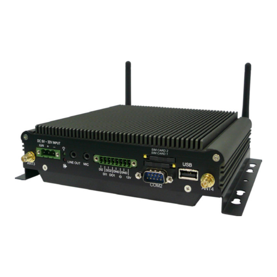
2 System Installation 2.1 System Introduction SIM Card2 DC In Power LED SIM Card1 Mic In Digital I/O USB2.0 Port Line Out GPS Antenna 3 3G Antenna 4 COM2 Port HDD/SSD LED LAN Port USB2.0 Port COM1 Port WIFI / BT Antenna 2 WIFI/BT Antenna 1... -
Page 39: Opening Chassis
2.2 Opening Chassis Step 1. Unscrew the four screws of the Back Cover as shown in the picture. Step 2. Unscrew the four screws of Rear/Front Panel as shown in the picture. Step 3. Open the Back Cover as shown in the picture. -
Page 40: Installing Memory
2.3 Installing Memory Step 1. Put Memory on this place as shown in the picture. Step 2. Hold the Memory with its notch aligned with the Memory socket of the board and insert it at a 30-degree angle into the socket as shown in the picture. -
Page 41: Installing Hdd / Ssd
2.4 Installing HDD / SSD Step 1. Put the HDD on the Back Cover as shown in the picture. Step 2. Turn over the Back Cover and screw the four screws of the Back Cover as shown in the picture. -
Page 42: Installing Mini Pci Express Expansion Card
2.5 Installing MINI PCI Express Expansion Card Step 1. Put MINI PCIe Expansion Card on this place as shown in the picture. Step 2. Hold the Module with its notch aligned with the socket of the board and insert it at a 30 degree angle into the socket as shown in the picture. -
Page 43: Installing Mini Pci Express Expansion Card
2.6 Installing MINI PCI Express Expansion Card Step 1. Put MINI PCIe Expansion Card on this place as shown in the picture. Step 2. Hold the Module with its notch aligned with the socket of the board and insert it at a 30 degree angle into the socket as shown in the picture. -
Page 44: Installing Sim Card
Step 1. Use thin stick to push the button as shown in the picture. Step 2. Take the holder away from FleetPC-4-B as shown in the picture. Step 3. Put your SIM Card into the holder as shown in the picture. -
Page 45: Installing Battery Module
2.8 Installing Battery Module Step 1. Screw two screws on the back cover as shown in the picture. Step 2. Connect the Cable to UPS1 Connector as shown in the picture. -
Page 46: Bios
• Upon boot-up, the 1st line appearing after the memory count is the BIOS version. It is usually in the format. FleetPC-4-B Mainboard V1.0 073109 where : 1st digit refers to BIOS maker as A = AMI, W = AWARD, and P = PHOENIX 2nd - 5th digit refers to the model number. - Page 47 Control Keys Power on the computer and the system will start POST (Power On Self Test) process. When the message below appears on the screen, press (DEL) key to enter Setup. <↑> Move to the previous item <↓> Move to the next item <←>...
-
Page 48: Main
3.2 Main System Time This setting allows you to set the system time. The time format is <Hour> <Minute> <Second>. System Date This setting allows you to set the system Date. The time format is <Day> <Month> <Date> <Year>. -
Page 49: Advanced
3.3 Advanced CPU Configuration ... - Page 50 » Max CPUID Value Limit The Max CPUID Value Limit BIOS feature allows you to circumvent problems with older operating systems that do not support the Intel Pentium 4 processor with Hyper-Threading Technology. When enabled, the processor will limit the maximum CPUID input value to 03h when queried, even if the processor supports a higher CPUID input value.
- Page 51 PCI/ PCIE Device Configuration ...
- Page 52 Super IO Configuration » Serial Port 0/1/2/3/4/5 Enable or Disable Select an Enable or Disable for the specified serial ports. » Serial Port 0 Mode The settings specify the RS-232/RS-422/RS-485 mode of the serial prot 0.
- Page 53 Hardware Health Configuration These items display the current status of all monitored hardware devices/components such as voltages, temperatures and all fans' speeds.
- Page 54 GPIO Configuration » GPO 0/ 1/ 2/ 3/ Data These settings configure special GPIO data. Power off Delay Time Setting ...
-
Page 55: Boot
3.4 Boot » 1st/2nd/3rd Boot Device The items allow you to set the sequence of boot devices where BIOS attempts to load the disk operating system. » Try Other Boot Devices Setting the option to [Enabled] allows the system to try to boot from other device if the system fail to boot from the 1st/2nd/3rd boot device. -
Page 56: Security
3.5 Security » Administrator Password Administrator Password controls access to the BIOS Setup utility. These settings allow you to set or change the administrator password. » User Password User Password controls access to the system at boot. These settings allow you to set or change the user password. -
Page 57: Chipset
3.6 Chipset... - Page 58 » Select Graphic Output Mode...
-
Page 59: Exit
3.7 Exit » Save Changes and Exit Save changes to CMOS and exit the Setup Utility. » Discard Changes and EXit Abandon all changes and exit the Setup Utility. » Discard Changes Abandon all changes and continue with the Setup Utility. »... -
Page 60: Packing List
4 Packing List 4.1 Packing List Part Number Module Name 763110011004 FleetPC-4-B 326710039661 CABLING PHOENIX CON MALE 3PIN 324610088661 CABLING PHOENIX CON MALE 8PIN Option 514001105200 Memory 1GB SO-DIMM DDR3 1333 514002105200 Memory 2GB SO-DIMM DDR3 1333 514004105200 Memory 4GB SO-DIMM DDR3 1333 521340012200 HDD WD 160GB SATA HDD / 5400/8MB/12ms , 9.5mm... - Page 61 Part Number Module Name Embedded u-blox6 GPS with Dead Reckoning Mini PCIe Card •50-channel u-blox6 Engine with Over 2 Million Effective Correlators •-146dBm SuperSense® Acquisition and Tracking Sensitivity •AssistNow Online and Offline A-GPS Services,OMA SUPL Compliant 570800100101 •100% Coverage with Continuous Position Fixes Even in Tunnels •Highly Accurate and Reliable Navigation Performance •Automatic Sensor Calibration and Temperature •Operating Temperature : -40ºC to 85ºC...
Need help?
Do you have a question about the FleetPC-4-B and is the answer not in the manual?
Questions and answers