Table of Contents
Advertisement
Quick Links
FleetPC-5-B
In-Vehicle Computing
User's Manual
Document Name
FleetPC-5-B User Manual
Version
1.0
Reversion History :
Reversion
From
To
1.0
1.0
Jane 1 , 2018
All manuals and user guides at all-guides.com
Version 1.0
Date
Initial document issued
Document No.
Date
Notes
UM2018321010
June 1, 2018
Author(s)
Stanley Chou
Advertisement
Table of Contents

Related Manuals for Cartft FleetPC-5-B


Summary of Contents for Cartft FleetPC-5-B
- Page 1 All manuals and user guides at all-guides.com FleetPC-5-B In-Vehicle Computing User's Manual Version 1.0 Document Name FleetPC-5-B User Manual Document No. UM2018321010 Version Date June 1, 2018 Reversion History : Reversion Date Notes Author(s) From Jane 1 , 2018 Initial document issued...
- Page 2 into any language, or transmitted in any form or by any means such as electronic, mechanical, magnetic, optical, chemical, photocopy, manual, or otherwise, without prior written permission from CarTFT.com e.K. Other brands and product names used herein are for identification purposes only and may be trademarks of their respective owners. Disclaimer CarTFT.com e.K. shall not be liable for any incidental or consequential damages resulting from the performance or use of this product. CarTFT.com e.K. makes no representation or warranty regarding the content of this manual. Information in this manual had been carefully checked for accuracy; however, no guarantee is given as to the correctness of the contents. For continuing product improvement, CarTFT.com e.K. reserves the right to revise the manual or make changes to the specifications of this product at any time without notice and obligation to any person or entity regarding such change. The information contained in this manual is provided for general use by customers. This device complies to Part 15 of the FCC Rules. Operation is subject to the following two conditions:...
- Page 3 All manuals and user guides at all-guides.com Safety Information Read the following precautions before setting up a CarTFT.com Product. Electrical safety To prevent electrical shock hazard, disconnect the power cable from the electrical outlet before relocating the system. When adding or removing devices to or from the system, ensure that the power cables for the devices are unplugged before the signal cables are connected. If possible, disconnect all power cables from the existing system before you add a device.
- Page 4 Incorrectly replacing the battery may damage this computer. Replace only with the same or its equivalent as recommended by CarTFT.com e.K. Dispose used battery according to the manufacturer's instructions.
-
Page 5: Table Of Contents
All manuals and user guides at all-guides.com 1.0 Introduction TABLE OF CONTENTS Page # 1.0Introduction................................8 1.1 Model Specification............................8 1.2 VBOX-3210 Illustration (MB, System)......................9 1.3 Architecture..............................13 1.4 Power Consumption.............................13 2.0Internal Connector Specification........................15 2.1 Battery Connector (BAT1)...........................15 2.2 COM Port Connector (COM1)........................16 2.3 COM Port Connector (COM2)........................17 2.4 COM Port Connector (COM3)........................18 2.5 COM Port Connector (COM4)........................19 2.6 MCU DOWN Connector..........................20... - Page 6 All manuals and user guides at all-guides.com 1.0 Introduction 3.5 LAN Connector (LAN1)..........................43 3.6 LAN Connector (LAN2)..........................44 3.7 LAN + USB 3.0 Connector...........................45 3.8 DIO Connector..............................46 3.9 AUDIO Connector............................47 4.0System Installation..............................50 4.1 System Introduction.............................50 4.2 Opening Chassis............................51 4.3 Installing Memory............................53 4.4 Installing MINI PCIe Expansion Card (Minicard 1, 3G/LTE)..............55 4.5 Installing MINI PCIe Expansion Card (MiniCard 2)................57 4.6 Installing MINI PCIe Expansion Card (MiniCard 3)................59...
- Page 7 All manuals and user guides at all-guides.com 1.0 Introduction INTRODUCTION User’s Manual...
-
Page 8: Introduction
All manuals and user guides at all-guides.com 1.0 Introduction INTRODUCTION Model Specification System AMD RX‐421BD Quad Core 2.1GHz up to 3.4 GHz* AMD RX‐216GD Dual Core 1.6GHz up to 3.0 GHz (Optional GX‐224IJ, GX‐215JJ) *Config to 15W Memory 2 x SO‐DIMM DDR4 up to 32GB (1 x SO‐DIMM DDR4 for GX series) Graphics AMD Radeon™ graphics 2 x Serial ATA GEN 3.0 LAN Chipset 2 x Intel i210‐AT; Ethernet Swtich: 1 x Marvell 88E6176 Watchdog 1 ~ 255 Level Reset Power Requirement Power Input 9V‐48V DC Power input Power Protection Automatics Recovery Short Circuit Protection Power Management Vehicle Power Ignition for Variety Vehicle Power Off Control Power off Delay Time Setting by BIOS and Software Internal Battery Kit for 10 Mins Operating (Optional) Battery Patent No. : M447854 ‐ Build‐in Battery Storage User’s Manual Page... -
Page 9: Vbox-3210 Illustration (Mb, System)
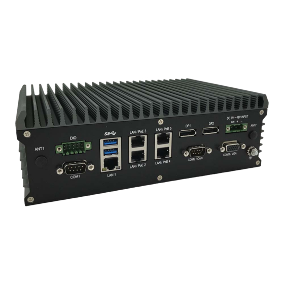
All manuals and user guides at all-guides.com 1.0 Introduction 1 x 2.5" Drive Bay for SATA Type HDD/SSD Type 1 x Cfast slot Qualification Certifications CE, FCC Class A, E13 Serial Port 2 x RS232/422/485 (option additional 2 x RS232) USB Port 2 x USB 3.0 ports and 2 x USB2.0 Ports 5 x RJ45 Ports GbE (Optinal for 4 x POE 802.3at/af*) Video Port 2 x DP (Option additional 1 x VGA for RX series) GPIO Port 4 In and 4 Out Audio Mic‐in/Line‐out(Optional Line in) 3 x Mini‐card slots Expansion Bus 1 x M.2 A‐E key 2230 slot Antenna Antenna 4 x SMA‐type External Antenna Connectors SIM Card Socket SIM Card Socket 2 x SIM Card Sockets Supported Onboard with eject Environment Operating Temp. ‐40ºC ~ 70ºC (w/SSD) Storage Temp. ‐40ºC ~ 85ºC Relative Humidity 5% RH – 95% RH Vibration (random) IEC60068‐2‐64, random, 2.5G@5~500Hz, 1hr/axis with SSD Vibration Operating... - Page 10 All manuals and user guides at all-guides.com 1.0 Introduction Front I/O User’s Manual Page...
- Page 11 All manuals and user guides at all-guides.com 1.0 Introduction Rear I/O System User’s Manual Page...
- Page 12 All manuals and user guides at all-guides.com 1.0 Introduction User’s Manual Page...
-
Page 13: Architecture
All manuals and user guides at all-guides.com 1.0 Introduction Architecture DUAL‐CH Intel MDI BUS PCI‐E X1 #0 RJ45 Type1 Dual Channel SO‐DIMM DDR4 2400 MHz WGI210AT DDR4 BUS PORT 1 Type3 Single Channel (CH‐B) max: 16GB PoE is optional MDI BUS RJ45 PORT 2 (PoE) MDI BUS Display Port 1 Intel PCI‐E X1 #1 WGI210AT Type1 Support DP0,1,2 MDI BUS RJ45 R series ‐ SOC Ethernet Switch PORT 3 (PoE) Type3 Support DP0,1 Display Port 2 Marvell 88E6176 Merlin Falcon (FP4) MDI BUS RJ45... - Page 14 All manuals and user guides at all-guides.com 2.0 Internal Connector Specification INTERNAL CONNECTOR SPECIFICATION User’s Manual...
-
Page 15: Internal Connector Specification
All manuals and user guides at all-guides.com 2.0 Internal Connector Specification INTERNAL CONNECTOR SPECIFICATION Battery Connector (BAT1) User’s Manual Page... -
Page 16: Com Port Connector (Com1)
All manuals and user guides at all-guides.com 2.0 Internal Connector Specification COM Port Connector (COM1) Connector size 2 X 5 = 10 Pin Connector type JST-2.0mm-M-180 Connector location COM1 Connector pin Signal Signal definition COM1_DCD COM1_RXD COM1_TXD COM1_DTR COM1_DSR COM1_RTS COM1_CTS COM1_RI DB9 pin definition Signal RS232 RS422... -
Page 17: Com Port Connector (Com2)
All manuals and user guides at all-guides.com 2.0 Internal Connector Specification COM Port Connector (COM2) Connector size 2 X 5 = 10 Pin Connector type JST-2.0mm-M-180 Connector location COM2 Connector pin Signal Signal definition COM2_DCD COM2_RXD COM2_TXD COM2_DTR COM2_DSR COM2_RTS COM2_CTS COM2_RI DB9 pin definition Signal RS232 RS422... -
Page 18: Com Port Connector (Com3)
All manuals and user guides at all-guides.com 2.0 Internal Connector Specification COM Port Connector (COM3) Connector size 2 X 5 = 10 Pin Connector type JST-2.0mm-M-180 Connector location COM3 Connector pin Signal Signal definition COM3_DCD COM3_RXD COM3_TXD COM3_DTR COM3_DSR COM3_RTS COM3_CTS COM3_RI DB9 pin definition Signal RS232 RS422... -
Page 19: Com Port Connector (Com4)
All manuals and user guides at all-guides.com 2.0 Internal Connector Specification COM Port Connector (COM4) Connector size 2 X 5 = 10 Pin Connector type JST-2.0mm-M-180 Connector location COM4 Connector pin Signal Signal definition COM4_DCD COM4_RXD COM4_TXD COM4_DTR COM4_DSR COM4_RTS COM4_CTS COM4_RI DB9 pin definition Signal RS232 RS422... -
Page 20: Mcu Down Connector
All manuals and user guides at all-guides.com 2.0 Internal Connector Specification MCU DOWN Connector Connector size 1 X 4 = 4 Pin Connector type JST-2.0mm-M-180 Connector location MCU_DOWN1 Connector pin Signal definition MCU_PROGRAM User’s Manual Page... -
Page 21: Dip Switch Connector
All manuals and user guides at all-guides.com 2.0 Internal Connector Specification DIP Switch Connector Connector size DIP-Switch 2x2 PIN Connector type pitch=1.27mm Connector location Connector pin Default is set at ON definition Switch Description 1-2 ON SMBUS switched ON for MINICARD2 3-4 ON Switch Description User’s Manual... -
Page 22: Sata Power Connector
All manuals and user guides at all-guides.com 2.0 Internal Connector Specification SATA Power Connector Connector size 1 X 4 = 4 Pin Connector type WAFER 2.54mm-M-180 Connector location SATAPWR1 Connector pin Signal definition +12V User’s Manual Page... -
Page 23: Sata Connector
All manuals and user guides at all-guides.com 2.0 Internal Connector Specification Connector map SATA Connector Connector size 1 X 7 = 7 Pin Connector type SATA 1.27mm-M-180D Connector location SATA1 Connector pin Signal definition SATA_TXP0 SATA_TXN0 SATA_RXN0 SATA_RXP0 User’s Manual Page... -
Page 24: Usb Connector
All manuals and user guides at all-guides.com 2.0 Internal Connector Specification Connector map 2.10 USB Connector Connector size 2 X 4 = 8 Pin Connector type JST-2.0mm-M-180 Connector location USB2 Connector pin Signal Signal definition +5VDC +5VDC USB0_10N USB1_11N USB0_10P USB1_11P User’s Manual Page... -
Page 25: Debug Connector
All manuals and user guides at all-guides.com 2.0 Internal Connector Specification Connector map 2.11 DEBUG Connector Connector size 2 X 5 = 10 Pin Connector type JST-2.0mm-M-180 Connector location DEBUG1 Connector pin Signal Signal definition LCLK LAD1 LRST# LAD0 LFRAME# +3.3VDC LAD3 LAD2 User’s Manual... -
Page 26: Spi Connector
All manuals and user guides at all-guides.com 2.0 Internal Connector Specification Connector map 2.12 SPI Connector Connector size 2 X 5 = 10 Pin Connector type JST-2.0mm-M-180 Connector location SPI1 Connector pin Signal Signal definition SPI_HOLD# SPI_CS1# SPI_VCC SPI_MISO SPI_CLK SPI_MOSI User’s Manual Page... -
Page 27: Ups Connector
All manuals and user guides at all-guides.com 2.0 Internal Connector Specification Connector map 2.13 UPS Connector Connector size 1 X 5 = 5 Pin Connector type JST-2.0mm-M-180 Connector location UPS1 Connector pin Signal definition UPS_POWER UPS_POWER User’s Manual Page... -
Page 28: Vga Connector
All manuals and user guides at all-guides.com 2.0 Internal Connector Specification Connector map 2.14 VGA Connector Connector size 2 X 8 = 16 Pin Connector type JST-2.0mm-M-180 Connector location VGA1 Connector pin Signal Signal definition GREEN BLUE User’s Manual Page... -
Page 29: Mini Pci-E Connector (Minicard1)
All manuals and user guides at all-guides.com 2.0 Internal Connector Specification CRT_VCC DAC_SDATA HSYNC VSYNC DAC_SCLK Connector map 2.15 Mini PCI‐E Connector (MINICARD1) Connector size 2 X 26 = 52 Pin Connector type MINI PCI-E CON 9.2mmH Connector location MINICARD1 (Mini PCI-E spec. V1.2) Connector pin Signal Signal... - Page 30 All manuals and user guides at all-guides.com 2.0 Internal Connector Specification UIM_PWR_A UIM_DAT_A UIM_CLK_A UIM_RST_A MINICARD1_DIS# PCIE_RST# 3VSB USB_1N USB_1P 3VSB 3VSB LED_WWAN# 3VSB Connector map User’s Manual Page...
-
Page 31: Mini Pci-E Connector (Minicard2)
All manuals and user guides at all-guides.com 2.0 Internal Connector Specification 2.16 Mini PCI‐E Connector (MINICARD2) Connector size 2 X 26 = 52 Pin Connector type MINI PCI-E CON 9.2mmH Connector location MINICARD2 (Mini PCI-E spec. V1.2) Connector pin Signal Signal definition PCIE_WAKE# 3VSB +1.5V MINICARD2_CLKREQ#... - Page 32 All manuals and user guides at all-guides.com 2.0 Internal Connector Specification 3VSB 3VSB +1.5V 3VSB Connector map User’s Manual Page...
-
Page 33: Mini Pci-E Connector (Minicard3)
All manuals and user guides at all-guides.com 2.0 Internal Connector Specification 2.17 Mini PCI‐E Connector (MINICARD3) Connector size 2 X 26 = 52 Pin Connector type MINI PCI-E CON 9.2mmH Connector location MINICARD3 (Mini PCI-E spec. V1.2) Connector pin Signal Signal definition PCIE_WAKE# 3VSB +1.5V MINICARD3_CLKREQ#... - Page 34 All manuals and user guides at all-guides.com 2.0 Internal Connector Specification Connector map User’s Manual Page...
-
Page 35: Connector
All manuals and user guides at all-guides.com 2.0 Internal Connector Specification 2.18 M.2 Connector Connector size 75 Pin Connector type NGFF CON 8.5mmH Connector location NGFF1 (A-E Key) Connector pin Signal Signal definition 3VSB USB0P 3VSB USB0N MODULE KEY MODULE KEY MODULE KEY MODULE KEY MODULE KEY... - Page 36 All manuals and user guides at all-guides.com 2.0 Internal Connector Specification Connector map User’s Manual Page...
-
Page 37: Cfast Connector
All manuals and user guides at all-guides.com 2.0 Internal Connector Specification 2.19 CFAST Connector Connector size 24 Pin Connector type CFAST 90D Connector location CFAST1 Connector pin Signal Signal definition SATA_TXP1 SATA_TXN1 SATA_RXN1 SATA_RXP1 +3.3VDC +3.3VDC Connector map User’s Manual Page... - Page 38 All manuals and user guides at all-guides.com 3.0 External Connector Specification EXTERNAL CONNECTOR SPECIFICATION User’s Manual...
-
Page 39: External Connector Specification
All manuals and user guides at all-guides.com 3.0 External Connector Specification EXTERNAL CONNECTOR SPECIFICATION Power Input Connector Connector size 1 X 3 = 3 Pin Connector type Terminal block 3PIN pitch :5.08mm Connector location PWR1 Connector pin definition Signal VIN (9VDC~48VDC) IGNITION Connector map User’s Manual Page... -
Page 40: Dp Connector (Dp1)
All manuals and user guides at all-guides.com 3.0 External Connector Specification DP Connector (DP1) Connector size 20 Pin Connector type Display port Connector location Connector pin definition Signal Signal DP1_LANE_0P DP1_LANE_0N DP1_LANE_1P DP1_LANE_1N DP1_LANE_2P DP1_LANE_2N DP1_LANE_3P DP1_LANE_3N DP1_AUX_EN# DP1_AUXP_CLK DP1_AUXN_DATA DP1_HPD DP1_VCC3 Connector map User’s Manual Page... -
Page 41: Dp Connector (Dp2)
All manuals and user guides at all-guides.com 3.0 External Connector Specification DP Connector (DP2) Connector size 20 Pin Connector type Display port Connector location Connector pin definition Signal Signal DP2_LANE_0P DP2_LANE_0N DP2_LANE_1P DP2_LANE_1N DP2_LANE_2P DP2_LANE_2N DP2_LANE_3P DP2_LANE_3N DP2_AUX_EN# DP2_AUXP_CLK DP2_AUXN_DATA DP2_HPD DP2_VCC3 Connector map User’s Manual Page... -
Page 42: Usb Connector
All manuals and user guides at all-guides.com 3.0 External Connector Specification USB Connector Connector size 8 Pin Connector type USB2.0 Type A Connector location USB1 Connector pin definition Signal Signal 5VSB USB8_N USB8_P 5VSB USB9_N USB9_P Connector map User’s Manual Page... -
Page 43: Lan Connector (Lan1)
All manuals and user guides at all-guides.com 3.0 External Connector Specification LAN Connector (LAN1) Connector size 32 Pin Connector type RJ45+LED Connector location LAN1 Connector pin definition PoE/LAN2 Signal Signal LAN2_MDI0P LAN2_MDI0N LAN2_MDI1P LAN2_MDI2P LAN2_MDI2N LAN2_MDI1N LAN2_MDI3P LAN2_MDI3N PoE/LAN3 Signal Signal LAN3_MDI0P LAN3_MDI0N LAN3_MDI1P LAN3_MDI2P... -
Page 44: Lan Connector (Lan2)
All manuals and user guides at all-guides.com 3.0 External Connector Specification Connector map LAN Connector (LAN2) Connector size 32 Pin Connector type RJ45+LED Connector location LAN2 Connector pin definition PoE/LAN4 Signal Signal LAN4_MDI0P LAN4_MDI0N LAN4_MDI1P LAN4_MDI2P LAN4_MDI2N LAN4_MDI1N LAN4_MDI3P LAN4_MDI3N PoE/LAN5 Signal Signal LAN5_MDI0P LAN5_MDI0N... -
Page 45: Lan + Usb 3.0 Connector
All manuals and user guides at all-guides.com 3.0 External Connector Specification LAN5_MDI3P LAN5_MDI3N Connector map LAN + USB 3.0 Connector Connector size 28 Pin Connector type RJ45+LED+USB3.0 Connector location RJ45_USB1 Connector pin LAN1 definition Signal Signal LAN1_MDI0P LAN1_MDI0N LAN1_MDI1P LAN1_MDI2P LAN1_MDI2N LAN1_MDI1N LAN1_MDI3P LAN1_MDI3N USB LOWER Signal Signal... -
Page 46: Dio Connector
All manuals and user guides at all-guides.com 3.0 External Connector Specification USB4_OP USB_SS_RXN0 USB_SS_RXP0 USB_SS_TXN0 USB_SS_TXP0 Connector map DIO Connector Connector size 2x5=10PIN(Male) pitch:3.5mm Connector type 90D Terminal Block Connector location DIO1 Connector pin definition Signal Signal DO_1 DI_1 DO_2 DI_2 DO_3 DI_3 DO_4... -
Page 47: Audio Connector
All manuals and user guides at all-guides.com 3.0 External Connector Specification Connector map AUDIO Connector Connector size 34 Pin Connector type AUDIO PHONE JACK Connector location AUDIO1 Connector pin definition Signal MIC_OUT_R MIC_JD MIC_OUT_L FRONT_OUT_R FRONT_JD FRONT_OUT_L User’s Manual Page... - Page 48 All manuals and user guides at all-guides.com 3.0 External Connector Specification LINE_IN_R LINE_IN_JD LINE_IN_L Connector map User’s Manual Page...
- Page 49 All manuals and user guides at all-guides.com 4.0 System Installation SYSTEM INSTALLATION User’s Manual...
-
Page 50: System Installation
All manuals and user guides at all-guides.com 4.0 System Installation SYSTEM INSTALLATION System Introduction User’s Manual Page... -
Page 51: Opening Chassis
All manuals and user guides at all-guides.com 4.0 System Installation Opening Chassis Step1. Unscrew the six screws of the Back Cover as shown in the picture. Step2. Unscrew the three screws of the Front Panel as shown in the picture. User’s Manual Page... - Page 52 All manuals and user guides at all-guides.com 4.0 System Installation Step3. Unscrew the three screws of the Rear Panel as shown in the picture. Step4. Open Bottom Cover as shown in the picture. User’s Manual Page...
-
Page 53: Installing Memory
All manuals and user guides at all-guides.com 4.0 System Installation Installing Memory Step1. Put Memory on this place as shown in the picture. Step2. Hold the Memory with its notch aligned with the Memory socket of the board and insert it at a 30‐degree angle into the socket as shown in the picture. User’s Manual Page... - Page 54 All manuals and user guides at all-guides.com 4.0 System Installation Step3. Press down on the Memory so that the tabs of the socket lock on both sides of the module as shown in the picture. User’s Manual Page...
-
Page 55: Installing Mini Pcie Expansion Card (Minicard 1, 3G/Lte)
All manuals and user guides at all-guides.com 4.0 System Installation Installing MINI PCIe Expansion Card (Minicard 1, 3G/LTE) Step 1. Put MINI PCIe Expansion Card on this place as shown in the picture. Step 2. Hold the Module with its notch aligned with the socket of the board and insert it at a 30 degree angle into the socket as shown in the picture. User’s Manual Page... - Page 56 All manuals and user guides at all-guides.com 4.0 System Installation Step 3. Screw one screw to the holder as shown in the picture. Step 4. Done as shown in the picture. User’s Manual Page...
-
Page 57: Installing Mini Pcie Expansion Card (Minicard 2)
All manuals and user guides at all-guides.com 4.0 System Installation Installing MINI PCIe Expansion Card (MiniCard 2) Step 1. Put MINI PCIe Expansion Card on this place as shown in the picture. Step 2. Hold the Module with its notch aligned with the socket of the board and insert it at a 30 degree angle into the socket as shown in the picture. User’s Manual Page... - Page 58 All manuals and user guides at all-guides.com 4.0 System Installation Step 3. Screw one screw to the holder as shown in the picture. Step 4. Done as shown in the picture. User’s Manual Page...
-
Page 59: Installing Mini Pcie Expansion Card (Minicard 3)
All manuals and user guides at all-guides.com 4.0 System Installation Installing MINI PCIe Expansion Card (MiniCard 3) Step 1. Put MINI PCIe Expansion Card on this place as shown in the picture. Step 2. Hold the Module with its notch aligned with the socket of the board and insert it at a 30 degree angle into the socket as shown in the picture. User’s Manual Page... - Page 60 All manuals and user guides at all-guides.com 4.0 System Installation Step 3. Screw one screw to the holder as shown in the picture. Step 4. Done as shown in the picture. User’s Manual Page...
-
Page 61: Installing M.2 Module
All manuals and user guides at all-guides.com 4.0 System Installation Installing M.2 Module Step 1. Put M.2 Card on this place as shown in the picture. Step 2. Hold the Module with its notch aligned with the socket of the board and insert it at a 30 degree angle into the socket as shown in the picture. User’s Manual Page... - Page 62 All manuals and user guides at all-guides.com 4.0 System Installation Step 3. Screw one screw to the holder as shown in the picture. Step 4. Done as shown in the picture. User’s Manual Page...
-
Page 63: Installing Internal Antenna Cable
All manuals and user guides at all-guides.com 4.0 System Installation Installing Internal Antenna Cable Step 1. Take the SMA Connector and Plug into IO Panel as shown in the picture. Step 2. Put the Washer into the SMA Connector as shown in the picture. User’s Manual Page... - Page 64 All manuals and user guides at all-guides.com 4.0 System Installation Step 3. Put the Oring to SMA Connector and tighten as shown in the picture. Step 4. Done as shown in the picture. User’s Manual Page...
- Page 65 All manuals and user guides at all-guides.com 4.0 System Installation Step 5. Take the Ipex Connector and press on the 3G/LTE module as shown in the picture. Step 6. Take the Ipex Connector and press on the GPS module as shown in the picture. User’s Manual Page...
- Page 66 All manuals and user guides at all-guides.com 4.0 System Installation Step 7. Take the Ipex Connector and press on the wifi module as shown in the picture. Step 8. Take the Ipex Connector and press on the M.2 module as shown in the picture. User’s Manual Page...
-
Page 67: Installing Sim Card
All manuals and user guides at all-guides.com 4.0 System Installation Installing SIM Card Step 1. Use thin stick to push the button as shown in the picture. Step 2. Take the holder away from front panel as shown in the picture. User’s Manual Page... - Page 68 All manuals and user guides at all-guides.com 4.0 System Installation Step 3. Put your SIM Card into the holder and take the SIM card holder and Insert it into the socket as shown in the picture. Attention: When insert a SIM card to the SIM card holder, please remove the main power at input to avoid undetectable SIM card. User’s Manual Page...
-
Page 69: Installing Hdd
All manuals and user guides at all-guides.com 4.0 System Installation 4.10 Installing HDD Step 1. Put the HDD into HDD Holder as shown in the picture. Step 2. Screw two screws on both side as shown in the picture. User’s Manual Page... - Page 70 All manuals and user guides at all-guides.com 4.0 System Installation Step 3. Push the HDD Holder into the socket as shown in the picture. Step 4. Fully insert the HDD Holder into the socket until a “click” is heard as shown in the picture. User’s Manual Page...
- Page 71 All manuals and user guides at all-guides.com 4.0 System Installation Step 5. Tighten to Storage Bracket screws as shown in the picture. User’s Manual Page...
-
Page 72: Installing Cfast Card Module
All manuals and user guides at all-guides.com 4.0 System Installation 4.11 Installing CFast Card Module Step 1. Put CFast Card on this place as shown in the picture. Step2. Unscrew the three screws of the Front Panel as shown in the picture. User’s Manual Page... - Page 73 All manuals and user guides at all-guides.com 4.0 System Installation Step 3. Take CFast Card into the holder as shown in the picture. Step 4. Fully insert the CFast Card into the socket until a “click” is heard as shown in the picture. User’s Manual Page...
- Page 74 All manuals and user guides at all-guides.com 4.0 System Installation Step 5. Put the Front Panel back and screw the three screws of it as shown in the picture. Unscrew the three screws of the Front Panel as shown in the picture. Step 5. Done as shown in the picture. User’s Manual Page...
-
Page 75: Installing Poe Module
All manuals and user guides at all-guides.com 4.0 System Installation 4.12 Installing POE Module Step 1. Put POE Module on this place as shown in the picture. Step 4. Put the POE‐8P module on the motherboard as shown in the picture User’s Manual Page... - Page 76 All manuals and user guides at all-guides.com 4.0 System Installation Step 5. Screw the three screws as shown in the picture Step 6. Done as shown in the picture User’s Manual Page...
- Page 77 All manuals and user guides at all-guides.com 5.0 BIOS BIOS User’s Manual...
-
Page 78: Bios
All manuals and user guides at all-guides.com 5.0 BIOS BIOS Enter The BIOS Power on the computer and the system will start POST (Power On Self Test) process. When the message below appears on the screen, press (DEL) key to enter Setup. Press DEL to enter SETUP If the message disappears before you respond and you still wish to enter Setup, restart the system by turning it OFF and On or pressing the RESET button. You may also restart the system by simultaneously pressing <Ctrl>, <Alt>, and <Delete> keys. Important The items under each BIOS category described in this chapter are under continuous update for better system performance. Therefore, the description may be slightly different from the latest BIOS and should be held for reference only. Upon boot‐up, the 1st line appearing after the memory count is the BIOS version. It is usually in the format. ABOX‐5000(P)G1 Mainboard V1.0 073109 where : 1st digit refers to BIOS maker as A = AMI, W = AWARD, and P = PHOENIX 2nd ‐ 5th digit refers to the model number. 6th digit refers to the chipset as I = Intel, N = NVIDIA, A = AMD and V = VIA. 7th ‐ 8th digit refers to the customer as MS = all standard customers. V1.0 refers to the BIOS was released. 073109 refers to the date this BIOS was released. 78 78 User’s Manual Page... - Page 79 All manuals and user guides at all-guides.com 5.0 BIOS Control Keys Power on the computer and the system will start POST (Power On Self Test) process. When the message below appears on the screen, press (DEL) key to enter Setup. <↑> Move to the previous item <↓> Move to the next item <←> Move to the item in the left hand <→> Move to the item in the right hand <Enter> Select the item <Esc> Jumps to the Exit menu or returns to the main menu from a submenu <+/PU> Increase the numeric value or make changes <‐/PD> Decrease the numeric value or make changes <F1> General Help <F3> Load Optimized Defaults <F4> Save all the CMOS changes and exit Getting Help After entering the Setup menu, the first menu you will see is the Main Menu. Main Menu The main menu lists the setup functions you can make changes to. You can use the arrow keys (↑↓) to select the item. The on‐line descrip on of the highlighted setup function is displayed at the bottom of the screen.
-
Page 80: Main
All manuals and user guides at all-guides.com 5.0 BIOS Main Time Setting » System Date This setting allows you to set the system Date. The time format is <Day> <Month> <Date> <Year>. » System Time This setting allows you to set the system time. The time format is <Hour> <Minute> <Second>. 80 80 User’s Manual Page... -
Page 81: Advanced
All manuals and user guides at all-guides.com 5.0 BIOS Advanced AMT Configuration Serial Port Configuration 81 81 User’s Manual Page... - Page 82 All manuals and user guides at all-guides.com 5.0 BIOS » Serial Port 1/2/3/4 Enable or Disable Select an Enable or Disable for the specified serial ports. » COM1 RS232/422/485 Select 82 82 User’s Manual Page...
- Page 83 All manuals and user guides at all-guides.com 5.0 BIOS » Watch Dog Function 83 83 User’s Manual Page...
-
Page 84: Chipset
All manuals and user guides at all-guides.com 5.0 BIOS Chipset RAID Mode 84 84 User’s Manual Page... - Page 85 All manuals and user guides at all-guides.com 5.0 BIOS 85 85 User’s Manual Page...
-
Page 86: Boot
All manuals and user guides at all-guides.com 5.0 BIOS Boot » 1st/2nd Boot Device The items allow you to set the sequence of boot devices where BIOS attempts to load the disk operating system. » Try Other Boot Devices Setting the option to [Enabled] allows the system to try to boot from other device if the system fail to boot from the 1st/2nd boot device. » Hard Disk Drives, CD/DVD Drives, USB Drives These settings allow you to set the boot sequence of the specified devices. 86 86 User’s Manual Page... - Page 87 All manuals and user guides at all-guides.com 5.0 BIOS 87 87 User’s Manual Page...
- Page 88 All manuals and user guides at all-guides.com 6.0 Packing List PACKING LIST User’s Manual...
-
Page 89: Packing List
All manuals and user guides at all-guides.com 6.0 Packing List PACKING LIST Packing List System Item Part Number Module Name 763210020001 FleetPC‐5‐B‐G215 System 763210020002 FleetPC‐5‐BP‐G215 System 763210020003 FleetPC‐5‐B‐G224 System 763210020004 FleetPC‐5‐BP‐G224 System 763210020005 FleetPC‐5‐B‐R216 System 763210020006 FleetPC‐5‐BP‐R216 System 763210020007 FleetPC‐5‐B‐R421 System 763210020008 FleetPC‐5‐BP‐R421 System Accessory Picture Part Number Module Name Q’ty 326910039661 Cabling MC101‐508‐03G F 90D 326920087061 Cabling 2x5PIN(F) pitch:3.5mm 351102040110 Screw I Type M2*4L ISO NI... - Page 90 All manuals and user guides at all-guides.com 6.0 Packing List 351103060250 Screw F Type M3*6L ISO BK 351103060810 ROUND HAND SCREW W/SPRING_P3x0.5Px6L 370831501000 VBOX‐3150 Mount Bracket 417290370250 HDD‐RUBBER FOR H=7mm Silicone Rubber User’s Manual Page...
Need help?
Do you have a question about the FleetPC-5-B and is the answer not in the manual?
Questions and answers