Table of Contents
Advertisement
Quick Links
Advertisement
Table of Contents

Related Manuals for Cartft FLEETPC-4-F


Summary of Contents for Cartft FLEETPC-4-F
- Page 1 In-Vehicle Computing FleetPC-4-F User Manual V0.1 User Manual...
- Page 2 User Manual...
- Page 3 Other brands and product names used herein are for identification purposes only and may be trademarks of their respective owners. Disclaimer CARTFT.COM shall not be liable for any incidental or consequential damages resulting from the performance or use of this product. CARTFT.COM makes no representation or warranty regarding the content of this manual. Information in this manual had been carefully checked for accuracy; however, no guarantee is given to the ...
- Page 4 Trademarks CARTFT.COM is a registered trademark of CARTFT.COM All the trademarks, registrations, and brands mentioned herein are used for identification purposes only and may be trademarks and registered trademarks of their respective owners. Safety Information Read the following precautions before setting up a CARTFT.COM Product. Electrical safety To prevent electrical shock hazards, disconnect the power cable from the electrical outlet before relocating the system. When adding or removing devices to or from the system, ensure that the power cables for the devices are unplugged before the signal cables are connected. If possible, disconnect all power cables from the existing system before adding a device. Before connecting or removing signal cables from the motherboard, ensure that all power cables are unplugged. Seek professional assistance before using an adapter or extension cord. These devices ...
- Page 5 Do not leave this product in an environment where the storage temperature may be below ‐30°C or above 85°C. To prevent damages, the product must be used in a controlled environment. CAUTION Incorrectly replacing the battery may damage this computer. Replace only with the same or equivalent as recommended by CARTFT.COM Dispose of used battery according to the manufacturer's instructions. Technical Support Please do not hesitate to call or e‐mail our customer service when you cannot fix ...
-
Page 6: Table Of Contents
TABLE OF CONTENTS 1.0 PRODUCT INTRODUCTION ..................... 1 1 1.1 OVERVIEW ......................... 1 1 1.2 KEY FeatureS ........................ 1 1 1.3 Specification ........................ 1 2 1.4 Package Contents ...................... 1 5 1.5 Ordering Information ...................... 1 5 1.6 Optional Accessory ...................... 1 6 2.0 SYSTEM I/O ........................ 1 9 2.1 ... - Page 7 2.2.4 DC Input Terminal Block .................. 2 4 2.3 Illustration ...................... 2 6 2.3.1 System ...................... 2 6 2.3.2 Main Board ...................... 2 8 2.4 I/O Connector Definition ................. 2 9 2.4.1 Audio Connector .................... 2 9 2.4.2 LAN Connector .................... 2 9 2.4.3 USB 3.0_1/2 Connector ................... 2 9 2.4.4 USB 2.0_1/2 Connector ................... 2 9 2.4.5 ...
- Page 8 2.5.7 BAT Connector .................... 3 6 2.5.8 DIO JST connector .................... 3 7 2.5.9 COM JST Connector (RS‐232/422/485) .. 3 7 (Optional for model FLEETPC‐4‐F‐2S) 2.5.10 Remote BTN connector (OPTIONAL) ............... 3 7 3.0 SYSTEM SETUP ...................... 4 0 3.1 Opening the Chassis ...................... 4 0 3.2 Installing Memory ...................... 4 2 3.3 Installing Mini PCIe Expansion Card (PCIe/SATA/USB2.0) .......... 4 3 3.3 ...
- Page 9 5.4.1 PCH‐IO Express Configuration ................ 6 54 5.4.2 SATA ....................... 6 65 5.4.3 Graphics Configuration .................. 6 99 5.4.4 System Agent (SA) Configuration .............. 7 22 5.5 Boot .......................... 7 34 5.6 Save & Exit ......................... 6 4 User Manual...
-
Page 10: Product Introduction
Chapter 1 Product Introduction User Manual... - Page 11 User Manual...
-
Page 12: Overview
Furthermore, it features Smarter Vehicle Power Ignition and wireless remote control in various vehicles. FLEETPC‐4‐F can effectively support cars in extreme weather and operating conditions, such as Snowplow, Trucks, Buses, Taxis, and Forklifts. Combining Intel Braswell N3060 CPU, 5G, LTE, Wi‐Fi, Bluetooth wireless connectivity, and ultra‐compact enclosure, CarTFT.com' FLEETPC‐4‐F is a compact yet versatile In‐vehicle computer that can fuel various transportation systems. 1.2 KEY FEATURES ... -
Page 13: Specification
Battery backup (Optional) 1.3 SPECIFICATION System CPU Intel N3060 Dual‐Core CPU up to 2.48GHz Chipset N/A Memory 1 x DDR3L‐1600 SO‐DIMM up to 8GB Graphic Intel HD Graphics Lan Chipset 1 x Intel i210AT Gigabit Ethernet Watchdog 1 ~ 255 Level Reset TPM 2.0 I/O 2 x 3.2 Gen 1x1 USB Port 2 x USB 2.0 LAN 1 x RJ45 Ports for GbE 1 x HDMI Video Port 1 x DVI‐D *Use only with Single Link DVI Cables 2 x Analog Input (9~60V) DIO Port 4 x DI (5V~60V) 4 x DO (5V/100mA/port) Audio 1 x Mic‐in, 1 x Line‐out 1 x M.2 3042/3052 B Key for LTE/5G module Expansion Bus 1 x M.2 2230 A‐E Key for Wi‐Fi + Bluetooth 1 x mini PCIe slot support (USB + PCIe bus or mSATA) ... - Page 14 1 x M.2 2280 M key support SATA Bus *Additional heat sink is required. Please contact a sales representative for more Type information on a suitable model. Operating System Windows Windows 10 Linux Ubuntu 16.04 Environment Operating Temp. ‐30 ~ 60ºC, ambient w/ 0.6m/s airflow Storage Temp. ‐30 ~ 85ºC Relative Humidity 10% RH ~ 90% RH (non‐condensing) IEC60068‐2‐64, random, 2.5G@5~500Hz, 1hr/axis Vibration (with SSD) MIL‐STD‐810G, Method 514.6, Procedure I, Cat.4, Operating Operating: MIL‐STD‐810G, Method 516.6, Procedure I, Shock Trucks and semi‐trailers=15G (11ms) with M.2 SSD Certifications CE, FCC Class A, E13, ECE R118 Patent No. M447854 Build‐in Battery (Taiwan) Power Power Input 9 ~ 60 VDC Power Input ...
- Page 15 User Manual...
-
Page 16: Package Contents
1.4 PACKAGE CONTENTS Your product package should include the items listed below. If any of the items below is missing, contact the distributor or dealer from whom you purchased the product. Item Description Function Q’ty Terminal block for DC power input 326910039661 CABLING MC101‐508‐03G F 90D 1 connector 351102050110 Screw I Type M2*5L ISO For fastening miniPCIe modules 2 372800000900 M.2 Data Storage Heatsink Type_3 Heatsink for DRAM and M.2 Modem 1 Thermal pad for sticking on (372800000900) 265066022010 Thermal PAD 66x22x1.75T mm 1 heat sink for DRAM Thermal pad for sticking on the side of 1 265016037010 Thermal PAD 16x37x1.0T mm (372800000900) heat sink 351103060810 ROUND HAND SCREW W/SPRING_ P3x6L For fastening (372800000900), heat sink 1 351125100110 Screw I Type M2.5x10L For fastening (372800000900), heat sink 2 351125050110 Screw I Type M2.5x5L ... -
Page 17: Optional Accessory
1.6 OPTIONAL ACCESSORY CARTFT.COM provides optional accessories as follows. Please get in touch with your dealer or us if you need any. Item Order No. Description DRAM 515002107610 2GB DDR3L WT InnoDisk M3S0‐2GMJCDPC DRAM 515004107202 4GB DDR3L WT InnoDisk M3S0‐4GMSCDPC DRAM 515008107610 8GB DDR3L WT InnoDisk M3S0‐8GMSDDPC DRAM 510500210711 2GB DDR3L WT Apacer 75.A83E2.G030B DRAM 510500810710 8GB DDR3L WT Apacer 75.C93E2.G040B M.2 SSD 525006400020 64GB, ‐40~85°C, with DRAM IM2S3338‐064GP M.2 SSD 525012800020 128GB ‐40~85°C, with DRAM IM2S3338‐128GP M.2 SSD 525025600020 256GB ‐40~85°C, with DRAM IM2S3338‐256GP M.2 SSD 525051200020 512GB ‐40~85°C, with DRAM IM2S3338‐512GP M.2 SSD 525100000020 1TB ‐40~85°C, with DRAM IM2S3338‐1TP 5G 570010042001 5G SIM8202G M.2 Card‐SIMCom ... - Page 18 Chapter 2 I/O and Connectors User Manual...
- Page 19 User Manual...
-
Page 20: System I
2.0 SYSTEM I/O 2.1 FRONT PANEL INFORMATION 2.1.1 POWER BUTTON RED Light: Standby BLUE Light: Power On 2.1.2 LED INDICATORS ACC System Status Flash: Detection ON: System on Continue: Ignition Ready OFF: System off HDD UPS Flash: One of Storage Read/Write ON: UPS enables User Manual... -
Page 21: Sim Cards
2.1.3 SIM CARDS Support SIM Card size: Mini‐SIM. SIM Card is switchable, but the default setting is on SIM CARD1. Please contact your CARTFT.COM’ sales representative to get the utility or software control for the SIM card switch function. 2.1.4 USB CONNECTORS 2 x USB 2.0 2 x USB 3.2 Gen 1x1 User Manual... -
Page 22: Hdmi
2.1.5 H DMI Max Resolution: 3840 x 2160 @60Hz. 2.1.6 S ERIAL PORT (OPTIONAL FOR MODEL FLEETPC‐4‐F‐2S) 2 x RS 232/422/485 User Manual... -
Page 23: Dio
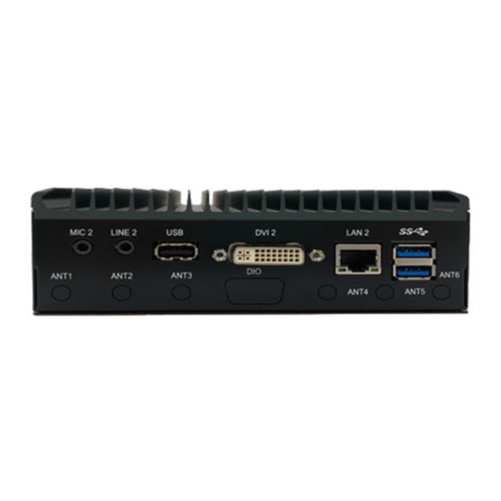
2.1.7 DIO 2 x Analog Input (9~60V, with 0.5V accuracy), 4 x DI (5V~60V), 4 x DO (5V/100mA/port) 2.2 REAR PANEL INFORMATION 2.2.1 AUDIO JACKS The system's audio function features high‐definition audio Realtek ALC888‐vD2‐ GR codec. There are two 3.5mm audio jacks for Mic‐in and Line‐out. User Manual... -
Page 24: Lan
2.2.2 D VI Max Resolution: 3840 x 2160 @60Hz. 1 x DVI‐D: Use only with Single Link DVI Cables 2.2.3 LAN LAN port feature Intel i210‐AT and support 10/100/1000 Mbps LAN. User Manual... -
Page 25: Dc Input Terminal Block
2.2.4 DC INPUT TERMINAL BLOCK IGN is for ignition control when installed in a Vehicle. Please see more detail for the ignition control at “4.2 Ignition Power Management Quick Guide.” User Manual... - Page 26 User Manual...
-
Page 27: Illustration
2.3 ILLUSTRATION 2.3.1 SYSTEM VBOX‐3131 Unit: mm Unit: mm User Manual... - Page 28 VBOX‐3131‐2S Unit: mm User Manual...
-
Page 29: Main Board
2.3.2 MAIN BOARD Top View Bottom View User Manual... -
Page 30: I/O Connector Definition
2.4 I/O CONNECTOR DEFINITION 2.4.1 A UDIO CONNECTOR Connector size: 3 Pin x3 Connector type: 3.5mm Phone Jack x 3 Connector location: AUDIO1 2.4.2 LAN CONNECTOR Connector size: 8 Pin Connector type: RJ45 Connector location: LANUSB1, LANUSB2 2.4.3 USB 3.0_1/2 CONNECTOR Connector size: DOUBLE SHORT USB 3.0 Connector type: A TYPE R/A Connector location: USB30_1 2.4.4 USB 2.0_1/2 CONNECTOR Connector size: DUAL 8 Pin Connector type: Type R/A Connector location: USB1 User Manual... -
Page 31: Com 1/2 Connector (Optional For Model Fleetpc-4
2.4.5 COM 1/2 CONNECTOR (OPTIONAL FOR MODEL FLEETPC‐4‐F‐2S) Signal RS485/422 RS485 RS232 Full Duplex Half Duplex Connector size: 9 Pin 1 DCD TX‐ Data‐ Connector type: D‐Sub 9 Pin 2 RXD TX+ Data+ Connector location: COM1~2 3 TXD RX+ (RS‐232/422/485) 4 DTR RX‐ 5 Ground 6 DSR RTS ... -
Page 32: Dc Power Connector
2.4.8 D C POWER CONNECTOR Signal Signal DC_VIN(9~60V) 3 IGN Connector size: 3 Pin Connector type: DECA 5mm‐F‐90D‐5PIN Connector location: Power1 2.4.9 H DMI CONNECTOR Connector size: 29 Pin Connector Type: HDMI Connector Female Connector location: HDMI1 2.4.10 DVI‐D CONNECTOR Pin Signal Pin Signal Connector size: 29 Pin 1 TX2‐ 2 TX2+ Connector type: DVI‐I Connector Female 3 GND ... -
Page 33: Board Connector Definition
2.5 BOARD CONNECTOR DEFINITION 2.5.1 NGFF1 SLOT (PCI‐E & USB 2.0) Signal Pin Signal 3VSB 3 USB_D+ 4 3VSB 5 USB_D‐ 6 NC 7 NC 8 NC 9 NC 10 NC Connector size: NGFF 2230 /75 Pin 11 NC 12 NC Connector type: M.2 A/E Key H: 8.5mm 13 NC 14 NC Connector location: M2_AE_KEY1 15 NC 16 ... -
Page 34: Ngff2 Slot (Usb 3.0 & Usb 2.0)
2.5.2 N GFF2 SLOT (USB 3.0 & USB 2.0) Pin Signal Pin Signal 2 3VSB 4 3VSB 6 PWR_OFF 7 USB_D+ 8 W_DIS1 9 USB_D‐ 10 LED# Connector size: NGFF 2230 /2242 /75 Pin 11 GND 12 KEY Connector type: M.2 B Key H: 8.5mm 13 KEY 14 KEY Connector location: M2_B_KEY1 15 KEY 16 KEY 17 ... -
Page 35: Ngff3 Slot (Sata)
2.5.3 N GFF3 SLOT (SATA) Pin Signal Pin Signal 1 GND 2 3.3V 3 GND 4 3.3V 5 NC 6 NC 7 NC 8 NC 10 LED# 12 3.3V 14 3.3V 15 GND 16 3.3V Connector size: NGFF 2280 /75 Pin 17 NC 18 3.3V Connector type: M.2 M Key H: 8.5mm ... -
Page 36: Mini Card1 (Pcie/Sata/Usb2.0)
2.5.4 MINI CARD1 (PCIE/SATA/USB2.0) Signal Signal PCIE_WAKE# 3VSB 3 NC 4 GND 5 NC 6 NC 7 CLKREQ# 8 NC 9 GND 10 NC 11 CLK_N 12 NC 13 CLK_P 14 NC Connector size: 2 X 26 = 52 Pin 15 GND 16 NC Connector type: MINI PCI‐E CON 9.2mmH 17 NC 18 GND ... -
Page 37: Ups Jst Connector (Pci-Ex4/Satax1)
2.5.5 U PS JST CONNECTOR (PCI‐EX4/SATAX1) Signal Signal DC_VIN DC_VIN 3 NC 4 GND 5 GND Connector size: 1 X 5 = 4 Pin Connector type: JST‐2.0mm‐M‐180 Connector location: UPS1 2.5.6 MCU JST CONNECTOR Pin Signal Pin Signal 1 PROGRAM 2 RS‐232‐RXD RS‐232‐TXD Connector size: 1 X 4 = 4 Pin Connector type: JST‐2.0mm‐M‐180 Connector location: MCU_CN1 2.5.7 BAT CONNECTOR Pin Signal ... -
Page 38: Dio Jst Connector
2.5.8 DIO JST CONNECTOR Signal Signal DO_1 DO_2 3 DO_3 4 DO_4 5 GND 6 GND 7 DI_1 8 DI_2 9 DI_3 10 DI_4 11 NC 12 NC Connector size: 2 X 8 = 16 Pin 13 AIN0 14 AIN1 Connector type: JST‐2.0mm‐M‐180 15 ADC_GND 16 GND_CASS Connector location: DIO1 DO: 5V@100mA; DI: 5~48V; AI: 9~48V 2.5.9 ... -
Page 39: System Setup
Connector size: 1 X 3 Pin Connector type: ME050‐350‐02G 1x3PIN 90D Connector location: Remote_BTN1 Chapter 3 System Setup User Manual... - Page 40 User Manual...
-
Page 41: Opening The Chassis
3.0 SYSTEM SETUP 3.1 OPENING THE CHASSIS Step 1. Unscrew the six screws on the chassis (side and bottom), as shown in the picture. Bottom Side User Manual... - Page 42 Step 2. Unscrew the two screws on the front panel, as shown in the picture. Step 3. Remove the chassis. User Manual...
-
Page 43: Installing Memory
3.2 INSTALLING MEMORY Step 1. Insert the memory module into the slot as shown in the picture. Step 2. Hold the memory module with its notch aligned with the memory slot on the motherboard and insert the memory module into the space at a 30‐degree angle. Step 3. Tilt the memory module to be fixed with both memory lock stoppers. User Manual... -
Page 44: Installing Mini Pcie Expansion Card (Pcie/Sata/Usb2.0)
3.3 INSTALLING MINI PCIE EXPANSION CARD (PCIE/SATA/USB2.0) Step 1. Insert MINI PCIe Expansion Card into the Slot as shown in the picture. Step 2. Hold the module with its notch aligned with the Slot on the motherboard and insert the module into the slot at a 30‐degree angle. Step 3. Lock the holder screw (P/N:351103040250) to make the module stable. User Manual... -
Page 45: Installing M.2 Pcie Ssd
INSTALLING M.2 PCIE SSD Step 1. Insert MINI PCIe Expansion Card into the Slot as shown in the picture. Step 2. Hold the module with its notch aligned with the Slot on the motherboard and insert the module into the slot at a 30‐degree angle. Step 3. Lock the holder screw (P/N:351103040250) to make the module stable. User Manual... -
Page 46: Installing Bat-3000-P Backup Battery (Optional)
INSTALLING BAT‐3000‐P BACKUP BATTERY (OPTIONAL) Step 1. Please take out the thermal pad and attach it to the HEATSINK according to the position shown in the figure. (Please smooth it and not exceed the edge) Step 2. Align the screw holes to install the HEATSINK on the body and tighten the screws. User Manual... - Page 47 Step 3. Mount the BAT‐3000‐P Kit on the bottom BRACKET using the attached screws. (Pay attention to the direction of the battery outlet) User Manual...
- Page 48 Step 4. Insert the battery connector into the UPS1 position of the mainboard, and then install the BRACKET back to the main body of the machine. Step 5. Cover the BRACKET to the machine and tighten the screws. Please note that the battery cable is close to the edge, so be careful not to press it. User Manual...
-
Page 49: System Resource
Chapter 4 System Resource User Manual... - Page 50 User Manual...
-
Page 51: Dio Control Register
4.1 DIO Control Register Hardware Specification Model Analog Input GPI Voltage GPO Voltage DO Max Current FLEETPC‐4‐F 9~60V/0.5Vaccuracy 5~60V 5V 100mA Digital Output and External Relay Recommend Circuit User Manual... -
Page 52: Ignition Power Management Quick Guide
Register Definitions DO Data Register – 0x31 Bit Name R/W DESCRIPTION 3 GPIO4_OUT R/W GPIO4 output data. 2 GPIO3_OUT R/W GPIO3 output data. 1 GPIO2_OUT R/W GPIO2 output data. 0 GPIO1_OUT R/W GPIO1 output data. DI Status Register – 0x30 Bit Name R/W DESCRIPTION 3 GPIO4_IN R GPIO4 pin status. 2 GPIO3_IN R GPIO3 pin status. 1 GPIO2_IN R GPIO2 pin status. 0 GPIO1_IN ... - Page 53 Startup Procedure by Power Button 9VDC~60VDC Push System Power Input Power Button Turn on Technical Support Please do not hesitate to contact CARTFT.COM for API and utility when you cannot fix the problems. TEL: +4971213878264 FAX: +4971213878265 E‐mail: sales@CarTFT.com Website: www.CarTFT.com User Manual...
- Page 54 User Manual...
-
Page 55: Bios Setting
Chapter 5 BIOS Setting User Manual... - Page 56 User Manual...
-
Page 57: Enter The Bios
BIOS SETTING 5.1 Enter The BIOS Power on the computer, and the system will start POST (Power On Self Test) process. When the message below appears on the screen, press the (DEL) key to enter Setup. Press DEL to enter SETUP. If the message disappears before you respond and you still wish to enter Setup, restart the system by turning it OFF and On or pressing the RESET button. You may also restart the system by simultaneously pressing <Ctrl>, <Alt>, and <Delete> keys. Important The items under each BIOS category described in this chapter are continuously updated for better system performance. Therefore, the description may differ slightly from the latest BIOS and should be held for reference only. Upon boot‐up, the 1st line appearing after the memory count is the BIOS version. It is usually in the format. Control Keys Power on the computer, and the system will start POST (Power On Self Test) process. When the message below appears on the screen, press the (DEL) key to enter Setup. ... - Page 58 Getting Help After entering the Setup menu, the first menu you will see is the Main Menu. Main Menu The main menu lists the setup functions you can make changes to. You can use the arrow keys (↑↓) to select the item. The online description of the highlighted setup function is displayed at the bottom of the screen. Sub‐Menu If you find a fitting pointer symbol (as shown in the right view) appears to the left of specific ...
-
Page 59: Main
5.2 Main System Date This setting allows you to set the system Date. The time format is <Day> <Month> <Date> <Year>. System Time This setting allows you to set the system time. The time format is <Hour> <Minute> <Second>. User Manual... -
Page 60: Advanced
5.3 Advanced 5.3.1 CPU Configuration Turbo Mode Hyper‐Threading Allows you to enable or disable the Intel® Hyper‐Threading function of the processor. User Manual... -
Page 61: Acpi Settings
Intel (VMX) Virtualization Technology Enables or disables Intel® Virtualization Technology. Virtualization enhanced by Intel® Virtualization Technology will allow a platform to run multiple operating systems and applications in independent partitions. With virtualization, one computer system can function as multiple virtual systems. 5.3.2 ACPI Settings This item allows users to configure ACPI settings. Enable ACPI Auto Configuration Enables ... - Page 62 ACPI Sleep State Allows users to select the highest Advanced Configuration Power Interface® (ACPI) sleep state that the system will enter when suspend button is pressed. S3 Video Repost User Manual...
-
Page 63: Super I
5.3.3 Super I/O The screen allows users to select options for the Super IO configuration and change the value of the option chosen. Serial Port Configuration User Manual... - Page 64 Serial Port 1/2/3/4 Enable or Disable. Select an Enable or Disable for the specified serial ports. COM1 RS232/422/485 Select User Manual...
-
Page 65: Cms Configuration
Watchdog Function 5.3.4 CMS Configuration This item allows users to enable or disable UEFI Compatibility Support Module (CSM) to support a legacy PC boot process. Network User Manual... -
Page 66: Chipset
5.4 Chipset 5.4.1 PCH‐IO Express Configuration Restore AC/Power Loss This item allows users to choose [Always off] or [Always On] mode. User Manual... -
Page 67: Sata
Wake on LAN This item allows users to choose [Enabled] or [Disabled] mode. 5.4.2 SATA SATA Mode Selection This item allows users to choose [AHCI] or [Intel RST with Intel Optane System Acceleration] mode. User Manual... - Page 68 AHCI Setting RAID Setting (if select Intel RST with Intel Optane System Acceleration) User Manual...
- Page 69 User Manual...
-
Page 70: Graphics Configuration
Hot Plug 5.4.3 Graphics Configuration Primary Display Allows users to select which graphics device should be the primary display or SG for switchable graphics. User Manual... - Page 71 Internal Graphics This item allows users to enable or disable Internal Graphics. When set to [Auto], it will detect by BIOS. GTT Size User Manual...
- Page 72 Aperture Size DVMT Pre‐Allocated User Manual...
-
Page 73: System Agent(Sa) Configuration
DVMT Total Gfx Mem 5.4.4 System Agent(SA) Configuration VT‐d This item allows users to enable or disable Intel® Virtualization Technology for Directed I/O (VT d) function. User Manual... -
Page 74: Boot
5.5 Boot Boot Option Priorities The items allow you to set the sequence of boot devices where BIOS attempts to load the disk operating system. User Manual... -
Page 75: Save & Exit
5.6 Save & Exit User Manual...
Need help?
Do you have a question about the FLEETPC-4-F and is the answer not in the manual?
Questions and answers