Sign In
Upload
Download
Table of Contents
Contents
Add to my manuals
Delete from my manuals
Share
URL of this page:
HTML Link:
Bookmark this page
Add
Manual will be automatically added to "My Manuals"
Print this page
×
Bookmark added
×
Added to my manuals
Manuals
Brands
Nivel System Manuals
Laser Level
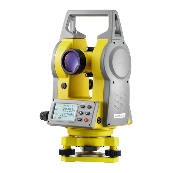
DT-2
Manual
Nivel System DT-2 Manual
Hide thumbs
1
2
Table Of Contents
3
4
5
6
7
8
9
10
11
12
13
14
15
16
17
18
19
20
21
22
23
24
25
26
27
28
29
30
31
32
33
34
35
36
37
38
39
40
page
of
40
Go
/
40
Contents
Table of Contents
Bookmarks
Table of Contents
Table of Contents
Application
Nomenclature
Display and Display Mark
Operating Keyboard and Operating Key
Preparative before Measurement
Leveling the Instrument
Power Switch on
Battery Power Display
Change the Battery
Angle Measurement
Measuring a HA R and Vertical Angle
R /Ha L
Setting a Horizontal Angle
Repetition Angle Measurement
Measuring a Percent of Grade (Slope Measurement)
Distance Measurement
Use with the Range Finder (EDM )
Join with the EDM
Distance Measuring
Recording and Outputting Data
Communication Interface
Recording Measurement Data
Memory Mode
Function Setting
Function Setting Method
Time Setting
Vertical Angle 0 Error and Collimation Error and
Tilt Angle Compensator 0 Error
Other Function
Measuring Distance
Tilt Correction Function
Illuminate and the Timing Close
Check and Adjustment
Check and Adjust Plate Level
Check and Adjust Circular Level
Check and Adjust Vertical Cross-Hair
Calibration of the E-Bubble
Collimation of the Instrument Sight Line
Check and Adjust Optical Plummet
Check and Adjust Laser Plummet
Check and Adjust Laser Pointer
Tribrach
Error Display
Specifications
Standard Accessories
Advertisement
Quick Links
Download this manual
Table of
Contents
Previous
Page
Next
Page
1
2
3
4
5
Advertisement
Table of Contents
Need help?
Do you have a question about the DT-2 and is the answer not in the manual?
Ask a question
Questions and answers
Related Manuals for Nivel System DT-2
Laser Level Nivel System DL60 Instruction Manual
Digital electronic level (2 pages)
Laser Level Nivel System DT-5 Manual
(40 pages)
Laser Level Nivel System NL610 Manual
Rotation laser (32 pages)
Laser Level Nivel System NL301 Manual
Rotation laser (25 pages)
Laser Level Nivel System NL410 Manual
Rotating laser levels nivel system (28 pages)
Laser Level Nivel System NL740R Manual
Dual grade laser (28 pages)
Laser Level Nivel System EL-32 Manual
Electronic level (28 pages)
Laser Level Nivel System CL4D-G Manual
Cross line laser (17 pages)
Laser Level Nivel System NL540 Manual
Dual grade laser (28 pages)
Laser Level Nivel System MC-1D Manual
Laser machine control system (8 pages)
Laser Level Nivel System NL Series Manual
Rotation laser (13 pages)
Laser Level Nivel System NL510 Manual
Rotation laser (32 pages)
Laser Level Nivel System CL8 Manual
(12 pages)
Laser Level Nivel System CL1G Manual
Cross line laser (21 pages)
Laser Level Nivel System CL4 Manual
Laser crossliners (13 pages)
Laser Level Nivel System CL1R Manual
(29 pages)
This manual is also suitable for:
Dt-5
Table of Contents
Print
Rename the bookmark
Delete bookmark?
Delete from my manuals?
Login
Sign In
OR
Sign in with Facebook
Sign in with Google
Upload manual
Upload from disk
Upload from URL


Need help?
Do you have a question about the DT-2 and is the answer not in the manual?
Questions and answers