Table of Contents
Advertisement
Quick Links
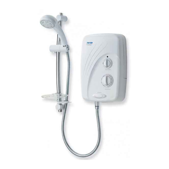
T900pi
pumped
electric shower
! IMPORTANT !
Under *NO circumstances must
this shower be connected directly
to a mains water supply.
It is designed for GRAVITY FED
COLD WATER systems ONLY !
*
Failure to comply may invalidate product warranty
Installation and
operating
instructions
I
nstallers please note these InstructIons
are to be left wIth the user
IMPORTANT SAFETY ADVICE
•
The shower unit MUST BE switched off at the isolating switch when
not in use. This is a safety procedure recommended for all electrical
appliances.
•
The showerhead and hose supplied with this product are a safety
critical part of your shower. Failure to use genuine Triton parts may
cause injury and invalidate your guarantee.
2180306J - June 2019
Advertisement
Table of Contents

Related Manuals for Triton T900pi


Summary of Contents for Triton T900pi
- Page 1 This is a safety procedure recommended for all electrical appliances. • The showerhead and hose supplied with this product are a safety critical part of your shower. Failure to use genuine Triton parts may cause injury and invalidate your guarantee. 2180306J - June 2019...
- Page 2 T900pi INTRODUCTION - PLEASE READ PLEASE READ THIS IMPORTANT SAFETY INFORMATION Products manufactured by Triton are safe and without risk provided they are installed, used and maintained in good working order in accordance with our instructions and recommendations. ARNING: DO NOT operate shower if frozen, or suspected of being frozen.
- Page 3 DO NOT operate the shower if water ceases to ow during use or if water has entered inside the unit because of an incorrectly tted cover. IMPORTANT - PLEASE READ THESE T900pi WARNING: If restarting the shower immediately after stopping, be aware that a slug of GENERAL GUIDANCE NOTES BEFORE PROCEEDING hot water will be expelled for the first few seconds.
- Page 4 Advice to users This book contains all the necessary fitting and IMPORTANT: When first installed the unit operating instructions for your Triton pumped will be empty. It is essential the unit should electric shower. Please read them carefully and contain water before the elements are keep for future reference.
-
Page 5: Table Of Contents
Energy Efficiency Class Energy Efficiency (%) Annual Electricity Consumption (kwh) Sound Power Level (db) To check the product suitability for commercial and multiple installations, please contact Triton’s speci cation advisory service before installation. Please see back of book for contact information. -
Page 6: Main Components
T900pi MAIN COMPONENTS Main components Fig.1 Inside unit (fig.1) Top cable/pipe entry Motor unit Pump unit Bleed screw Wall screw fixing Feed pipe Thermal safety cut-out (main) Terminal block Can and element assembly 10. Power selector 11. Pressure switch 12. Temperature valve 27.5... -
Page 7: Electrical Requirements
T900pi ELECTRICAL REQUIREMENTS Fig.3 Triton Showers, Triton Road, Nuneaton, Warwickshire, CV11 4NR WARNING! W-006-A xxxx THIS APPLIANCE MUST BE EARTHED The installation, supply cable and circuit protection must conform with BS 7671 (IEE wiring regulations) and be suf cient for the amperage required. - Page 8 T900pi A 45 amp double pole isolating switch with 9.3 In any event, it is essential that individual a minimum contact gap of 3 mm in both site conditions are assessed by a competent poles must be incorporated in the circuit.
-
Page 9: Water Requirements
T900pi WATER REQUIREMENTS Water requirements WARNING! Minimum capacity 114 litres (25 gallons) Cold water Under no circumstances must cistern this pumped shower be connected Stop Gate Mains electric supply valve valve directly to the mains water supply. (via double pole switch) -
Page 10: Siting Of The Shower
T900pi SITING OF THE SHOWER Siting of the shower WARNING! FOR EASE OF SERVICING, THE UNIT MUST The shower must not be positioned W-008-A ALWAYS BE MOUNTED ON THE SURFACE OF where it will be subjected to freezing TILED WALLS. NEVER TILE UP TO THE UNIT. -
Page 11: Fitting The Shower To The Wall
T900pi FITTING THE SHOWER TO THE WALL Fitting the shower to the wall Fig.7 WARNING! Check there are no hidden cables or pipes before drilling holes for wall W-005-A plugs. Use great care when using power tools near water. The use of a residual current device (RCD) is recommended. - Page 12 T900pi Screw two upper fixing screws into position Fig.10 leaving the base of the screw heads protruding 6mm out from the wall. Hook the backplate over the top screws and fit the lower fixing screw into position. DO NOT fully tighten the screws at this stage,...
-
Page 13: Plumbing Connections
T900pi PLUMBING CONNECTIONS Plumbing connections WARNING! Plumbing to be carried out before wiring The outlet of the shower acts as a DO NOT use jointing compounds on any pipe W-004-A vent and MUST NOT be connected to fittings for the installation. -
Page 14: Electrical Connections
T900pi ELECTRICAL CONNECTIONS Electrical connections Fig.13 SWITCH OFF THE ELECTRICITY SUPPLY AT THE MAINS. Fig.13 shows a schematic wiring diagram. The cable entry points are shown in fig.1. The cable can be surface clipped, hidden or via 20mm conduit. Note: Metal conduit entry can only be from the rear. -
Page 15: Commissioning
T900pi COMMISSIONING Commissioning Fig.15 WARNING! Before normal operation of the W-001-A shower, it is essential the following commissioning procedure is completed correctly. The first operation of the shower is intended to flush out any remaining unit debris and to make sure the heater unit contains water before the elements are switched on. - Page 16 T900pi Attached to the START/STOP button inside the Fig.19 cover is a two-wire lead. The socket on the end of this lead must be connected to the plug that is situated at the bottom of the right-hand side of the backplate unit (fig.19).
-
Page 17: Operating The Shower
T900pi OPERATING THE SHOWER Operating the shower Fig.22 WARNING! Before normal operation of the Power on indicator W-001-A shower, it is essential the following commissioning procedure is completed correctly. To start the shower Pressing the START/STOP button (fig.22) switches on the pump allowing water to immediately flow through the unit. - Page 18 T900pi To adjust the shower temperature WARNING! The shower temperature is altered by increasing After any servicing of mains water or decreasing the flow rate of the water through supply, always flush out the pipework the shower via the temperature control.
-
Page 19: Operating Functions
T900pi OPERATING FUNCTIONS Operating functions Fig.23 Power on indicator (fig.23) Cold The power neon will light when the START/STOP button is pressed. This indicates that power is on to the pump and power selector. Low water pressure cut-out Full Should the water pressure fall below the... -
Page 20: Instructions For Installers And Service Engineers Only
T900pi INSTRUCTIONS FOR INSTALLERS AND SERVICE ENGINEERS ONLY Instructions for installers and service engineers only CLEANING THE INLET FILTER Fig.24 It is recommended that the filter is periodically cleaned in order to maintain the performance of the shower. It is essential that this operation is carried out by a competent person. -
Page 21: Spare Parts
T900pi SPARE PARTS Spare parts Ref. Description Part No. 1. Motor and pump assembly ..84000120 2. Connecting pipe – lower....7052554 Connecting pipe – upper ....7052555 3. Thermal cut-out ......22012680 4. Terminal block ......22009230 5. Can assembly 9.0kW (230V) ...... -
Page 22: Fault Finding
T900pi FAULT FINDING IMPORTANT: Switch off the electricity at the mains supply and remove the circuit fuse before attempting any fault finding inside the unit. Fault finding Problem/Symptom Cause Action/Cure 1 Shower inoperable, 1.1 Interrupted power 1.1.1 Check if a general power cut. Check other no water flow when supply. - Page 23 T900pi FAULT FINDING Problem/Symptom Cause Action/Cure 5 During use, the 5.1 Interrupted power 5.1.1 See 1.1.1 and 1.1.2. water flow ceases supply. abruptly. 5.2 Solenoid valve 5.2.1 Switch off immediately. Have solenoid malfunction (pump checked by a competent electrician or contact still operates).
- Page 24 Earthridge International Ltd Triton Showers Triton Road Maynooth Nuneaton Co. Kildare. Warwickshire, CV11 4NR Triton is a division of Norcros Group (Holdings) Limited TRITON reserve the right to change product specifi cation without prior notice. E&OE. © TRITON SHOWERS 2019...
Need help?
Do you have a question about the T900pi and is the answer not in the manual?
Questions and answers