Advertisement
—— Instruction Manual ——
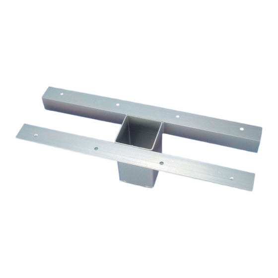
Second Story Volleyball Socket Form
Floating floor socket installation on floating floor with lower levels or crawl space below concrete or
While more difficult to install, it is possible to use floor sockets on upper level gym floors. Unless you
are experienced in this technique it is wise to consult a professional installer. There are many variables
that need to be considered so the instructions below should only be used as a general guideline.
Proper net tensioning transfers up to 10,000 pounds of force to the socket and its housing so it is
imperative to use anchors that will withstand this load. If your gym floor, subfloor or other variables
differ from those described, installer will need to adjust the installation procedure to suit the actual
conditions. Installer and owner bear full responsibility for proper installation.
Item
Qty
Description
A
1
VB230 Concrete Form
B
1
Floor Plate
Inspect all contents prior to installation. Report any missing parts to dealer immediately
Read all instructions before proceeding.
1.
Once desired location of sockets in the gym is determined you will need to determine the type of
subfloor, the location and orientation of all support structure, whether flooring supports are steel, wood
or pre-stressed concrete and whether it is possible to feasibly access the area directly below the desired
socket locations. Sometimes it is necessary to drill a small hole on the desired centerline of the socket
through the wood floor, concrete and support structure to determine location below. If this location is
not used the hole in the floor needs to be filled.
2.
If it is determined that the locations of the Floor Sockets (C) selected will allow for installation of a
VB230 Concrete Form (A) below the floor, use the Floor Plate (B) and pencil to draw a circle on the
finished floor at each Floor Socket (C) location.
3.
Measure the distance from the top of the floor to the subfloor surface below. If the distance is greater
than 3" you will not be able to use VB230 Concrete Form (A) without field modifications.
4.
Cut a hole through the wood floor that is 2" SMALLER in diameter than the circle drawn from
instruction #2. This should be approximately 6" in diameter. CAUTION: If you cut the hole on the
larger pencil circle it will not be possible to install the Floor Plate (B) properly. You may need to rout
relief in the wood to accommodate Floor Socket (C) installation. See Figure 1.
Date: 5/21/18
Rev: I.R.
VB230
Application:
wooden subfloors.
Notice:
Caution:
P A R T S L I S T
B.A.
N.J.C.
Item
Qty
Description
C
1
Floor Socket
File: \pub\inst\vb230
1
Customer Service
(800) 247-7668
.
Ref#: 960965
Advertisement
Table of Contents

Subscribe to Our Youtube Channel
Related Manuals for Bison VB230


Summary of Contents for Bison VB230
- Page 1 If it is determined that the locations of the Floor Sockets (C) selected will allow for installation of a VB230 Concrete Form (A) below the floor, use the Floor Plate (B) and pencil to draw a circle on the finished floor at each Floor Socket (C) location.
- Page 2 With the Floor Socket (C) assembly properly sitting in the hole, inspect the installation area from the lower level or crawl space. Install VB230 Concrete Form (A) to the underside of the floor with the grout retainer centered on the Floor Socket (C) assembly. Make sure to use the proper sized anchors or attachment hardware.
- Page 3 FIGURE 1...
Need help?
Do you have a question about the VB230 and is the answer not in the manual?
Questions and answers