
Related Manuals for Spektrum DX6


Summary of Contents for Spektrum DX6
- Page 1 6-Channel, 10-Model Memory DSM Park yer and Micro Helicopter System Distributed by www.modelflight.com.au...
-
Page 2: Welcome To The World Of Spektrum Technology
Park yers Only The DX6 system is designed for park yer type aircraft only. This includes all forms of compact electric and non-powered airplanes as well as micro electric helicopters. While the system has more than adequate range for these types of aircraft, it is imperative that the system not be used in larger aircraft that could exceed the range. -
Page 3: Table Of Contents
GERMAN:Zur Ansicht der Bedienunsanleitung in den Deutsch besuchen Sie bitte www.spektrumrc.com SPANISH:Para ver este manual en Español entra en www.spektrumrc.com Table of Contents Welcome to the World of Spektrum™ Technology ..............2 Park yers Only........................2 How DSM™ Works .........................2 Transmitter......................2 Receiver........................2 Alternate Languages........................3... - Page 4 Aileron-to-Rudder Mixing Switch Selection............44 Elevator-to-Flap Mixing ..................45 Elevator-to-Flap Mixing Switch Selection .............46 Differential ......................47 Flap-to-Elevator Offset Trim..................48 Programmable Mixing (A, B, C)................49 Offset ........................52 Programming a Rudder Dual Rate.................53 CHAPTER 8: DATA SHEET ....................55 SPEKTRUM DX6 • TABLE OF CONTENTS Distributed by www.modelflight.com.au...
- Page 5 Programming a Rudder Dual Rate.................87 CCPM Swashplate Mixing..................88 CCPM Servo Locations ..................90 CCPM Servo Connections..................91 Important Gyro Information...................91 CHAPTER 8: DATA SHEET ....................92 Warranty One Year Warranty ........................93 FCC Information ........................94 Notes ............................95 SPEKTRUM DX6 • TABLE OF CONTENTS Distributed by www.modelflight.com.au...
-
Page 6: Aircraft Quick Start: 4-Channel Airplane W/Single Rates
If you wish to change these fail-safe positions after the Quick Start Setup see page 24 for binding details. Important: Remove the bind plug after binding. Model Type Selection Selecting the Airplane Mode SPEKTRUM DX6 • INTRODUCTION Distributed by www.modelflight.com.au... -
Page 7: Digital Trim Settings
If necessary move the throttle, aileron, elevator, and rudder trims to neutral by moving each trim lever while noting the trim position on the screen. The throttle, aileron, elevator and rudder trims should all be set to 0. Servo Reversing Establishing Servo Direction SPEKTRUM DX6 • AIRCRAFT QUICK START GUIDE Distributed by www.modelflight.com.au... -
Page 8: Travel Adjustment
Mixing, etc., see the appropriate pages in the Table of Contents. Note: If your airplane’ s ailerons are controlled independently by two servos see “Wing Type Selection” on page 33 for specifics on programming flaperons. SPEKTRUM DX6 • AIRCRAFT QUICK START GUIDE Distributed by www.modelflight.com.au... -
Page 9: Helicopter Quick Start: 5-Channel Mechanical Mix Helicopters
If you wish to change these fail-safe positions after the Quick Start Setup, see page 60 for binding details. Important: Remove the bind plug after binding. Model Type Selection Selecting the Helicopter Mode. SPEKTRUM DX6 • AIRCRAFT QUICK START GUIDE Distributed by www.modelflight.com.au... -
Page 10: Digital Trim Settings
If necessary move the throttle, aileron, elevator, and rudder trims to neutral by moving each trim lever while noting the trim position on the screen. The throttle, aileron, elevator and rudder trims should all be set to 0. Servo Reversing Establishing Servo Direction SPEKTRUM DX6 • HELICOPTER QUICK START GUIDE Distributed by www.modelflight.com.au... -
Page 11: Travel Adjustment
Travel Adjustment Establishing Servo Travel SPEKTRUM DX6 • HELICOPTER QUICK START GUIDE Distributed by www.modelflight.com.au... -
Page 12: Pitch Curve
Pitch Curve Adjusting the Normal Pitch Curves The DX6 offers three independent pitch curves with three adjustable points per curve. This function allocatesa separate pitch curve setting during Normal, Stunt, and Throttle Hold modes to maximize ight performance. Once the pitch curves are established, each can be activated in ight, using the two-position ight mode switch and the throttle hold switch. -
Page 13: Throttle Curve
This completes the basic Quick Start setup for your helicopter . For additional featues like additional pitch and throttle curves, throttle hold, remote gyro gain, etc., see the appropriate pages in the Table of Contents. Note: For CCPM helicopter setup see page 88. SPEKTRUM DX6 • HELICOPTER QUICK START GUIDE Distributed by www.modelflight.com.au... -
Page 14: Important Gyro Information
When the DX6 receiver is rst turned on, the servos are driven to their fail-safe positions until the receiver connects to the DX6 transmitter. This can take several seconds. If the fail-safe position for rudder is different than the rudder trim position, it is possible that the gyro will establish the fail-safe position as neutral instead of the trimmed neutral position. -
Page 15: Helicopter Speci C Features
• Easy bind plug Receiver Speci cations • Model#: AR6000 • Type: 6-channel park yer only • Dimensions: 39 x 39 x 9mm • Weight: 7 grams • Frequency: 2.400–2.485 • Receiver antennas: 3.75” SPEKTRUM DX6 • SPECIFICATIONS Distributed by www.modelflight.com.au... -
Page 16: Servo Speci Cations
• Model #: SPMS75 • Dimensions: (LxWxH) 23 x 12 x 24mm • Weight: 7.5 grams • Torque: 17.2 oz @4.8V • Speed: .12 sec @4.8V • Operating voltage: 3.2–6.0V • Motor type: Coreless SPEKTRUM DX6 • SPECIFICATIONS Distributed by www.modelflight.com.au... -
Page 17: Charging The Transmitter
Subsequent charges of 10–12 hours (approximately overnight) are recommended. Many modelers fast-charge their batteries. The DX6 does not have a charging diode in the circuit and will allow most fast chargers to be used, however, it is imperative to understand that all Spektrum™ transmitters have a center pin negative charge connector. -
Page 18: Trainer System
Trainer System The DX6 features a built-in trainer system. The transmitter can be used as either a master (trainer) or as a slave ® (trainee). The DX6 is compatible with all other Spektrum™ and JR radios that have built-in trainer systems. An optional Trainer Cord (SPM6805) is needed. -
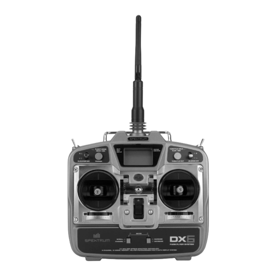
Page 19: Control Identi Cation And Location - Airplane
Control Identi cation and Location - Airplane SPEKTRUM DX6 • INTRODUCTION Distributed by www.modelflight.com.au... - Page 20 Distributed by www.modelflight.com.au...
-
Page 21: Chapter 1: Transmitter Controls
2–3 seconds. A signi cant feature found only with Digital Trims is the ability for the DX6 to automatically store the trim values in system memory. This eliminates the need for previously found software functions like T rim Offset Memory (airplane), or Rudder Offset Memory and Stunt Trims (heli). -
Page 22: Lithium Battery
LITHIUM BATTERY Note: The DX6 has a 5-year lithium battery to protect your programmed data against main transmitter battery failure. If your system displays “error” or your data resets to the factory defaults, return your transmitter to Horizon Service Center (see page 93) for lithium battery replacement. -
Page 23: Range Testing
RANGE TESTING Before each ying session, and especially with a new model, it is important to perform a range check. The DX6 incorporates a system which, when the bind button on the back of the transmitter is pressed, the output power reduces allowing for a range check. -
Page 24: Binding
BINDING Each Spektrum™ transmitter has a GUID (Globally Unique Identi er) code. Binding is the process of programming the receiver to recognize the GUID of a single speci c transmitter. Binding teaches the receiver the speci c GUID of that transmitter, so that the receiver will only listen to the information from its previously bound transmitter and ignores everything else. -
Page 25: Chapter 2: Connections
CHAPTER 2: CONNECTIONS CONNECTIONS SPEKTRUM DX6 • DX6 AIRCRAFT PROGRAMMING GUIDE Distributed by www.modelflight.com.au... -
Page 26: Chapter 3: Key Input And Display
CHAPTER 3: KEY INPUT AND DISPLAY Two input keys are located at the lower faceplate of the DX6 transmitter. The keys are used to access and program the transmitter. Each key can be moved up or down using your thumbs CHAPTER 4: BATTERY ALARM AND DISPLAY When the transmitter battery drops below 9.0 volts, the display will start to ash “BAT”... -
Page 27: Chapter 5: Input Mode And Function
DIRECT TRIM ACCESS DISPLAY The Direct Trim function of the DX6 can be accessed through the use of any of the four digital trims levers (throttle, aileron, elevator, or rudder). When a trim input is given, the screen will automatically change to show the trim value for that particular channel. -
Page 28: System Mode
Information for each function is located on the page number listed next to the function name. To exit the system mode, press the buttons upward SCROLL INCREASE simultaneously or turn off the transmitter. SPEKTRUM DX6 • AIRCRAFT PROGRAMMING GUIDE Distributed by www.modelflight.com.au... -
Page 29: Function Mode
Scroll button to scroll through the functions one by one as shown in the owchart below. Once the appropriate function is selected, press the button downward to select the appropriate channel. Use the CHANNEL INCREASE buttons to adjust the values displayed on the screen. DECREASE SPEKTRUM DX6 • DX6 AIRCRAFT PROGRAMMING GUIDE Distributed by www.modelflight.com.au... -
Page 30: Chapter 6: Functions (System Mode)
CHAPTER 6: FUNCTIONS (SYSTEM MODE) MODEL TYPE SELECTION Two types of aircraft programming are available with the DX6, airplane (AC) and helicopter (HE). When entering the model type selection function, the current model type will appear on the screen. (This will be the current model type set as the factory default or the last model used.) When you press the... -
Page 31: Data Reset
5. Press the button to access the Model Select function. SCROLL 6. To exit, press the buttons up simultaneously. SCROLL INCREASE SPEKTRUM DX6 • DX6 AIRCRAFT PROGRAMMING GUIDE Distributed by www.modelflight.com.au... -
Page 32: Dual Rate Switch Selection
INCREASE DECREASE (E.A, A., E. or CF) 5. Press the button to access the Wing Type selection function. SCROLL 6. To exit, press the buttons simultaneously. SCROLL INCREASE SPEKTRUM DX6 • AIRCRAFT PROGRAMMING GUIDE Distributed by www.modelflight.com.au... -
Page 33: Wing Type Selection
Use sub-trims for individual neutral adjustment. Adjust the ailerons travel values by increasing or decreasing the aileron travel adjust. D/R and expo values, as well as differential, are also available in the appropriate screens. SPEKTRUM DX6 • DX6 AIRCRAFT PROGRAMMING GUIDE Distributed by www.modelflight.com.au... -
Page 34: V-Tail
DECREASE also possible to activate both the Flaperon (FPR) and V-Tail (VTL) functions to work simultaneously. While it is unlikely to have an aircraft that would require both, it is possible. SPEKTRUM DX6 • AIRCRAFT PROGRAMMING GUIDE Distributed by www.modelflight.com.au... -
Page 35: Delta-Wing Mixing
TO ACTIVATE DELTA-WING (DLT) MIXING (WING TYPE MODE) 1. In System Setup mode, press the button until “MIX WNG” appears on the screen. SCROLL 2. Press the button to activate Delta-Wing Mixing. DECREASE SPEKTRUM DX6 • DX6 AIRCRAFT PROGRAMMING GUIDE Distributed by www.modelflight.com.au... -
Page 36: Model Selection
MODEL SELECTION The DX6 has memory for ten models. It can store the settings for ten airplanes, ten helicopters, or any combination of both types of models. ACCESSING THE MODEL SELECTION FUNCTION 1. Press the buttons upward simultaneously and hold. -
Page 37: Model Name Entry
MODEL NAME ENTRY The DX6 allows a three-digit name to be input for each of the ten models available. The current model will be displayed in the normal display. This feature helps identify different aircraft types or model setups. ACCESSING THE MODEL NAME ENTRY FUNCTION 1. -
Page 38: Chapter 7: Functions (Function Mode)
5. Press the button to change the servo direction. INCREASE DECREASE 6. Press the button to access the Dual Rate function. SCROLL 7. To exit, press the buttons simultaneously. SCROLL CHANNEL SPEKTRUM DX6 • AIRCRAFT PROGRAMMING GUIDE Distributed by www.modelflight.com.au... -
Page 39: Dual Rate
CHANNEL switch positions. 10. Press the button to access the Exponential Rate feature. SCROLL 11. To exit, press the buttons simultaneously. SCROLL INCREASE SPEKTRUM DX6 • DX6 AIRCRAFT PROGRAMMING GUIDE Distributed by www.modelflight.com.au... -
Page 40: Exponential
EXPONENTIAL Programmable exponential adjustments are offered on the aileron and elevator channels on the DX6 system. Exponential is a function that allows you to tailor the response rate of the controls as compared to the stick inputs. The purpose of exponential is to reduce the sensitivity in the middle portion of stick movement, while still allowing full travel at the end of the stick movement. -
Page 41: Sub-Trim
INCREASE DECREASE 6. Press the button to access the travel adjustment function. SCROLL 7. To exit, press the buttons simultaneously. SCROLL INCREASE SPEKTRUM DX6 • DX6 AIRCRAFT PROGRAMMING GUIDE Distributed by www.modelflight.com.au... -
Page 42: Travel Adjustment
6. The same may be done for all channels. 7. Press the button to access the aileron- to-rudder mixing function. SCROLL 8. To exit, press the buttons simultaneously. SCROLL INCREASE SPEKTRUM DX6 • AIRCRAFT PROGRAMMING GUIDE Distributed by www.modelflight.com.au... -
Page 43: Aileron-To-Rudder Mixing
AILERON-TO-RUDDER MIXING On some types of aircraft, it is desirable to mix aileron and rudder to make coordinated turns. The DX6 allows the mixing of aileron-to-rudder and allows you to adjust the amount and direction of aileron to rudder mixing. -
Page 44: Aileron-To-Rudder Mixing Switch Selection
INCREASE DECREASE 3. Press the button to access the elevator-to- ap mixing function. SCROLL 4. To exit, press the buttons simultaneously. SCROLL INCREASE SPEKTRUM DX6 • AIRCRAFT PROGRAMMING GUIDE Distributed by www.modelflight.com.au... -
Page 45: Elevator-To-Flap Mixing
“MIX E-F” appears on the screen. SCROLL 4. Press the buttons simultaneously to set the elevator-to- ap mixing direction. CHANNEL INCREASE 5. Press the button to set the elevator-to- ap mixing value. INCREASE DECREASE SPEKTRUM DX6 • DX6 AIRCRAFT PROGRAMMING GUIDE Distributed by www.modelflight.com.au... -
Page 46: Elevator-To-Flap Mixing Switch Selection
SCROLL the system mode. If aperons are not activated, pressing the button will access the ap-to-elevator SCROLL offset function. 4. To exit, press the buttons simultaneously. SCROLL INCREASE SPEKTRUM DX6 • AIRCRAFT PROGRAMMING GUIDE Distributed by www.modelflight.com.au... -
Page 47: Differential
INCREASE DECREASE 6. Press the button to access the ap-to-elevator offset trim function. SCROLL 7. To exit, press the buttons simultaneously. SCROLL INCREASE SPEKTRUM DX6 • DX6 AIRCRAFT PROGRAMMING GUIDE Distributed by www.modelflight.com.au... -
Page 48: Flap-To-Elevator Offset Trim
Note: It is helpful to have the flap switch on when making this adjustment. 5. Press the button to access the Programmable Mix function. SCROLL 6. To exit, press the buttons simultaneously. SCROLL INCREASE SPEKTRUM DX6 • AIRCRAFT PROGRAMMING GUIDE Distributed by www.modelflight.com.au... -
Page 49: Programmable Mixing (A, B, C)
PROGRAMMABLE MIXING (A, B, C) In airplane mode, the DX6 offers three programmable mixes (A, B, and C) allowing numerous mixing options. This function allows mixing any one channel to any other channel. The mix can remain ON at all times, or be switched ON/ OFF in ight using a number of different switches. - Page 50 “MIX ASW” appears. CHANNEL 2. Press the button to select the switch to be used to activate the mixing, or leave on INCREASE DECREASE if a constant mix is desired. SPEKTRUM DX6 • AIRCRAFT PROGRAMMING GUIDE Distributed by www.modelflight.com.au...
- Page 51 “ON” is selected, it will be necessary to move the selected switch to the on (or active) position to adjust the mixing value. “OF” will appear on the screen if the selected mixing switch is in the off position. SPEKTRUM DX6 • DX6 AIRCRAFT PROGRAMMING GUIDE Distributed by www.modelflight.com.au...
-
Page 52: Offset
“OF” will appear on the screen if the selected mixing switch is in the off position. SPEKTRUM DX6 • AIRCRAFT PROGRAMMING GUIDE Distributed by www.modelflight.com.au... -
Page 53: Programming A Rudder Dual Rate
Note: A positive value increases the rudder travel, while a negative value decreases the rudder travel. 7. Move the rudder stick in the opposite direction to adjust that direction’s value. SPEKTRUM DX6 • DX6 AIRCRAFT PROGRAMMING GUIDE Distributed by www.modelflight.com.au... - Page 54 “MIX ASW” appears. CHANNEL 2. Press the button to select the switch to be used to activate the mixing, or leave on INCREASE DECREASE if a constant mix is desired. SPEKTRUM DX6 • AIRCRAFT PROGRAMMING GUIDE Distributed by www.modelflight.com.au...
-
Page 55: Chapter 8: Data Sheet
CHAPTER 8: Data Sheet SPEKTRUM DX6 • DX6 AIRCRAFT PROGRAMMING GUIDE Distributed by www.modelflight.com.au... - Page 56 SPEKTRUM DX6 • AIRCRAFT PROGRAMMING GUIDE Distributed by www.modelflight.com.au...
-
Page 57: Chapter 1: Transmitter Controls
2–3 seconds. A signi cant feature found only with Digital Trims is the ability for the DX6 to automatically store the trim values in system memory. This eliminates the need for previously found software functions like T rim Offset Memory (airplane), or Rudder Offset Memory and Stunt Trims (Heli). -
Page 58: Lithium Battery
LITHIUM BATTERY Note: The DX6 has a 5-year lithium battery to protect your programmed data against main transmitter battery failure. If your system displays “error” or your data resets to the factory defaults, return your transmitter to Horizon Service Center (see page 93) for lithium battery replacement. -
Page 59: Range Testing
RANGE TESTING Before each ying session and especially with a new model, it is important to perform a range check. The DX6 incorporates a system which when the bind button on the back of the transmitter is pressed, the output power is reduced allowing for a range check. -
Page 60: Binding
BINDING Each Spektrum™ transmitter has a GUID (Globally Unique Identi er) code. Binding is the process of programming the receiver to recognize the GUID of a single speci c transmitter. Binding teaches the receiver the speci c GUID of that transmitter so that the receiver will only listen to the information from its previously bound transmitter and ignores everything else. -
Page 61: Chapter 2: Connections
CHAPTER 2: CONNECTIONS CONNECTIONS SPEKTRUM DX6 • DX6 HELICOPTER PROGRAMMING GUIDE Distributed by www.modelflight.com.au... -
Page 62: Chapter 3: Key Input And Display
CHAPTER 3: KEY INPUT AND DISPLAY KEY INPUT AND DISPLAY Two input keys are located at the lower faceplate of the DX6 transmitter. The keys are used to access and program the transmitter. Each key can be moved up or down using your thumbs CHAPTER 4: BATTERY ALARM AND DISPLAY When the transmitter battery drops below 9.0 volts, the display will start to ash “BAT”... -
Page 63: Chapter 5: Input Mode And Function
DIRECT TRIM ACCESS DISPLAY The Direct Trim function of the DX6 can be accessed through the use of any of the four digital trims levers (throttle, aileron, elevator, or rudder). When a trim input is given, the screen will automatically change to show the trim value for that particular channel. -
Page 64: System Mode
Information for each function is located on the page number listed next to the function name. To exit the system mode, press the buttons upward SCROLL INCREASE simultaneously or turn off the transmitter. SPEKTRUM DX6 • HELICOPTER PROGRAMMING GUIDE Distributed by www.modelflight.com.au... -
Page 65: Function Mode
Once the SCROLL SCROLL appropriate function is selected, press the button downward to select the appropriate channel. Use the CHANNEL buttons to adjust the values displayed on the screen. INCREASE DECREASE SPEKTRUM DX6 • DX6 HELICOPTER PROGRAMMING GUIDE Distributed by www.modelflight.com.au... -
Page 66: Chapter 6: Functions (System Mode)
CHAPTER 6: FUNCTIONS (SYSTEM MODE) MODEL TYPE SELECTION Two types of aircraft programming are available with the DX6, airplane (AC) and helicopter (HE). When entering the model type selection function, the current model type will appear on the screen. (This will be the current model type set as the factory default or the last model used.) When you press the... -
Page 67: Data Reset
5. Press the button to access the Model Select function. SCROLL 6. To exit, press the buttons up simultaneously. SCROLL INCREASE SPEKTRUM DX6 • DX6 HELICOPTER PROGRAMMING GUIDE Distributed by www.modelflight.com.au... -
Page 68: Dual Rate Switch Selection
(E.A, A., INCREASE DECREASE E. or CF) 5. Press the button to access the Wing Type selection function. SCROLL 6. To exit, press the buttons simultaneously. SCROLL INCREASE SPEKTRUM DX6 • HELICOPTER PROGRAMMING GUIDE Distributed by www.modelflight.com.au... -
Page 69: Gear/Gyro Switch Selection
GEAR/GYRO SWITCH SELECTION The DX6 gear/gyro switch selection function enables the dual rate values of the gyro to be combined with one of four switches ( ight mode, throttle hold, aileron dual rate, elevator dual rate). This feature is for use with gyros that offer a dual rate sensitivity adjustments.. -
Page 70: Model Selection
MODEL SELECTION The DX6 has memory for ten models. It can store the settings for ten airplanes, ten helicopters, or any combination of both types of models. ACCESSING THE MODEL SELECTION FUNCTION 1. Press the buttons upward simultaneously and hold. -
Page 71: Model Name Entry
MODEL NAME ENTRY The DX6 allows a three-digit name to be input for each of the ten models available. The current model will be displayed in the normal display. This feature helps identify different aircraft types or model setups. ACCESSING THE MODEL NAME ENTRY FUNCTION 1. -
Page 72: Chapter 7: Functions (Function Mode)
5. Press the button to change the servo direction. INCREASE DECREASE 6. Press the button to access the Dual Rate function. SCROLL 7. To exit, press the buttons simultaneously. SCROLL CHANNEL SPEKTRUM DX6 • HELICOPTER PROGRAMMING GUIDE Distributed by www.modelflight.com.au... -
Page 73: Dual Rate
CHANNEL switch positions. 10. Press the button to access the Exponential Rate feature. SCROLL 11. To exit, press the buttons simultaneously. SCROLL INCREASE SPEKTRUM DX6 • DX6 HELICOPTER PROGRAMMING GUIDE Distributed by www.modelflight.com.au... -
Page 74: Exponential
EXPONENTIAL Programmable exponential adjustments are offered on the aileron and elevator channels on the DX6 system. Exponential is a function that allows you to tailor the response rate of the controls as compared to the stick inputs. The purpose of exponential is to reduce the sensitivity in the middle portion of stick movement, while still allowing full travel at the end of the stick movement. -
Page 75: Sub-Trim
INCREASE DECREASE 6. Press the button to access the travel adjustment function. SCROLL 7. To exit, press the buttons simultaneously. SCROLL INCREASE SPEKTRUM DX6 • DX6 HELICOPTER PROGRAMMING GUIDE Distributed by www.modelflight.com.au... -
Page 76: Travel Adjustment
6. The same may be done for all channels. 7. Press the button to access the aileron- to-rudder mixing function. SCROLL 8. To exit, press the buttons simultaneously. SCROLL INCREASE SPEKTRUM DX6 • HELICOPTER PROGRAMMING GUIDE Distributed by www.modelflight.com.au... -
Page 77: Throttle Hold
-2 (1/2 trim) to +15 (full high trim). 6. Press the button to access the pitch curve function. SCROLL 7. To exit, press the buttons simultaneously. SCROLL INCREASE SPEKTRUM DX6 • DX6 HELICOPTER PROGRAMMING GUIDE Distributed by www.modelflight.com.au... -
Page 78: Pitch Curve
PITCH CURVE The DX6 offers three independent pitch curves with three adjustable points per curve. This function allocatesa separate pitch curve setting during Normal, Stunt, and Throttle Hold modes to maximize ight performance. Once the pitch curves are established, each can be activated in ight using the two-position ight mode switch and the throttle hold switch. - Page 79 SCROLL Note: If throttle hold is not activated, the Throttle Curve function will be accessed. 9. To exit, press the buttons simultaneously. MODE CHANNEL SPEKTRUM DX6 • DX6 HELICOPTER PROGRAMMING GUIDE Distributed by www.modelflight.com.au...
-
Page 80: Throttle Curve
The throttle curve is in the stunt mode when the ight mode switch is in the forward position. Note: In Stunt mode (S), the high position of the throttle curve is preset to 100%, and is not adjustable. SPEKTRUM DX6 • HELICOPTER PROGRAMMING GUIDE Distributed by www.modelflight.com.au... - Page 81 Then, repeat Steps 5 SCROLL and 6 to adjust. 7. Press the button once to access the Revolution Mixing function. SCROLL 8. To exit, press the buttons simultaneously. SCROLL INCREASE SPEKTRUM DX6 • DX6 HELICOPTER PROGRAMMING GUIDE Distributed by www.modelflight.com.au...
-
Page 82: Revolution Mixing
CHANNEL INCREASE direction, press the buttons simultaneously again. CHANNEL INCREASE 6. Press the button to access the Programmable Mix A function. SCROLL 7. To exit, press the buttons simultaneously. SCROLL INCREASE SPEKTRUM DX6 • HELICOPTER PROGRAMMING GUIDE Distributed by www.modelflight.com.au... -
Page 83: Programmable Mixing (A)
PROGRAMMABLE MIXING (A) The DX6 in Helicopter mode offers one (1) programmable mix to be used for a number of different purposes. The functions allow mixing any one channel to any other channel. The mix can remain on at all times or be switched off in ight using a number of different switches. - Page 84 “MIX ASW” appears. CHANNEL 2. Press the button to select the desired switch to be used to activate the mixing, or INCREASE DECREASE leave on if a constant mix is desired. SPEKTRUM DX6 • HELICOPTER PROGRAMMING GUIDE Distributed by www.modelflight.com.au...
- Page 85 “ON” is selected, it will be necessary to move the selected switch to the on, or active, position to adjust the mixing value. “OF” will appear on the screen if the selected mixing switch is in the off position. SPEKTRUM DX6 • DX6 HELICOPTER PROGRAMMING GUIDE Distributed by www.modelflight.com.au...
-
Page 86: Offset
“OF” will appear on the screen if the selected mixing switch is in the off position. SPEKTRUM DX6 • HELICOPTER PROGRAMMING GUIDE Distributed by www.modelflight.com.au... -
Page 87: Programming A Rudder Dual Rate
Note: A positive value will increase the rudder travel, while a negative value will decrease the rudder travel. 7. Move the rudder stick in the opposite direction to adjust that direction’s value. SPEKTRUM DX6 • DX6 HELICOPTER PROGRAMMING GUIDE Distributed by www.modelflight.com.au... -
Page 88: Ccpm Swashplate Mixing
Servo-CCPM identi cation and connection. THREE-SERVO (120 DEGREES) CCPM MIXING Note: The CCPM Swashplate Mixing function is designed for use only with helicopters that incorporate the 120° three-servo CCPM control system. SPEKTRUM DX6 • HELICOPTER PROGRAMMING GUIDE Distributed by www.modelflight.com.au... - Page 89 (+100). INCREASE DECREASE 7. Press the button once to access the servo reversing function. SCROLL 8. To exit, press the buttons simultaneously. SCROLL INCREASE SPEKTRUM DX6 • DX6 HELICOPTER PROGRAMMING GUIDE Distributed by www.modelflight.com.au...
-
Page 90: Ccpm Servo Locations
AUX 1 (Pitch) Servo: We will refer to this servo as the “Right” servo. The channel number for this servo is CH6. Please refer to the CCPM connections chart below for clari cation. SPEKTRUM DX6 • HELICOPTER PROGRAMMING GUIDE Distributed by... -
Page 91: Ccpm Servo Connections
When the DX6 receiver is rst turned on, the servos are driven to their fail-safe positions until the receiver connects to the DX6 transmitter. This can take several seconds. If the fail-safe position for rudder is different than the rudder trim position, it is possible that the gyro will establish the fail-safe position as neutral instead of the trimmed neutral position. -
Page 92: Chapter 8: Data Sheet
CHAPTER 8: Data Sheet SPEKTRUM DX6 • HELICOPTER PROGRAMMING GUIDE Distributed by www.modelflight.com.au... -
Page 93: One Year Warranty
One Year Warranty This Spektrum™ product is guaranteed against workmanship and manufacturing defects for a period of 1 year from the original date of purchase. This warranty is limited to the original purchaser and cannot be transferred. Warranty repair will cover all units except those that have been modi ed, misused, improperly installed, or serviced by an unauthorized service center. -
Page 94: Fcc Information
This product contains a radio transmitter with wireless technology which has been tested and found to be compliant with the applicable regulations governing a radio transmitter in the 2.400GHz to 2.4835GHz frequency range. Canada Belgium Denmark France Finland Germany Italy Netherlands Spain Sweden SPEKTRUM DX6 • WARRANTY Distributed by www.modelflight.com.au... -
Page 95: Notes
Notes SPEKTRUM DX6 • WARRANTY Distributed by www.modelflight.com.au... - Page 96 © 2005 Horizon Hobby, Inc. 4105 Fieldstone Road Champaign, Illinois 61822 (877) 504-0233 horizonhobby.com SPMM** #8259 Distributed by www.modelflight.com.au...
Need help?
Do you have a question about the DX6 and is the answer not in the manual?
Questions and answers
The Throttel ( left )and Elevater ( right ) has changed positions on DX6 G3
To fix the throttle and elevator position swap on the Spektrum DX6 G3, you need to change the throttle limiting wedges when switching between different modes. Follow these steps:
1. Remove a screw and wedge from the top and bottom of the throttle gimbal.
2. Move the gimbals slightly to access the components.
3. Install the wedges on the other gimbal using two screws.
After making these changes, ensure that the transmitter is properly calibrated by moving the control sticks to their extremes and centers when prompted on the calibration screen.
This answer is automatically generated