
Related Manuals for Marshall Electronics V-R902DLW


Summary of Contents for Marshall Electronics V-R902DLW
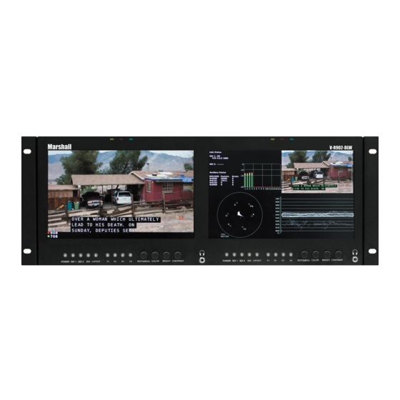
- Page 1 Marshall Electronics V-R902DLW Model Dual 9” Desktop and Rack Mount Dual Link / Waveform Monitor Operating Instructions Edition 2 Revision 0W...
- Page 2 Page intentionally left blank...
-
Page 3: Table Of Contents
Table of Contents Installation and Initial Setup ------------------------------------------------------------------------------------------------------5 Top and Front Panel Features ----------------------------------------------------------------------------------------------------7 Rear Panel Features-----------------------------------------------------------------------------------------------------------------8 Compatible Input Formats---------------------------------------------------------------------------------------------------------9 MAIN MENU AND NAVIGATION------------------------------------------------------------------------------------------------ 10 Using the RotoMenu knob ------------------------------------------------------------------------------------------------------ 10 Marker Setup Submenu ..................................10 Video Config Submenu ..................................13 Audio Config Submenu..................................16 Color Config Submenu..................................17 System Config Submenu..................................17 OSD Config Submenu ..................................19... - Page 4 Page intentionally left blank...
-
Page 5: Installation And Initial Setup
■ The V-R902DLW can be mounted in any standard EIA 19” equipment rack. The attached rack ears can be angled to provide the user control over the viewing angle. Adequate ventilation is required when installed to prevent possible damage to the monitor’s internal components. - Page 6 Page intentionally left blank...
-
Page 7: Top And Front Panel Features
Top and Front Panel Features RotoMenu™ Knob Power Button The RotoMenu™ knob allows for accessing and navigating the Use the power button to toggle between ON and STANDBY main menu using only a single knob. modes. The LED on the POWER button will illuminate fully when the unit is in STANDBY mode. -
Page 8: Rear Panel Features
SDI Inputs / Outputs and DVI-I Input RS-422/RS-485 Serial Interface The V-R902DLW has two 3G-SDI inputs and two active loop- The RS-422/485 ports are used to remotely control the IMD or through outputs. SDI 1 and SDI 2 can be used simultaneously all DLW features. -
Page 9: Compatible Input Formats
Compatible Input Formats The following video standards are supported by the V-R902DLW: SDI Inputs 525i, 625i/50 720p/29.97, 30, 50, 59.94, 60 1080p/23.98, 23.98sF, 24, 24sF, 25, 29.97, 30 1035i/59.94, 60 1080i/ 50, 59.94, 60 3G – Level A and Level B YCbCr, YCbCr+A, RGB, RGB+A 1080p/ 60, 59.94, 50... -
Page 10: Main Menu And Navigation
MAIN MENU AND NAVIGATION Access and navigate the main menu using the RotoMenu™ knob: Main Menu Using the RotoMenu knob • Press the RotoMenu™ knob to enter the main menu. • Rotate the knob to scroll up or down in the main menu or each submenu. •... - Page 11 ■ Marker Enable Use this function to enable or disable screen markers. Using a function key or switching marker settings from the menu will automatically enable the markers. ■ 16:9 Markers Use this setting to superimpose one of 10 markers on the screen when in 16:9 or Full Screen mode. This setting is disabled when the aspect ratio is set to 4:3, or when Pixel-to-Pixel mode is enabled.
- Page 12 4:3 Marker Examples: OFF (No Marker) 90% Safe Area ■ Marker Background Use this setting to choose how selected markers are displayed on the screen: • Off The marker is superimposed on the complete image. • 50% Gray Screen area beyond the marker is shown at 50% intensity. •...
-
Page 13: Video Config Submenu
Video Config Submenu Use the Video Configuration submenu to select various video settings such as monochrome mode or blue-only mode. Video Configuration Submenu ■ CTemp/Gamma Use this setting to choose one of three color temperature / gamma presets: • D55 (5500K) •... - Page 14 640x480 pixels in the center of the screen. The surrounding screen area will be black. ■ Aspect Ratio Settings Use this menu option to switch between several aspect ratio settings. As the V-R902DLW monitor has a native resolution of 1366x768 RGB pixels, incoming images are automatically scaled to fit the screen: •...
- Page 15 ■ Delete Gamma Use this function to delete any customized User calibration that has been loaded on to the system via Marshall Electronics’ custom calibration application. Please contact Marshall Electronics for more information. ■ Framelock Mode Framelock is used to designate the selected input as a reference for synchronizing image scaling when using the DLW monitor.
-
Page 16: Audio Config Submenu
■ HDMI CSC Auto (HDMI input only, via the DVI-I interface) The HDMI CSC Auto setting is used to accommodate newer HDMI interfaces that send colorspace signaling in the HDMI data stream. If this setting is set to On, the monitor will automatically determine which colorspace setting to use. If this setting is set to Off, or your HDMI signal does not contain colorspace signaling, the DVI-D CSC Mode described above will determine the colorspace configuration. -
Page 17: Color Config Submenu
Color Config Submenu Use the Color Configuration submenu to adjust the Red, Green and Blue Offset and Gain values of the two SDI channels, the DVI- D input and DVI-A input. EFor the DVI-I input, you can adjust the Offset and Gain for either a DVI-D or DVI-A input. The Reset option allows you to return to the default settings for each individual channel. - Page 18 • Marker Toggle between different Screen Markers • Center Marker Display/hide the Center Marker • Marker Enable Display/hide on screen markers • Marker Backgrd Change how markers are displayed on the screen • IMD State Display/hide IMD text • Anc. Time Code Display/hide time code •...
-
Page 19: Osd Config Submenu
• Anc. Time Code Display/hide time code • Marker Level Rotate amongst marker settings The following settings are activated only when the Green, Red or Yellow Pin is brought into a LOW state by connecting it with one of the GND pins. Once the Tally Pin is brought HIGH again (remove the connection to GND), the settings will be deactivated. •... - Page 20 Status Display ■ OSD Tally Use this setting to choose how tally is displayed on the screen. The available OSD Tally options depend on the Tally Source selected in the IMD Configuration submenu When the Tally Source is set to Standard (contact closure), OSD Tally can be set to Off, RGY, RG, or GR: •...
- Page 21 When the Tally Source is set to TSL/MEI 422, OSD Tally can be set to Off or IMD: • Off On-screen tally is disabled • IMD Red, yellow, and green tally is displayed according the protocol commands. Green, red, and yellow colors are shown individually on either the bottom left or right of the screen.
-
Page 22: Imd Config Submenu
■ Overview The V-R902DLW features an In-Monitor Display (IMD) with the ability to display on-screen text and tally in three colors. IMD text, color, and alignment can be assigned to each screen locally using menu options (see below). Alternately, IMD text and tally can be remotely controlled via the RS-422/485 serial interface using several industry-standard protocols, including TSL v4.0 and Image Video. - Page 23 This protocol setting accepts Image Video commands via MEI protocol, for use when an Image Video controller is connected to the Marshall Network Controller box. ■ Tally Source The V-R902DLW OSD tally can be controlled in a variety of different ways. Use the Tally Source setting to choose how tally is controlled: Standard Use the Standard setting to control tally via contact closure on the HD-15 tally interface.
-
Page 24: Imd Fixed Config Submenu
Press RotoMenu™ knob to edit the IMD Name. Rotate the RotoMenu™ knob to move the cursor. Press the RotoMenu™ knob with the cursor on the character to be changed, then rotate the knob to scroll through the character set . Press the RotoMenu™... -
Page 25: Closed Captioning Submenu
■ 608 Service The EIA-608 caption protocol defines four channels of caption information. The V-R902DLW monitor can only display one of these four channels at any point in time. With the 608 Service selection, you can select which of the four streams to render on the screen. -
Page 26: Wave/Vector Submenu
Use the Wave/Vector submenu to change the location of the Waveform Monitor and Vectorscope, as well as the data displayed on the Waveform monitor or the Vectorscope on the V-R902DLW monitor. The Waveform Monitor can also be customized to conform to different scales, to display different colors, differentiate data with Limits. The Vectorscope targets can also be changed in this menu. - Page 27 • RGB Parade The R (shown in Red), G (shown in Green) and B (shown in Blue) components of the signal are displayed from left to right. • RGB Overlay The RGB components of the signal are overlaid. ■ Waveform Scale Use the Waveform scale option to switch between different graticule units on the Waveform display.
-
Page 28: Ancillary Submenu
■ Limit Min Use this to set the desired minimum for the Limit display of the waveform monitor. Any Waveform data that goes below this Limit Max will be displayed in red. ■ Vectorscope Targets Use the Vectorscope Targets option to set your Vectorscope targets up for 75% or 100% color bar signals. You can also set your Vectorscope Targets to the OFF position. -
Page 29: Service Submenu
Service Submenu ■ Software Version Display The Main Board, Keypad, and FPGA software version numbers are displayed. Service Menu The following information is displayed: • rel: Release Package version number • ipa Input processor firmware • dlw FPGA Version • ipap Product Type •... - Page 30 Page intentionally left blank...
-
Page 31: Specifications
Specifications PANEL Activation requires contact closure of pin to ground ■ on the HD-15 connector: Screen Size 9” Diagonal Display Area (h x v) 193.92 x 116.35 mm Pixels 1280 x RGB x 768 Viewing Angle (h x v) 170° x 170° Brightness 350 cd/m2 Contrast Ratio... -
Page 32: Dimensions
Dimensions... - Page 33 Page intentionally left blank...
-
Page 34: Maintenance
Warranty Marshall Electronics warranties to the first consumer that this V-R902DLW LCD monitor will, under normal use, be free from defects in workmanship and materials, when received in its original container, for a period of one year from the purchase date. - Page 35 Page intentionally left blank...
- Page 36 Marshall Electronics, Inc. 1910 East Maple Ave. El Segundo, CA 90245 Tel: (800) 800-6608 / (310) 333-0606 • Fax: 310-333-0688 www.LCDRacks.com • sales@lcdracks.com...
Need help?
Do you have a question about the V-R902DLW and is the answer not in the manual?
Questions and answers