Table of Contents
Advertisement
Quick Links
Advertisement
Table of Contents

Related Manuals for Elatec TWN3 Multi ISO


Summary of Contents for Elatec TWN3 Multi ISO
- Page 1 Transponder Reader Multi ISO Technical Manual Doc.-Rev. 1.05...
-
Page 2: Table Of Contents
Elatec GmbH Content Introduction ........................5 Installation of Nano Module Multi ISO ................. 6 Mechanical Outline ......................... 6 Pinning ............................. 6 Electrical Characteristics ....................... 7 External Connections ......................7 2.4.1 Antenna ............................7 2.4.2 Asynchronous Serial Connection (UART) ..................8 2.4.3... - Page 3 Elatec GmbH 6.2.1 STX ............................... 19 6.2.2 Station ID ............................19 6.2.3 Length ............................19 6.2.4 Data ............................... 19 6.2.5 Block Check Character (BCC) ...................... 19 6.2.6 ETX ............................... 19 6.2.7 Example ............................20 6.2.8 Remarks ............................20 Instruction Set ....................... 21 Command Overview ......................
- Page 4 Elatec GmbH Get Station ID ‘g’ .......................... 46 7.6.1 Antenna Power Off ‘poff’ ......................46 7.6.2 Antenna Power On ‘pon’ ....................... 46 7.6.3 Get Version ‘v’ ..........................46 7.6.4 Reset ‘x’ ............................46 7.6.5 7.6.6 Break ............................. 46 Read GPIO ‘ir’ ..........................47 7.6.7...
-
Page 5: Introduction
Elatec GmbH 1. Introduction This document is the reference guide for the transponder reader family TWN3 Multi ISO and Nano Module Multi ISO. The readers are using the same reading technology, so this document is applicable for both devices. Note: In order to use the functionality, which is described in this document, your Multi ISO reader needs a firmware version V1.15 or above. -
Page 6: Installation Of Nano Module Multi Iso
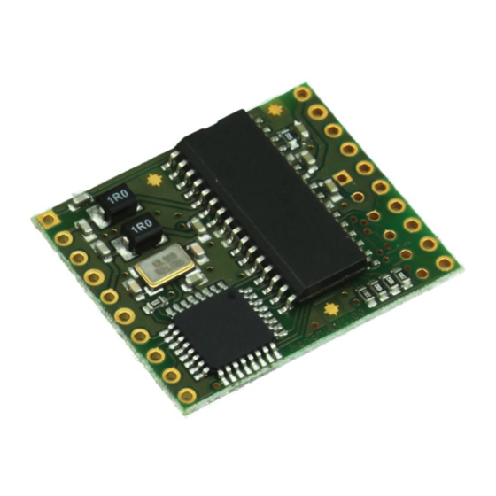
Elatec GmbH 2. Installation of Nano Module Multi ISO This chapter covers the installation of Nano Module Multi ISO in an embedded environment. 2.1 Mechanical Outline 30.48mm x 25.40mm x 3.7mm (1.2” x 1” x 0.15”) Dimensions: Connectors are in 2.54mm (0.1”) grid. -
Page 7: Electrical Characteristics
Elatec GmbH 2.3 Electrical Characteristics Frequency 13.56MHz Power supply 4.5V - 5.5V DC Current consumption RF field off: 20mA RF field on: Typically 120mA, depending on antenna 2.4 External Connections The schematic below shows a typical application circuit for operating the reader module. -
Page 8: Asynchronous Serial Connection (Uart)
Elatec GmbH 2.4.2 Asynchronous Serial Connection (UART) Because Nano Module Multi ISO is transmitting and receiving TTL levels, it can be directly connected to a microcontroller. If you plan to run Nano Module Multi ISO at a PC, an appropriate interface converter circuit must be connected. -
Page 9: Supported Transponders
Elatec GmbH 3. Supported transponders ISO14443A ISO14443B ISO15693 Mifare Calypso ICODE SLI Classic 1k, 4k CEPAS Tag-it DESFire EV1 Moneo Legic Advant Light SRI512, SRT512, SRI4K, SRIX4K Inside Contactless PicoPass Mini Inside Contactless PicoPass HID ICLASS Plus S, X HID ICLASS... -
Page 10: Register Set
Elatec GmbH 5. Register Set The reader has several system flags customizing its behavior. The flags are stored non-volatile in its EEPROM. It is recommended to keep all bits labeled RFU at their default state to guarantee further compatibility. Please consider that if any register is written, the reader needs a reset so that the changes may take effect. -
Page 11: Unique Device Id (00H
Elatec GmbH 5.2 Unique Device ID (00h … 04h) The Unique Device ID is factory programmed and cannot be changed. It forms a unique 40 bit ID of the reader. 5.3 Station ID (0Ah) In ASCII mode, the Station ID has principally no influence on the functional behavior of the reader. -
Page 12: Extendid
Elatec GmbH Character Transponder type ISO14443A, e.g. Mifare® PicoPass / ICLASS ISO14443B, e.g. SRIX4K ISO15693, e.g. I•Code SLI 5.4.5 ExtendID If set, the unique serial number (UID) of the transponder is extended by a single prefix byte. This bit has only effect for ISO14443A transponders. -
Page 13: Resetting The Baudrate To Default
Elatec GmbH 5.5.1 Resetting the Baudrate to Default The reader has a built-in mechanism to reset the baudrate to the default value of 9600 bps. This is useful, if no communication is possible any more due to an errant setting of the Baudrate control register. -
Page 14: Operation Mode Register 1(0Eh)
Elatec GmbH 5.6 Operation Mode Register 1(0Eh) The Operation Mode Register 1 defines which tag types the reader shall support. Including or excluding of transponder types has direct influence in the transponder detection speed of the reader. Operation Mode Register 1... -
Page 15: Reset Off Time (14H)
Elatec GmbH 5.8 Reset Off Time (14h) The Reset Off Time register represents the time in milliseconds, the RF-field is switched off, after a reading attempt has finished. This register is used for the continuous read mode („c‟). The higher the value of the register, the more energy can be saved. As soon as there is a transponder in range, the field turned on permanently. -
Page 16: Application Family Identifier Afi (16H)
Elatec GmbH 5.10 Application Family Identifier AFI (16h) The Application Family Identifier (AFI) is only supported by ISO15693 transponders. If the value of this register is different from 00h, the AFI is used. This means, that only transponders containing an identical AFI will answer to the reader. -
Page 17: Installation Identifier (E0H
Elatec GmbH Byte value Corresponding transponder type Mifare® Mini Mifare® Classic 1K Mifare® Classic 4K Mifare® Plus S Mifare® Plus X Mifare® Ultralight / Ultralight C Mifare® DESFire Unknown ISO14443A transponder I•Code SL2 I•Code SL2-S Tag-it™ HF-I Plus Inlay Tag-it™ HF-I Plus Chip Tag-it™... -
Page 18: Beep Tone And Length (Ffh)
Elatec GmbH 5.14 Beep Tone and Length (FFh) This register defines the beep tone (frequency) and beep length. It is only implemented on Nano Module Multi ISO. Beep Tone and Length Register Bit 7 Bit 6 Bit 5 Bit 4... -
Page 19: Communication Protocol
Elatec GmbH 6. Communication Protocol 6.1 ASCII Protocol The ASCII protocol has been designed for easy handling. Data is always transmitted in hexadecimal notation, i.e. 5E. Every time the reader is powered up, a startup message is displayed. On the terminal screen this should look like this: MultiISO 1.15<CR><LF>... -
Page 20: Example
Elatec GmbH 6.2.7 Example This example shows how to log into sector 0 of a Mifare card, using transport key FFh: ® Station ID Length Data 6C 00 FF 0D 6.2.8 Remarks If an invalid instruction frame is received (e.g. BCC is wrong) or if the requested Station ID does not match the internal ID of the reader, the command is not executed. -
Page 21: Instruction Set
Elatec GmbH 7. Instruction Set 7.1 Command Overview 7.1.1 Common Commands Command Description For details view chapter ‘ ’ Cancel command 7.6.6 ‘as’ AES data encryption/decryption 7.6.15 ‘b’ Beep 7.6.11 ‘c’ Continuous read mode 7.3.1 ‘.’ Stop continuous read mode (in noisy environment) 7.6.6... -
Page 22: Mifare® Classic Specific Commands
Elatec GmbH 7.1.2 Mifare® Classic Specific Commands For details view Command Description chapter ‘+’ Increment value block 7.4.4.3 ‘-’ Decrement value block 7.4.4.4 ‘=’ Copy value block 7.4.4.5 ‘l’ Login (authenticate tag) 7.4.1.1 7.4.1.2 ‘rv’ Read value block 7.4.4.2 ‘wm’... -
Page 23: Transponder Serial Number Related Commands
Elatec GmbH 7.3 Transponder Serial Number Related Commands 7.3.1 Continuous read mode „c‟ The reader reads and displays serial numbers continuously while one or more tags remain in the field. This command stops as soon as any character is sent to the reader if the Noisy Environment bit is cleared. -
Page 24: Multitag Selection / Tag List 'M
Elatec GmbH 7.3.3 MultiTag Selection / Tag List „m‟ This command detects several tags at the same time. It replaces the fast select command („s‟) in multiple tag surroundings. The MultiTag list command lists all present tags with their serial numbers. -
Page 25: Mifare® Plus Virtual Card Select 'Nvcs
Elatec GmbH 7.3.4 Mifare® PLUS Virtual Card Select „nvcs‟ Use this command to retrieve the „real‟ UID of the transponder in a virtual card environment. If a card is configured to show random IDs, the virtual card select command offers the possibility to retrieve the UID in a fast and secure way. -
Page 26: Data Transaction Related Commands
Elatec GmbH 7.4 Data Transaction Related Commands 7.4.1 Authenticate Tag 7.4.1.1 Mifare® Classic Login ‘l’ This command performs an authentication into a specific sector of a Mifare® Classic transponder. Only one transponder and only one sector can be accessed at the same time. Prior access, the transponder must be selected by either single tag or MultiTag selection commands. -
Page 27: Mifare® Ultralight C Login 'L
Elatec GmbH 7.4.1.2 Mifare® Ultralight C Login ‘l’ This command performs an authentication into a Mifare® Ultralight C transponder. The authentication scheme into this transponder type is different to Mifare® Classic due to the fact, that Ultralight C uses Triple-DES cryptography. -
Page 28: Mifare® Plus Login 'Nl
Elatec GmbH 7.4.1.3 Mifare® PLUS Login ‘nl’ Mifare® PLUS offers various authentication features to the user. Depending on the desired transaction or configured security level of the transponder, the appropriate authentication procedure must be chosen by the user. The reader always demands an AES key for authentication; if the transponder is configured to security level 2, optionally a Crypto1 key can be passed to the reader. -
Page 29: Login In Multiple Tag Surroundings
Elatec GmbH Examples Command Description ‘nl00AA50<CR>’ Authenticate to sector 00 using EEPROM AES key 00, type A ‘nl02BB51<CR>’ Authenticate to sector 02 using EEPROM AES key 01, type B ‘nl28AA52<CR>’ Authenticate with card master key using EEPROM AES key 02, KeyType is ignored but has to be transmitted to the reader. -
Page 30: Read Data Block 'R' / 'Rb
Elatec GmbH 7.4.2 Read Data Block „r‟ / „rb‟ This command reads an entire data block from a transponder. The range of valid block addresses depends on the used transponder. If you are working with Mifare® cards, keep in mind that any read- or write access requires a successful login into the respective sector. -
Page 31: Write Data Block 'W' / 'Wb
Elatec GmbH 7.4.3 Write Data Block „w‟ / „wb‟ This command writes an entire data block to the transponder. The range of valid block addresses depends on the used transponder. A read after write is done automatically to ensure data integrity. If you are working with Mifare®... -
Page 32: Mifare® Value Block Related Commands
Elatec GmbH 7.4.4 Mifare® Value Block Related Commands A sector of a Mifare® transponder may contain so-called „value blocks‟. A value block is a usual data block, where the information is stored in a certain format. Special Mifare® commands like increment or decrement may be applied to such a block, e.g. -
Page 33: Create Value Block 'Wv
Elatec GmbH 7.4.4.1 Create Value Block ‘wv’ Use this command to format a common data block as a value block. The range of valid block addresses depends on the used transponder type. You must log into the respective sector before this command can be executed. -
Page 34: Increment Value Block
Elatec GmbH 7.4.4.3 Increment Value Block ‘+’ Use this command to increment a value block by a defined value. A read after increment is performed automatically. The command fails if the specified block is not formatted as value block. You must log into the respective sector before this command can be executed. -
Page 35: Copy Value Block
Elatec GmbH 7.4.4.5 Copy Value Block ‘=’ Use this command to copy a value block to another value block of the same sector. A read after copy is performed automatically. The command fails if one of the specified blocks is not in value format. You must log into the respective sector before this command can be executed. -
Page 36: Mifare® Plus Related Commands
Elatec GmbH 7.4.5 Mifare® PLUS Related Commands 7.4.5.1 Write Personalization Data ‘nwp’ Use this command to transmit personalization data to the transponder in SL0. At least Card Master key, Card configuration key, Level 2 switch key (Mifare® PLUS X only) and Level 3 switch key must be written in order to personalize the transponder. -
Page 37: Commit Personalization 'Ncp
Elatec GmbH 7.4.5.2 Commit Personalization ‘ncp’ Use this command to finish personalization and to switch the transponder from SL0 to SL1. If the personalized transponder is a so-called „L3‟-card, the transponder is switched to SL3. This command is only supported if the transponder is in SL0. -
Page 38: Proximity Check 'Npc
Elatec GmbH Answer Answer Description Data<CR><LF> Written data ‘F<CR><LF>’ Error: General failure ‘R<CR><LF>’ Error: Parameter out of range Examples Command Description nw00AA001122334455 Change AES sector key, sector 00, key type A to 00112233445566778899AABBCCDDEEFFh 66778899AABBCCDDEEFF nw01BB000000000000 Change AES sector key, sector 01, key type B to 00000000000000000000000000000000h... -
Page 39: Transparent Iso14443-4 Transponder Access 'T
Elatec GmbH 7.4.6 Transparent ISO14443-4 Transponder Access „t‟ This command is used to communicate with ISO14443-4 Type A/B compatible transponders. Data passed as argument is forwarded to the transponder, any response received is transmitted to the host as answer. The transponder must be selected prior further data access. Basic communication parameters like communication timeout and maximum frame size are negotiated by the reader with the card automatically;... -
Page 40: Setup Related Commands Of The Reader
Elatec GmbH 7.5 Setup Related Commands of the Reader 7.5.1 Read Byte from EEPROM „rp‟ Use this command to read a byte from the internal reader EEPROM. Only the configuration bank is accessible by the user, it is not possible to read any stored keys. The address byte ranges from 00h to FFh. -
Page 41: Set Configuration Flags 'Of
Elatec GmbH 7.5.3 Set Configuration Flags „of‟ Use this command to set or clear the Configuration Flags of the reader. In contrast to the EEPROM registers, the settings of the „of‟ command are volatile, this means, they are taking effect on the behavior of the reader at once and they are lost, when a reset occurs or the reader is powered down. -
Page 42: Set Configuration Register 'Og
Elatec GmbH 7.5.4 Set Configuration Register „og‟ Use this command to set the Configuration registers of the reader. In contrast to the EEPROM registers, the settings of the „og‟ command are volatile, this means they are taking effect on the behavior of the reader at once and they are lost, when a reset occurs or the reader is powered down. -
Page 43: Include Tag Type 'O+A' / 'O+B' / 'O+P' / 'O+S' / 'O+V
Elatec GmbH 7.5.6 Include Tag Type „o+a‟ / „o+b‟ / „o+p‟ / „o+s‟ / „o+v‟ Use this command to include specific transponder types to the transponder search. In contrast to the EEPROM register, the settings of the „o+‟ command are volatile, this means they are taking effect on the behavior of the reader at once and they are lost when a reset occurs or the reader is powered down. -
Page 44: Key Management
Elatec GmbH 7.5.8 Key Management 7.5.8.1 Write Mifare® Classic Key ‘wm’ Use this command to store a Mifare® Classic authentication key into the EEPROM of the reader. The reader is able to store up 32 keys. The key locations are write-only, so the keys can‟t be read back. -
Page 45: Sam Related Commands
Elatec GmbH 7.5.9 SAM related Commands The reader supports the connection of an ISO 7816 compatible SAM card (Secure Access Module). The SAM card is driven by the reader via an ISO 7816 compatible UART, using the following default parameters: f = 1.043 MHz (13.56MHz/13);... -
Page 46: Miscellaneous Commands
Elatec GmbH 7.6 Miscellaneous Commands 7.6.1 Get Station ID „g‟ Use this command to retrieve the station ID of the reader. Command: ‘g’ Answer Description Data<CR><LF> Station ID of the reader (1 byte) 7.6.2 Antenna Power Off „poff‟ Use this command to turn off the RF-field and save energy. All present tags in the antenna field are powered down and reset. -
Page 47: Read Gpio 'Ir
Elatec GmbH 7.6.7 Read GPIO „ir‟ Use this command to read a specified GPIO. The GPIO is switched to input prior reading. Command: ‘ir[GPIONumber]’ Answer Answer Description Data<CR><LF> Status of specified GPIO: 00 means Low; 01 means High. Example Command Description ‘ir02’... -
Page 48: Beep 'B
Elatec GmbH 7.6.11 Beep „b‟ Use this command to perform a beep. Tone length and frequency are depending on the settings in the Beep tone and length register. The command answers with the value written in the register. Command: ‘b’... -
Page 49: Aes Data Encryption/Decryption 'As
Elatec GmbH 7.6.15 AES Data Encryption/Decryption „as‟ Use this command to perform AES encryption/decryption on 16 byte data blocks. Keys can be passed via serial connection, optionally the internally stored keys can be used. Command: ‘as’[Options][Key/KeyNumber][Data] Parameters Description [Options] Option byte (1 byte) [Key/KeyNumber] Key (16 bytes) / Key number (1 byte), 00h…0Fh... -
Page 50: Des / Triple-Des Data Encryption/Decryption 'Ds
Elatec GmbH 7.6.16 DES / Triple-DES Data Encryption/Decryption „ds‟ Use this command to perform encryption/decryption operations on 8 byte data blocks. The command offers both Single-DES and Triple-DES crypto functions. Triple-DES cryptology is based on two keys data encryption/decryption. Keys can be passed via serial connection, optionally the internally stored keys can be used. -
Page 51: Typical Data Transaction Procedures
Elatec GmbH 8. Typical Data Transaction Procedures 8.1 Mifare® Classic / Mifare® PLUS The following diagram shows the typical command-flow in order to access the data area of a Mifare® Classic / PLUS transponder: Select transponder ‚s‟ / ‚m‟ Transponder... -
Page 52: Mifare® Ultralight
Elatec GmbH 8.2 Mifare® Ultralight In contrast to Mifare® Classic transponders, no login is required to access the EEPROM memory: Select transponder ‚s‟ / ‚m‟ Transponder selected? Perform read/ write actions ‚r‟ / ‚w‟ Read/write successful? Read/write completed? Page 52 of 65... -
Page 53: Mifare® Ultralight C
Elatec GmbH 8.3 Mifare® Ultralight C Accessing the EEPROM depends on the settings of the transponder, e.g. if an authentication is required. The following diagram shows the typical command-flow in order to access the data area of a Mifare® Ultralight C transponder:... -
Page 54: I•Code Sli / Srx
Elatec GmbH 8.4 I•Code SLI / SRX The following diagram shows the typical command-flow in order to access the data area of an I•Code SLI or SRX transponder. No authentication is required prior accessing the data area: Select transponder ‚s‟ / ‚m‟... -
Page 55: Memory Organization Of Mifare® Transponders
Elatec GmbH 9. Memory Organization of Mifare® Transponders 9.1 Mifare® Classic 1k A Mifare® Classic 1k transponder consists of 16 sectors. Each sector is organized in four data blocks. A data block stores 16 bytes of data. The following table shows the memory organization of a Mifare®... -
Page 56: Mifare® Classic 4K
Elatec GmbH 9.2 Mifare® Classic 4k A Mifare® Classic 4k transponder consists of 40 sectors. In contrast to the Mifare® standard 1k transponder, the 4k version has a different memory organization, shown in the following table: Sector Block addresses Login sector... -
Page 57: Mifare® Plus
Elatec GmbH 9.3 Mifare® PLUS Mifare® PLUS 2K/4K transponders have a similar memory organization like Mifare® Classic 4K. However, a 2Kbyte card only has the lower 32 Sectors built-in: Bytes Sector Block addresses Sector Block addresses 00h...03h 40h...43h 04h...07h 44h...47h 08h...0Bh... -
Page 58: Mifare® Ultralight
Elatec GmbH 9.4 Mifare® Ultralight A Mifare® Ultralight transponder consists of 16 pages with 4 bytes each. The UID is read-only and is also mapped into the memory area. Page Byte 0 Byte 1 Byte 2 Byte 3 Access rights... -
Page 59: Mifare® Ultralight C
Elatec GmbH 9.5 Mifare® Ultralight C A Mifare® Ultralight C transponder consists of 48 pages with 4 bytes each. The UID is read-only and is also mapped into the memory area. The 16 bytes Triple-DES key is stored in the last 4 pages of the transponder. -
Page 60: Example: Writing The Triple-Des Key
Elatec GmbH 9.5.1 Example: Writing the Triple-DES Key This chapter shows how to write the Triple-DES key into the transponder. On example of Key1 = 0001020304050607h and Key2 = 08090A0B0C0D0E0Fh the command sequence shown in the table below has to be executed for writing the key. The following preconditions... -
Page 61: Mifare® Plus
Elatec GmbH 10. Mifare® PLUS 10.1 Security Levels Mifare® PLUS supports four security levels. The initial delivery configuration is SL0. Within this level, cards must be personalized. After that, the card is switched to a higher security level. Once a card has been switched to a higher level, it cannot be switched back to a lower level. -
Page 62: Application Hints
Elatec GmbH 10.2 Application Hints Have a look at the following hints when developing your Mifare® PLUS application. They will help you choosing the correct transponder and reader in order to satisfy your needs: In SL3, value formats are only supported by Mifare® PLUS X cards ... -
Page 63: Firmware Update
Elatec GmbH 11. Firmware Update The reader contains a bootloader program which makes firmware updates possible. Complete the following steps to update the firmware: Power up the reader Ensure that the reader runs at 9600 bps Start the application WinFlash.exe, you should see the following window ... -
Page 64: Firmware History
Elatec GmbH 12. Firmware History Version Changes V1.00 Initial release V1.01 Baudrate control register implemented Baudrate recovery mechanism implemented Mifare® Ultralight C supported DES/3DES crypto command implemented V1.02 PicoPass support (UID only) V1.03... -
Page 65: Trademarks
Elatec GmbH 13. Trademarks All referenced brands, product names, service names and trademarks mentioned in this document are the property of their respective owners. Page 65 of 65...
Need help?
Do you have a question about the TWN3 Multi ISO and is the answer not in the manual?
Questions and answers