Advertisement
Available languages
Available languages
Quick Links
Write Model Number From Box Here:
© COPYRIGHT 2021 by Russell Brands, LLC
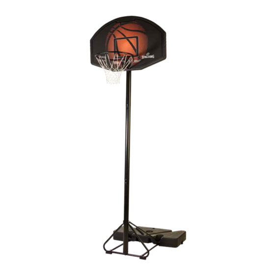
Portable Basketball System
Owners Manual
Toll-Free Customer Service Number for U.S: 1-800-558-5234,
For Canada: 1-800-284-8339,
For Europe: +353 51 379777 (Sweden: 009 555 85234),
For Australia: 1300 367 582
This manual, accompanied by sales receipt,
should be saved and kept on hand as a
convenient reference, as it contains important
1
English
Español
WARNING!
READ AND UNDERSTAND
OPERATOR'S MANUAL
BEFORE USING THIS UNIT.
FAILURE TO FOLLOW
OPERATING
COULD RESULT IN INJURY
OR DAMAGE TO PROPERTY.
information about your model.
09/21
ID# M620022
INSTRUCTIONS
Advertisement

Related Manuals for SPALDING 5B1044


Summary of Contents for SPALDING 5B1044
- Page 1 English Español Portable Basketball System Owners Manual WARNING! READ AND UNDERSTAND OPERATOR’S MANUAL BEFORE USING THIS UNIT. FAILURE TO FOLLOW OPERATING INSTRUCTIONS COULD RESULT IN INJURY OR DAMAGE TO PROPERTY. Write Model Number From Box Here: This manual, accompanied by sales receipt, should be saved and kept on hand as a convenient reference, as it contains important information about your model.
- Page 2 ALL basketball systems, including those used for DISPLAYS, MUST be assembled and installed according to instructions. Failure to follow instructions could result in SERIOUS INJURY. It is NOT acceptable to devise a makeshift support system. Email: warrantyservice@custserv@fotlinc.com Spalding PO Box 90015 Bowling Green, KY 42103-7932...
-
Page 3: Height Adjustment
REQUIRED TOOLS HEIGHT ADJUSTMENT WARNING AND MATERIALS: Rest unit on support table. Remove adjustment knobs (A) READ AND UNDERSTAND WARNINGS and carriage bolts (B) to extend or retract backboard and rim. LISTED BELOW BEFORE USING THIS PRODUCT. Height adjustment from 7.5' to 10'. •... -
Page 4: Safety Instructions
TEST-FIT CLOSE TOLERANCE BOLTS To ensure optimal playability of backboard system, a close tolerance fit between the elevator components and hardware is required. Test-fit large bolts into large holes of elevator tubes, backboard brackets, and triangle plates. Carefully rock them in a circular motion to ream out any excess paint from holes if necessary. NOTE: Not all items pictured are included with every model. - Page 5 Garantía de dueños Para la última información de garantía del sistema de baloncesto Por favor visite el sitio web de Spalding Basketball en www.Spalding.com BASE 1-800-558-5234 Póngase en contacto con servicio al cliente de Spalding en teléfono # FOOT 05/2013...
- Page 6 PARTS LIST (ALL) - See Hardware Identifier Item Qty. Part No. Description 600332 Base 600333 Wheel 108903 Wheel, Axle 203218 Washer, Flat 5/16 901517 Base Support Tube 901369 Strut, Pole to Base 207610 Nut, Acorn, 5/16-18 208950 Bolt, Carriage, 5/16-18 x 1.625” Long 901365 Top Pole Section 901366 Middle Pole Section...
- Page 7 HARDWARE IDENTIFIER (ALL BOLTS, NUTS AND WASHERS) #19 (1) #7 (5) #4 (11) #17 (1) 203099Hex Locknut (Nylon Insert) 5/16-18 #3 (2) #16 (1) #33 (2) #24 (2) #13 (1) #23 (2) #15 (1) #8 (3) HARDWARE IDENTIFIER (ALL OTHER) #27 (1) #31 (2) #2 (2)
-
Page 8: Section A: Assemble The Pole And Base Support
SECTION A: ASSEMBLE THE POLE AND BASE SUPPORT This is what your system will look like when you’ve finished this section. - Page 9 KIT #1 BASE ASSEMBLY - HARDWARE IDENTIFIER KIT #1 #33 (2) #4 (4) #31 (2) #7 (2) #13 (1) #8 (2) #17 (1) 203099Hex Locknut (Nylon Insert) 5/16-18 #14 (2) #16 (1) BASE ASSEMBLY - PARTS LIST - KIT #1 Item Qty.
- Page 10 Correctly identify each pole section visually and by ID Sticker. With a marker or tape measure, mark a line 3 1/2” from top end of middle (10) and bottom (11) poles. This will indicate the proper pole engagement distance. TOP POLE MIDDLE POLE BOTTOM POLE MARK LINE...
- Page 11 While maintaining alignment of dimple and trough, bounce middle pole section (10) into top pole section (9) using a wood scrap as shown until the top pole (9) is aligned with the marked line on the middle pole (10). You should have a 3 1/2” (8,9 cm) of overlap when properly assembled. CAUTION! MIDDLE POLE WHEN PROPERLY POUNDED...
- Page 12 While maintaining alignment of dimple and trough, bounce top and middle pole assembly (9 and 10) onto bottom pole section (11) using a wood scrap as shown. Bounce until the top and middle pole assembly (9 and 10) is aligned with the marked line on the bottom pole (11).
- Page 13 Secure V-strut (12) and feet (14) to connector tubes (5) using carriage bolt (8) washer (4) and nut (7) as shown. IMPORTANT! DO NOT TIGHTEN COMPLETELY...
- Page 14 Secure V-strut (12) and struts (6) to pole (11) using bolt (16) washers (4) and nut (17) as shown. Then attach bottom of pole (11) to V-strut (12) using bolt (13) and washer (4) as shown. Do not tighten completely at this stage of assembly. WARNING! IMPORTANT! DO NOT TIGHTEN...
- Page 15 Assemble brace tube (32) to connector tubes (5) using bolts (33). Slide feet (31) onto ends of brace tube (32) as shown. Tighten bolts (33) completely for this step. IMPORTANT! THIS STEP - TIGHTEN BOLTS (33) COMPLETELY...
-
Page 16: Section B: Assemble The Base
SECTION B: ASSEMBLE THE BASE This is what your system will look like when you’ve finished this section. ID# M6611742 07/08... - Page 17 KIT #2 POLE TO BASE ASSEMBLY - HARDWARE IDENTIFIER KIT #2 #3 (2) #4 (7) #23 (2) #2 (2) #8 (1) #7 (3) POLE TO BASE ASSEMBLY - PARTS LIST - KIT #2 Item Qty. Part No. Description 600333 Wheel 108903 Wheel, Axle 203218 Washer, Flat 5/16 207610 Nut, Acorn, 5/16-18...
- Page 18 Assemble base (1) to support tube assembly (5) and struts (6) using bolts (8, 23) washers (4) and nuts (7) as shown. Tighten all fasteners at this point. WARNING! IMPORTANT! TWO PEOPLE REQUIRED FOR THIS TIGHTEN ALL COMPONENTS PROCEDURE. FAILURE TO FOLLOW THIS COMPLETELY (STEPS 4, 5, 7).
- Page 19 Complete wheel assembly as shown in Figure A. Assemble wheel (2), axle (3), and washers (4). Snap wheel assembly into place on base (1) as shown. Repeat procedure for opposite wheel.
-
Page 20: Section C: Attach The Backboard
SECTION C: ATTACH THE BACKBOARD This is what your system will look like when you’ve finished this section. - Page 21 KIT #3 BACKBOARD ASSEMBLY - HARDWARE IDENTIFIER KIT #3 #19 (1) #24 (2) #15 (1) #20 (3) #25 (1) #27 (1) #18 (1) BACKBOARD ASSEMBLY PARTS LIST - KIT #3 203617 Item Qty. Part No. Description 203084 Bolt, Carriage, 5/16-18 x 1.75” Long 901364 Pole Mounting Bracket 902319 Reinforcement Bracket 201344 Knob, Plastic, 3-Sided...
- Page 22 Install pole mount bracket (18) and rim (21) using bolt (15) reinforcement bracket (19) and the hand-tightened knob (20). IMPORTANT! DO NOT OVER TIGHTEN.
- Page 23 Install Pole bracket (18) to pole (9) using carriage bolts (24) and Tri-knob screws (20). Install Pole Cap (25) to top of Pole (9) IMPORTANT! DO NOT OVER TIGHTEN.
- Page 24 Install net (26) to Rim (21) as shown below. OUTSIDE VIEW...
- Page 25 Roll completed assembly to desired position. Fill base with water (approx. 17 gallons (64 Liters)) or sand (approx. 142 lbs. (53 kg)) and push the cap (27) into base (1). WARNING! CAUTION! Cap (27) MUST be tightened COMPLETELY ADD TWO GALLONS (7.6 LITERS) and SECURELY to prevent leakage.
- Page 26 Apply Height Adjustment and Moving Label (28) to front of pole, where it is clearly visible. HEIGHT ADJUSTMENT Rest unit on support table. Remove adjustment knobs (A) and carriage bolts (B) to extend or retract backboard and rim. Height adjustment from 7.5' to 10'. WARNING Do not adjust height of system in upright position.
- Page 27 English Español Sistema Portátil de Baloncesto Manual del Propietario ¡ADVERTENCIA! LEA Y COMPRENDA EL MANUAL DEL OPERADOR ANTE DE USAR ESTE EQUIPO. NO CUMPLIR CON LAS INSTRUCCIONES DE FUNCIONAMIENTO PODRÍA OCASIONAR LESIONES O DAÑOS MATERIALES. Escriba aquí el número de modelo de la caja: Se debe guardar y tener a mano este manual, junto con el comprobante de venta, como un manual de consulta conveniente ya que contiene...
- Page 28 TODOS los sistemas de baloncesto, incluidos los utilizados para EXHIBICIÓN, DEBEN ensamblarse e instalarse según las instrucciones. El no acatar las instrucciones puede ocasionar LESIONES GRAVES. NO es aceptable idear un sistema de apoyo improvisado. Correo electrónico: SpaldingCustomerService@fotlinc.com Spalding PO Box 90015 Bowling Green, KY 42103-7932...
-
Page 29: Ajuste De La Altura
MATERIALES REQUERIDOS: AJUSTE DE LA ALTURA ADVERTENCIA Apoye la unidad sobre una mesa de soporte. Retire las perillas LEA Y COMPRENDA LAS ADVERTENCIAS QUE SE INCLUYEN A CONTINUACIÓN ANTES DE de ajuste (A) y los pernos de carruaje (B) para extender o retraer UTILIZAR EL PRODUCTO. -
Page 30: Instrucciones De Seguridad
PRUEBE EL AJUSTE DE LAS TUERCAS DE TOLERANCIA ESTRECHA Para garantizar una jugabilidad óptima con el sistema del tablero, se requiere un ajuste de tolerancia estrecha entre los componentes del elevador y la tornillería. Pruebe el ajuste de los tornillos grandes en los orificios grandes de los tubos del elevador, los soportes del tablero y las placas triangulares. - Page 31 Garantía de dueños POSTE INFERIOR Para la última información de garantía del sistema de baloncesto Por favor visite el sitio web de Spalding Basketball en www.Spalding.com BASE 1-800-558-5234 Póngase en contacto con servicio al cliente de Spalding en teléfono # 05/2013...
- Page 32 LISTA DE PIEZAS (TODAS) - Consultar el identificador de la tornillería Artículo Cant. Pieza No. Descripción 600332 Base 600333 Rueda 108903 Eje de la rueda 203218 Arandela plana 5/16 901517 Tubo de soporte de la base 901369 Puntal, poste a la base 207610 Tuerca ciega, 5/16-18 208950...
- Page 33 IDENTIFICADOR DE LA TORNILLERÍA (TODOS LOS PERNOS, TUERCAS Y ARANDELAS) #19 (1) #7 (5) #17 (1) #4 (11) 203099Hex Locknut (Nylon Insert) 5/16-18 #3 (2) #16 (1) #33 (2) #24 (2) #13 (1) #23 (2) #15 (1) #8 (3) IDENTIFICADOR DE TORNILLERÍA (TODOS LOS DEMÁS) #27 (1) #31 (2) #2 (2)
- Page 34 SECCIÓN A: ENSAMBLAR EL POSTE Y LA BASE DE SOPORTE Así es como se verá su sistema cuando haya terminado esta sección.
- Page 35 KIT NO. 1 KIT #1 ENSAMBLAJE DE LA BASE - KIT IDENTIFICADOR DE TORNILLERÍA NO. 1 #33 (2) #4 (4) #31 (2) #7 (2) #13 (1) #8 (2) #17 (1) 203099Hex Locknut (Nylon Insert) 5/16-18 #14 (2) #16 (1) ENSAMBLAJE DE LA BASE - LISTA DE PIEZAS - KIT NO. 1 Artículo Cant.
- Page 36 Visualmente y mediante la etiqueta de identificación, identifique correctamente cada una de las secciones de postes. Con un marcador o una cinta métrica, marque una línea a 3 1/2" del extremo superior del polo intermedio (10) y del inferior (11). Esto indicará...
- Page 37 Mientras mantiene la alineación de la concavidad y el canal, rebote la sección del poste intermedio (10) dentro de la sección del poste superior sección (9) usando un pedazo de madera como se muestra hasta que el poste superior (9) quede alineado con la línea marcada en el poste intermedio (10).
- Page 38 Mientras mantiene la alineación de la concavidad y el canal, rebote el ensamble de los postes superior e intermedio (9 y 10) dentro de la sección del poste inferior (11) usando un pedazo de madera como se muestra. Rebote hasta que el conjunto de los postes superior e intermedio (9 y 10) esté alineado con la línea marcada en el poste inferior (11).
- Page 39 Fije los puntales en V (12) y los pies (14) a los tubos conectores (5) usando el perno de carruaje (8), la arandela (4) y la tuerca (7) como se muestra. ¡IMPORTANTE! NO APRIETE POR COMPLETO...
- Page 40 Fije los puntales en V (12) y los puntales (6) al poste (11) usando el perno (16), las arandelas (4) y la tuerca (17) como se muestra. Luego, fije la parte inferior del poste (11) al puntal en V (12) usando el perno (13) y la arandela (4) como se muestra. No apriete por completo en esta etapa de ensamblaje.
- Page 41 Ensamble el tubo de soporte (32) en los tubos conectores (5) usando los pernos (33). Deslice los pies (31) en los extremos del tubo de soporte (32) como se muestra. Apriete los pernos (33) por completo para este paso. ¡IMPORTANTE! EN ESTE PASO - APRIETE LOS PERNOS (33) POR COMPLETO...
- Page 42 SECCIÓN B: ENSAMBLAR LA BASE Así es como se verá su sistema cuando haya terminado esta sección. ID# M6611742 07/08...
- Page 43 KIT #2 KIT NO. 2 ENSAMBLAJE DEL POSTE A LA BASE - KIT IDENTIFICADOR DE TORNILLERÍA NO. 2 #3 (2) #4 (7) #23 (2) #2 (2) #8 (1) #7 (3) ENSAMBLAJE DEL POSTE A LA BASE - LISTA DE PIEZAS - KIT NO. 2 Artículo Cant.
- Page 44 Ensamble la base (1) al conjunto del tubo de soporte (5) y los puntales (6) usando los pernos (8, 23), las arandelas (4) y las tuercas (7) como se muestra. En este momento, apriete todos los elementos sujetadores. ¡ADVERTENCIA! ¡IMPORTANTE! SE REQUERIRÁN DOS PERSONAS PARA APRIETE POR COMPLETO ESTE PROCEDIMIENTO.
- Page 45 Completar el conjunto de la rueda como se muestra en la Figura A. Ensamble la rueda (2), el eje (3) y las arandelas (4). Presione el conjunto de la rueda en su lugar en la base (1) como se muestra. Repita el procedimiento para la rueda opuesta.
- Page 46 SECCIÓN C: FIJE EL TABLERO Así es como se verá su sistema cuando haya terminado esta sección.
- Page 47 KIT #3 KIT NO. 3 ENSAMBLAJE DEL TABLERO - KIT IDENTIFICADOR DE TORNILLERÍA NO. 3 #19 (1) #24 (2) #15 (1) #20 (3) #25 (1) #27 (1) #18 (1) ENSAMBLAJE DEL TABLERO - LISTA DE PIEZAS - KIT NO. 3 203617 Artículo Cant.
- Page 48 Instale el soporte de montaje del poste (18) y el aro (21) usando el perno (15), el soporte del refuerzo (19) y la perilla apretada a mano (20). ¡IMPORTANTE! NO LOS APRIETE DEMASIADO.
- Page 49 Install Pole bracket (18) to pole (9) using carriage bolts (24) and Tri-knob screws (20). Install Pole Cap (25) to top of Pole (9) ¡IMPORTANTE! NO LOS APRIETE DEMASIADO.
- Page 50 Instale la red (26) en el aro (21) como se muestra a continuación. OUTSIDE VIEW...
- Page 51 Haga rodar el ensamble completo a la posición deseada. Llene la base con agua (aprox. 17 galones (64 Litros)) o arena (aprox. 142 lb. (53 kg)) y empuje la tapa (27) dentro de la base (1). ¡ADVERTENCIA! ¡PRECAUCIÓN! La tapa (27) DEBE apretarse por COMPLETO AGREGUE DOS GALONES (7,6 LITROS) DE y de forma SEGURA para evitar fugas.
- Page 52 Aplique la 'Etiqueta de ajuste de altura y de movimiento de sistema' (28) en la parte delantera del poste, donde sea claramente visible. AJUSTE DE LA ALTURA Apoye la unidad sobre una mesa de soporte. Retire las perillas de ajuste (A) y los pernos de carruaje (B) para extender o retraer el tablero y el aro.
Need help?
Do you have a question about the 5B1044 and is the answer not in the manual?
Questions and answers