Advertisement
Available languages
Available languages
Quick Links
Issue 12
PK 80148
®
0518
II2GD
Installation Instructions for the
MICRO SWITCH™ BX Series Explosion-proof Limit Switches
Instrucciones para la instalación de los
Interruptores de fin de carrera a prueba de explosiones de la serie BX
de MICRO SWITCH™
Anweisungen zum Einbau des
MICRO SWITCH™ der BX-Serie Explosionsgeschützte Positionsschalter
Instructions d'installation pour les
interrupteurs de fin de course antidéflagrants MICRO SWITCH™
de série BX
Istruzioni per l'installazione degli
Interruttori di finecorsa antideflagranti MICRO SWITCH™ BX Series
Instruções para instalação da
Chave de fim de curso à prova de
explosões MICRO SWITCH™ Série BX
MICRO SWITCH™ BX 系列
防爆限位开关安装说明
Sensing and Control
Advertisement

Related Manuals for Honeywell MICRO SWITCH BX Series


Summary of Contents for Honeywell MICRO SWITCH BX Series
- Page 1 Issue 12 PK 80148 ® 0518 II2GD Installation Instructions for the MICRO SWITCH™ BX Series Explosion-proof Limit Switches Instrucciones para la instalación de los Interruptores de fin de carrera a prueba de explosiones de la serie BX de MICRO SWITCH™ Anweisungen zum Einbau des MICRO SWITCH™...
- Page 2 No reemplace ninguno de los componentes de un interruptor Honeywell technical support. por componentes de otro interruptor ni de repuestos sin antes consultar al personal de soporte técnico de Honeywell. WARNING During the switch’s installation, use, and maintenance, ADVERTENCIA observe the following standards: GB12476.2-2006;...
- Page 3 Schaltern oder von anderen Herstellern, ohne vorher l’équipe d’assistance technique d’Honeywell. den technischen Support von Honeywell konsultiert zu haben. AVERTISSEMENT ACHTUNG Veuillez respecter les normes suivantes pendant l’installation, Halten Sie bei der Installation, Verwendung und Wartung der l’utilisation et la maintenance de l’interrupteur : GB12476.2-...
- Page 4 Não substitua nenhum componente do interruptor por consultare l'assistenza Honeywell. componentes de outro interruptor ou peças de substituição sem consultar o suporte técnico da Honeywell. ATTENZIONE ADVERTÊNCIA Durante l'installazione, l'utilizzo e la manutenzione dell'interruttore, osservare gli standard seguenti: GB12476.2-2006;...
- Page 5 口件与产品铭牌上显示的导线螺纹相一致。 如果未能遵守这些说明,则有可能造成死亡或重伤。 警告 安装过程中应使用并正确安装已认证的合适的电缆接口和密封 装置,该装置须经 Explosion Test Lab(爆炸测试实验室)核准 并标有 "Ex IIC" 防爆标志。导线孔大小为 NPT 1/2"、NPT 3/4"、 M20、PG13.5 或 PF1/2"。作为冗余使用的电缆接口应被密封装 置很好、有效地锁住。 警告 安装过程中,BX 系列限位开关不得放置于腐蚀性环境中, 以免于当前或以后对开关的外壳造成腐蚀。 警告 在未咨询霍尼韦尔技术支持部门 (Honeywell Technical Support) 的情况下,请勿使用其他开关配件或替换配件来更换任何开关 元件。 警告 开关的安装、使用以及维护应遵循以下标准:GB12476.2-2006; GB15577-1995;GB3836.13-2000;GB3836.15-2000; GB3836.16-2006;以及 GB50257-1996。 警告 该设备带有非导电涂层,在某些极端条件下可能产生引燃级别的 静电荷。用户应确保不要将该设备安装在可能受外部条件(如高 压蒸汽)影响的位置,因为此类条件会导致静电荷在非导电的表 面积聚。此外,应使用湿布清洁设备。...
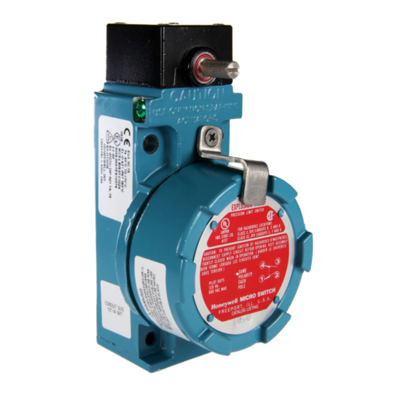
- Page 6 PK 80148 ISSUE 12 SPECIAL CONDITIONS FOR SAFE USE MOUNT, ADJUST, WIRE Honeywell explosion-proof switches are designed specifically MOUNTING for use in hazardous location applications. The BX enclosure is sealed for protection against corrosion, water, dust and oil as Note mounting dimension drawings for hole locations (Fig. 9, defined in IEC60529.
- Page 7 1,4 Nm to 1,8 Nm [12 in-lb to 16 in-lb]. to 16 in-lb]. FIGURE 4. FIGURE 5. FIGURE 7. FIGURE 8. NOTE: Pin position above indicates the direction of actuation. Honeywell Sensing and Control...
-
Page 8: Wiring Instructions
Use only non-sparking levers to retain the explosion proof quali- authorities permit or require such connections. (See ties. Figure 11) FIGURE 10. WIRING INSTRUCTIONS FIGURE 11. WIRING INSTRUCTIONS 1,5 Nm to 1,8 Nm [13.27 in-lb to 16 in-lb] tightening torque Honeywell Sensing and Control... - Page 9 MONTAJE, AJUSTE Y CABLEADO SEGURO MONTAJE Los interruptores Honeywell a prueba de explosiones están Observe los dibujos en perspectiva del montaje para observar la específicamente diseñados para su uso en lugares peligrosos. La ubicación de los orificios (fig. 9, página 3). La caja BX se puede caja BX está...
- Page 10 FIGURA 8. interruptor y ajuste bien los tornillos del cabezal con una torsión de 1,4 Nm a 1,8 Nm [12 in-lb a 16 in-lb]. FIGURA 4. FIGURA 5. NOTA: La posición del pasador que figura arriba indica la dirección de actuación. Honeywell Sensing and Control...
-
Page 11: Instrucciones De Cableado
(Vea la figura 11) FIGURA 10. INSTRUCCIONES DE CABLEADO FIGURA 11. INSTRUCCIONES DE CABLEADO Par de ajuste 1,5 Nm a 1,8 Nm [13,27 in-lb a 16 in-lb] Honeywell Sensing and Control... - Page 12 ISSUE 12 BESONDERE BEDINGUNGEN FÜR DIE BEFESTIGUNG, EINSTELLUNG, SICHERE VERWENDUNG VERDRAHTUNG Die explosionsgeschützten Schalter von Honeywell wurden BEFESTIGUNG speziell für die Verwendung in Gefahrenbereichsanwendungen entwickelt. Das BX-Gehäuse ist zum Schutz gegen Korrosion, Die Montagebohrungen sind in den Einbaumaßzeichnungen Wasser, Staub und Öl gemäß der Norm IEC60529 abgedichtet.
- Page 13 Setzen Sie den Betätigerkopf auf das Schaltergehäuse und ziehen Sie die Befestigungsschrauben am Kopf mit einem ABBILDUNG 7: ABBILDUNG 8: Anzugsmoment von 1,4 Nm bis 1,8 Nm [12 in-lb bis 16 in-lb] fest. ABBILDUNG 4: ABBILDUNG 5: HINWEIS: Die oben abgebildete Stiftposition zeigt die Betätigungsrichtung an. Honeywell Sensing and Control...
- Page 14 Erdungsverbindung gedacht, sofern lokale Gesetze oder Vorschriften einen solchen Anschluss erlauben oder fordern. (Siehe Abbildung 11.) ABBILDUNG 10: ANWEISUNGEN ZUR ABBILDUNG 11: ANWEISUNGEN ZUR VERDRAHTUNG VERDRAHTUNG 1,5 Nm bis 1,8 Nm [13.27 in-lb to 16 in-lb] Anzugsmoment Honeywell Sensing and Control...
- Page 15 MONTAGE, REGLAGE ET RACCORDEMENT UTILISATION SANS DANGER MONTAGE Les interrupteurs antidéflagrants de Honeywell ont été spécialement Reportez-vous aux schémas dimensionnels de montage pour loca- conçus pour une utilisation dans des applications dangereuses. liser les orifices (Fig. 9 page 3). Les interrupteurs de série BX sont L’enveloppe des interrupteurs de série BX est étanche afin d’of-...
- Page 16 1,4 à 1,8 Nm [12 à 16 lb-in]. FIGURE 7. FIGURE 8. FIGURE 4. FIGURE 5. REMARQUE : la position de la broche ci-dessus indique le sens de commutation. Honeywell Sensing and Control...
-
Page 17: Instructions De Raccordement
(voir la Figure 11). FIGURE 10. INSTRUCTIONS DE RACCORDEMENT FIGURE 11. INSTRUCTIONS DE RACCORDEMENT 1,5 à 1,8 Nm [13,27 à 16 in-lb] Couple de serrage Honeywell Sensing and Control... -
Page 18: Istruzioni Per La Regolazione
CONDIZIONI SPECIALI PER L'UTILIZZO SICURO cavità dell'interruttore e la testa e (2) le filettature di fissaggio del coperchio all'involucro sul lato anteriore dell'interruttore. Gli interruttori antideflagranti Honeywell sono progettati specifi- camente per l'uso in applicazioni in ambienti pericolosi. L'involu- MONTAGGIO, REGOLAZIONE, CABLAGGIO cro della serie BX è... - Page 19 Riposizionare la testa operativa sull'involucro dell'interruttore e di attuazione. serrare saldamente le viti della testa a una coppia compresa tra 1,4 Nm e 1,8 Nm [12 libbre per pollice e 16 libbre per pollice]. FIGURA 4. FIGURA 5. Honeywell Sensing and Control...
- Page 20 (Vedere figura 11) FIGURA 10. ISTRUZIONI PER IL CABLAGGIO FIGURA 11. ISTRUZIONI PER IL CABLAGGIO coppia di serraggio: da 1,5 Nm a 1,8 Nm [da 13,27 libbre per pollice a 16 libbre per pollice] Honeywell Sensing and Control...
- Page 21 MONTAGEM, AJUSTE, FIAÇÃO SEGURA MONTAGEM As chaves à prova de explosões Honeywell são designadas especificamente para uso em locais perigosos. O invólucro da Observe nos diagramas de dimensões de montagem as locali- série BX é vedado para proteção contra corrosão, água, poeira zações dos furos (Fig.
- Page 22 Substitua o cabeçote de operação no invólucro da chave e aperte os parafusos com torque de 1,4 Nm a 1,8 Nm FIGURA 7. FIGURA 8. [12 pol-lb a 16 pol-lb]. FIGURA 4. FIGURA 5. OBSERVAÇÃO: A posição do pino acima indica a direção de acionamento. Honeywell Sensing and Control...
- Page 23 (Consulte a Figura 11) FIGURA 10. INSTRUÇÕES DE FIAÇÃO FIGURA 11. INSTRUÇÕES DE FIAÇÃO 1,5 Nm a 1,8 Nm [13,27 pol-lb a 16 pol-lb] torque de aperto Honeywell Sensing and Control...
- Page 24 准:C22.2 No. 25-1966 和 C22.2 No. 30-M1986. 的要求。 对于户外环境和有防爆和密封要求的恶劣环境而言,BX 系列产品 是最理想的选择。为满足防爆要求,BX 系列产品的外壳内设置有 火焰通道,可以在爆炸气体到达外壳周围的易爆气体之前将它们冷 操作柄位置调整 却到燃点以下。BX 上的火焰通道包括:1)开关腔和开关头二者之 旋转式驱动单元上的操作柄可调整至转轴周围 360° 内的任意位置。 间的延长柱塞;2)开关前部的罩壳螺纹。 用 3.6 毫米(9/64 英寸)规格的六角扳手拧松带帽螺钉。 将操作柄调至所需位置。 安全地拧紧螺钉,直到不能用手移动薄垫片为止。 将螺钉再拧 1/8 至 1/4 圈以确保操作柄紧固在转轴上(图 2)。 调整工具包 LSZ4005 内提供了 3.6 毫米(9/64 英寸)规格的六角 扳手。 Honeywell Sensing and Control...
- Page 25 用螺丝刀或类似工具将凸轮旋转至所需的动作位置(图 6)。 将柱塞插脚插入选定的位置。 正向滑动凸轮至原位,盖上铰接外罩。 将工作头放回开关外壳上的原位置,将螺钉安全地紧固至工作 将工作头放回开关外壳上的原位置,将螺钉安全地紧固至工作 扭矩 1.4 Nm 至 1.8 Nm(12 in-lb 至 16 in-lb)。 扭矩 1.4 Nm 至 1.8 Nm(12 in-lb 至 16 in-lb)。 图 7. 图 8. 图 4. 图 5. 注意:上述的插脚位置 表示动作方向。 Honeywell Sensing and Control...
- Page 26 [90 in-lb]。 将外罩锁紧卡件置于圆形外罩上,紧固方头十字槽螺钉至工作 扭矩 1.5 Nm 至 1.8 Nm [13.27 in-lb 至 16 in-lb]。(见图 9 和 图 10) 内部接地端子必须用于设备接地连接,外部端子可用于补充性 焊接连接,但须在当地法规或权威部门许可或要求下进行。 (见图 11.) 更换操作柄 为保持产品的防爆特性,只能使用防爆操作柄。 图 10.接线说明 图 11.接线说明 1.8 Nm 1.5 Nm 16 in-lb] [13.27 in-lb Honeywell Sensing and Control...
- Page 27 (毫米/英寸) [3.00] [3.81] 所有开关型号均可选用规格为 1/2-14NPT、3/4-14NPT、M20、 PG13.5、PF1/2 的导线孔。 确保配套螺纹接口件与产品铭牌上显示的 导线螺纹相一致。 2X Ø 5,16 [0.203] 2X 5/16 UNC - 2B 38,10 MTG HOLES TAPPED FROM 25,40 [1.50] REAR ONLY [1.00] x 22,23 [0.875] min. 41,15 [1.62] 73,18 [2.88] Honeywell Sensing and Control...
- Page 28 [3.375] [4.75] Ø 76,20 96.77 [3.00] [3.81] 2X 5 / 16 - 2B UNC 2X Ø 5,16 [0.203] 38,10 TAPPED FROM MTG. HOLES [1.50] REAR ONLY 25,4 x 22,23 [0.875] min. [1.00] 41,15 [1.62] 73,18 [2.88] Honeywell Sensing and Control...
- Page 29 MICRO SWITCH™ BX Series PK 80148 ISSUE 12 Honeywell Sensing and Control...
- Page 30 Fall haftet Honeywell für mittelbare, indirekte oder Sonder- While we provide application assistance personally, through our schäden. literature and the Honeywell web site, it is up to the customer to determine the suitability of the product in the application. Specifi- Obwohl Honeywell persönliche und schriftliche Anwendungshilfe cations may change without notice.
- Page 31 GARANTIA/SOLUÇÕES 通过网站联系:sensing.honeywell.com A Honeywell garante seus produtos contra defeitos de material 电话和传真: e de fabricação. A garantia padrão de produto da Honeywell se +1-800-537-6945 美国/加拿大 aplica a menos que haja um acordo diferente por escrito com a +1-815-235-6847; +1-815-235-6545 传真...
Need help?
Do you have a question about the MICRO SWITCH BX Series and is the answer not in the manual?
Questions and answers