Advertisement
Available languages
Available languages
Applications
The PLS750C/PLS751C programmable wall switch has been designed to control lights and motors:
Load types
Lights and resistive loads
1800 W (15 A @ 120 V)
(except tungsten)
Tungsten lights
1440 W (12 A @ 120 V)
Motors
1 hp
Installation
Cut power at the circuit breaker to avoid electric shock.
Remove the existing switch. (For a 3-way installation, identify and label the wire that is connected to
the "common" screw.)
Install the new switch (see the appropriate section below).
Apply power at the circuit breaker.
SINGLE-SWITCH INSTALLATION
black
white
white
120
VAC
black
EXISTING 3-WAY INSTALLATION
black
blue (LOAD)
white
white (NEUTRAL)
black (LINE)
yellow (3-WAY)
Connect the LOAD wire on the PLS750C/PLS751C to the "common" wire, which you identified when
removing the old switch. Connect the NEUTRAL wire to the neutral (white) wires. Connect the LINE and 3-
WAY wires to the two remaining wires. At the other 3-way switch, connect the jumper wire between the
"common" screw and the screw where the LINE wire of the PLS750C/PLS751C is connected.
NOTE: If the timer screen does not turn on when you apply power at the circuit break (step 4), cut the power
at the circuit breaker again, switch the blue (LOAD) and the black (LINE) wires and reapply power.
NEW 3-WAY INSTALLATION
black
blue (LOAD)
white
white (NEUTRAL)
black (LINE)
yellow (3 WAY)
white
120
VAC
black
PLS750C/PLS751C
NOTE:
Maximum load
Examples
•
fluorescent lights
•
compact fluorescent lights (CFL)
•
electronic ballasts
•
sodium lamps
•
block heaters
•
incandescent lights
•
halogen lights
•
pool filter pumps
•
fans
blue (LOAD)
white (NEUTRAL)
yellow (3-WAY)
black (LINE)
120 VAC
white
black
red
black
white
white
black
This switch cannot be used if there is no neutral wire
(white wires joint together) inside the electrical box.
1.
Quick Start-up
Set the time and date before using the timer for the first time.
The switch will turn the lights on at sunset and turn them off at 11:00 pm by default. If these settings are
appropriate for you, you only need to set the time and date (see shaded zone in the menu flowchart sheet).
If the switch's sunset time does not correspond to the actual sunset time, see sections 5.3.3 and 5.3.4.
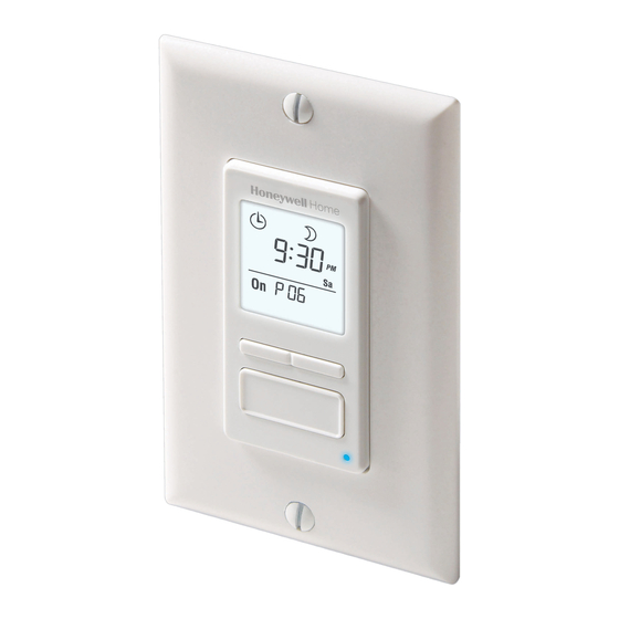
Operation
Indicates the mode of operation
(see Section 5.1)
Indicates the keypad is locked
(see Section 6)
2.
Indicates the time and day
Indicates the current program
Briefly press this button to turn the
lights on or off. See "Temporary
Override" in Section 5.1.4.
Press for 3 seconds to enter the
setup menus.
Setup Menus
Press the main button for 3 seconds to enter the setup menus. Refer to
the menu flowchart sheet on how to navigate the menus.
(3 sec.)
5.1
Mode Menu
You can use the Mode menu to select one of the three modes of operation (see sections 5.1.1 to 5.1.3).
5.1.1 Manual Mode
In Manual mode, the switch operates like a regular switch. To turn the lights on or off,
briefly press the main button. The
jumper
5.1.2 Automatic Mode
In Automatic mode, the switch turns the lights on or off according to the set programs (see
Section 5.4). The
icon as well as the current program number are displayed.
three-way
5.1.3 Random Mode
switch
In Random mode, the switch has no specific times to turn the lights on or off. This mode is
designed to give the impression the house is occupied during your absence. It is similar to the
Automatic mode except there is no fixed program. The programs are automatically set to different
times by the switch every day. The
The first "On" program occurs at sunset. Each "On" program lasts between 1 hour and 1
hour and 30 minutes; each "Off" program lasts between 15 and 30 minutes. The last "Off"
program occurs between 10:30 pm and midnight.
5.1.4 Temporary Override
When the switch is in Automatic or Random mode, you can press the main button at any time to override the
default state for the current program. The lights will turn off if they are on and vice versa. The icon (On or Off)
of the new state flashes to indicate that the state is temporary. The new state is maintained until you press
the main button again or till the next "On" or "Off" program.
5.2
Time Menu
The time display flashes on the screen when the time has not yet been set or after a 4-hour power outage.
Use the Time menu to select the time format (12-hour or 24-hour) and to set the clock and date.
single-pole
NOTE: The date is used to determine the sunset and sunrise times.
switch
PLS750C/PLS751C
7-day Solar Programmable Wall Switch
The
icon indicates the current
program has been activated at sunset.
The
icon indicates the current
program has been activated at sunrise.
Indicates the load on/off state
Press this button to display today's sunrise time.
Press this button to display today's sunset time.
The LED illuminates when the load
state is on.
icon appears when the switch is in Manual mode.
icon appears when the switch is in Random mode.
User guide
3.
4.
5.
1/8
Advertisement
Table of Contents

Related Manuals for Honeywell PLS750C


Summary of Contents for Honeywell PLS750C
- Page 1 It is similar to the Connect the LOAD wire on the PLS750C/PLS751C to the “common” wire, which you identified when Automatic mode except there is no fixed program. The programs are automatically set to different removing the old switch.
-
Page 2: Configuration Menu
For example, if the shall not apply if it is shown by Honeywell that the defect or malfunction was lights are off, they will turn on when you press the main button. - Page 3 Ce mode sert à donner l’impression que votre résidence est occupée pendant Relier le fil « LOAD » du PLS750C/PLS751C au fil « commun » identifié lorsque vous avez enlevé l’ancien votre absence. Il est semblable au mode Automatique, sauf qu’il n’y a pas de programme interrupteur.
- Page 4 7 jours P01 Off dimanche (Su) Honeywell garantit ce produit, à l'exception des piles, contre tout vice de fabrication ou de Menu Programme (Prog) matière dans la mesure où il en est fait une utilisation et un entretien convenables, et ce,...
- Page 5 5.1.3 Modo Aleatorio blanco Conectar el cable “LOAD” del PLS750C/PLS751C al cable “común”, identificado cuando se retiró el antiguo En modo Aleatorio, el interruptor está programado para encender y apagar las luces interruptor. Conectar el cable “GND” al terminal de puesta a tierra en la caja de electricidad. Conectar los arbitrariamente y no en un momento preciso.
- Page 6 En ese caso, es necesario ingresar un factor de corrección (+1 o -1 hora, referirse al suplemento). Si no, dejarlo en 0 (valor por Honeywell garantiza por un período de tres (3) años, a partir de la fecha de P03 On ninguno —...
- Page 7 PLS750C/PLS751C Menu flowchart Organigramme des menus Organigrama de los menus Flowchart shows default settings Legend / Legende / Leyenda Le diagramme contient les réglages par défaut. El diagrama contiene los ajustes por defecto. Briefly press this button to go to preceding menu or setting.
- Page 8 SHREVEPORT WINDSOR JACKSONVILLE SOUTH BEND REPÚBLICA DOMINICANA WINNIPEG KANSAS CITY SPOKANE -117 Ciudad Lat. Long. Adj. KNOXVILLE YELLOWKNIFE -114 SPRINGFIELD (IL) SANTO DOMINGO LAKEWOOD -105 SPRINGFIELD (MA) PLS750C/PLS751C Printed in USA / Imprimé aux É.-U. / Impreso en EE.UU. 07-2011...
Need help?
Do you have a question about the PLS750C and is the answer not in the manual?
Questions and answers