
Related Manuals for FTS LT1


Summary of Contents for FTS LT1
- Page 1 EXTREME ENVIRONMENTS. EXTREMELY RELIABLE. LT1 SYSTEM Installation and Quick Start Guide For use with LT1-CELL /LT1-CELL-VZ/LT1–GOES 1.800.548.4264 | www.ftsinc.com 700-LT1-SYS-IG Rev2 22 Oct 2018 Part #19795...
- Page 2 Contact Information Canadian Headquarters: 1065 Henry Eng Place Victoria, BC | V9B 6B2 | Canada www.ftsinc.com Toll-free: 1.800.548.4264 Local: 250.478.5561 Technical support portal: http://support.ftsinc.com Email: service@ftsinc.com...
-
Page 3: Table Of Contents
SYSTEM COMPONENTS ..........................1 POLE MOUNT ............................. 3 REQUIRED TOOLS AND EQUIPMENT ....................... 3 CHAPTER 2 SETTING UP AN LT1 STATION ............4 PRIOR TO PROCEEDING TO THE FIELD....................4 SITE SELECTION ............................4 MOUNTING THE ENCLOSURE........................5 MOUNTING THE SOLAR PANEL ........................ 5 GROUNDING THE SYSTEM ........................ -
Page 4: Chapter 1 Description
Chapter 1 DESCRIPTION 1.1 GENERAL This guide is meant as a ready reference to set up an LT1 System. Details of all aspects of station operation can be found on the FTS Support website (http://support.ftsinc.com/) in the following manuals: • LT1 (Cell/GOES) Operator’s Manual (700-LT1-Man) •... - Page 5 19465 • LT1 Ground Cable 1(attached in enclosure) 19484 • LT1 Ground Cable 2 (attached outside of enclosure) • 2 x LT1 Pole Mount Brackets with mounting hardware 19480 11597 • 2 x U-Bolts with mounting hardware 19930 (GOES only) •...
-
Page 6: Pole Mount
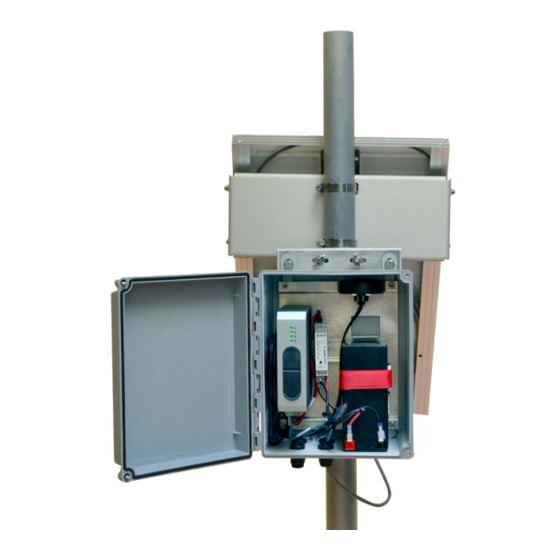
19467 19472 1.3 POLE MOUNT The LT1 System comes with fittings so that it can be mounted on a secure vertical pole with a 2” outer diameter. FTS recommends a 1.5”nominal (1.9” outer diameter) schedule 40 or 80 aluminum pipe. -
Page 7: Chapter 2 Setting Up An Lt1 Station
Ensure any SDI-12 sensors to be added in the field exist in the sensor library Bring the required tools (see section 1.4) * Details of testing the LT1 are found in the LT1 User’s Manual (700-LT1-Man) 2.2 SITE SELECTION... -
Page 8: Mounting The Enclosure
Consider sun position and length of shadows in all seasons. Even a small shadow cast by a guy line or small branch can affect the efficiency of the solar panel. 700- LT1-SYS-IG Rev 2 22 Oct 2018... -
Page 9: Grounding The System
FTS recommends that you consult a qualified professional to ensure adequate earth ground protection is installed for the site and that all local regulations are met. Set up the earth-ground system and secure the free eye of the LT1 Ground Cable 2 to the grounding system. 700- LT1-SYS-IG... -
Page 10: Insert Cables
Replace the gland cap, ensuring it is tightly screwed on to form a seal. For LT1-GOES systems, the fitted gland on the SMA to N cable for the satellite antenna and the SMA to SMA jack cable (if using an externally mounted GPS antenna) replaces the enclosure gland. -
Page 11: Telemetry
SDI-12 sensors. Additionally, if more than two devices are being connected, a ground terminal will have to be shared. Once sensors are connected to the 8 pin terminal block it can be inserted into the LT1. 700- LT1-SYS-IG... - Page 12 3 A must be attached to both the PW and HT pins. Details of connecting an FT7X2 RS-485 wind sensor are found in App Note 162 (700-AN-162) and posted to the FTS Support site. Figure 2-5: 8 Pin Terminal Block Wiring Guide...
-
Page 13: Power Connections
2.9 POWER CONNECTIONS The LT1 SYSTEM is powered through a battery which maintains its charge through a solar panel and regulator. Refer to the following diagram for pin locations when connecting devices to the solar regulator. IMPORTANT! Power connections must be made in... - Page 14 Black wire (-) to terminal 7 (GND) To battery Red wire (+) to terminal 9 (BAT) 5) Mount the solar regulator onto the DIN rail beside the the LT1 and secure the battery in position using the red Velcro strap. Release...
- Page 15 4) Insert the terminal block into the LT1. 5) Turn on the regulator output by quickly pressing the black button on the regulator. Ensure the Output LED on the solar regulator turns solid On and the LT1 LEDs indicate there is power.
-
Page 16: Led Status Indicators
2.10 LED STATUS INDICATORS Once power is supplied, the LT1 will boot up, and establish a GPS fix. The green LEDs indicate the status of the system. 2.10.1 START UP When power is first supplied or someone connects to the station:... -
Page 17: Solar Regulator Status Leds
Solar panel connected Battery ready Output turned on Output disabled Off– blinks on every 2s (can be turned on) Battery charging On-blinks off every 2s Battery discharging Off-blinks on every 2s 700- LT1-SYS-IG Rev 2 22 Oct 2018 Page 14/22... -
Page 18: Chapter 3 Configuring With The Fts360 Config App
Detailed information on FTS360 and the FTS360 Config App can be found in the FTS360 User Manual (700-FTS360-Man) 3.1 CONFIGURING SENSORS Once connected to the LT1 and powered, use the FTS360 Config App to add and configure the sensor for the station. 1) Connect to Station •... - Page 19 GPS fix This will indicate GOES or Cellular as per the LT1 type 2). Add and configure sensors: Select the sensor type to add (NMEA or Rain). To add an SDI-12 sensor, select the Add Sensor bar.
-
Page 20: Configure Goes/Eumetsat Station Settings/Message
Transmission Enabled button will be displayed 2) To configure the message, select the Configure Transmitted Message bar and use the drop down menu to select the data format type. 700- LT1-SYS-IG Rev 2 22 Oct 2018 Page 17/22... -
Page 21: Synchronize And Disconnect
FTS360. If you are not in an area where you can access the Internet to perform a data sync before leaving the site, as soon as you have internet access you should open the FTS360 Config App to sync the configuration back to the FTS360. 700- LT1-SYS-IG Rev 2 22 Oct 2018 Page 18/22... - Page 22 2). Disconnect: Select the “Disconnect” button on the FTS360 Config App screen If you move out of range of the LT1, it will automatically disconnect. Any changes made that were not saved before an inadvertent disconnection will have to be repeated and saved.
-
Page 23: Appendix Atroubleshooting
Battery fully 2) If being used with a solar panel and regulator, discharged check connections to ensure battery being charged Power off the LT1. Insert SD card or confirm inserted SD card not SD card is properly seated and locked. - Page 24 Fault attempting 2) If no BLE status light after trying (1), contact FTS Support to connect 1) If you belong to more than one agency: You are signed into i) Access the internet and log into FTS360 in the station’s...
-
Page 25: Document Revision History
DOCUMENT REVISION HISTORY Revision Date Description Combined Cellular and GOES installation information. 7 May 2018 Supersedes 700-LT1-CELL-IG Corrected part # for 22 Oct 2018 Slot screwdriver 700- LT1-SYS-IG Rev 2 22 Oct 2018 Page 22/22...
Need help?
Do you have a question about the LT1 and is the answer not in the manual?
Questions and answers