
Related Manuals for FTS LX-80-8


Summary of Contents for FTS LX-80-8
- Page 1 EXTREME ENVIRONMENTS. EXTREMELY RELIABLE. NON-CONTACT LEVEL METER Continuous Level Measurement Operating Manual 1.800.548.4264 | www.ftsinc.com 700-SDI-RADAR-LX-80-Man Rev 1 08 Oct 2021...
- Page 2 Contact Information Canadian Headquarters: 1065 Henry Eng Place Victoria, BC | V9B 6B2 | Canada www.ftsinc.com Toll-free: 1.800.548.4264 Local: 250.478.5561 Technical support portal: http://support.ftsinc.com Email: service@ftsinc.com...
-
Page 3: Table Of Contents
Contents APPROPRIATE USE ............................. 1 GENERAL SAFETY INSTRUCTIONS ......................1 CHANGING UNITS ............................2 RADAR CALIBRATION ..........................3 FUNCTIONAL PRINCIPLE ........................... 3 2.3.1 MEASUREMENT THROUGH CONTAINERS ..................3 2.3.2 RAIN AND WIND ..........................4 2.3.3 INTERFERENCE AND MULTIPLE RADARS ..................4 2.3.4 FOGGING AND EVAPORATION ...................... - Page 4 5.2.3 IIR (INFINITE IMPULSE RESPONSE) CONSTANT ................16 5.2.4 AMPLITUDE THRESHOLD ....................... 16 5.2.5 PEAK DETECTOR TYPE ........................16 MEASUREMENT PARAMETERS ........................ 16 5.3.1 LEVEL UNIT ............................16 5.3.2 LEVEL OFFSET ..........................16 5.3.3 ACTIVE ZONE PARAMETERS ......................17 5.3.4 SENSOR HEIGHT ..........................
- Page 5 10.1 SPECIFICATIONS ............................47 10.2 MECHANICAL ASSEMBLY ........................48...
-
Page 6: Appropriate Use
SAFETY 1.1 APPROPRIATE USE Operational reliability is ensured only if the instrument is properly used according to the specifications in this manual as well as possible supplementary instructions. WARNING: Inappropriate or incorrect use of the instrument can give rise to application specific hazards, e.g., damage to system components through incorrect mounting or adjustment. -
Page 7: Changing Units
It comes in three versions: 8 meter, 15 meter and 30 meter each with a 10m cable . Measurement frequency is 1 Hz. FTS Part # Model Maximum Detection Accuracy... -
Page 8: Radar Calibration
2.2 RADAR CALIBRATION The level meter is able to perform self-calibration which calibrates the radar transceiver electronics. Each instrument is calibrated in the factory, and the factory calibration parameters are stored in the device. Typically, there is no need to repeat self-calibration, even after using the level meter over several years. -
Page 9: Rain And Wind
2.3.2 RAIN AND WIND The LX-80’s integrated internal software filters out effects of rain, fog and wind. However, these filters have some limitations. The majority of measurement inaccuracies caused by environmental factors can be solved by proper sensor installation (see Chapter 4). Rain and snow fall reduce the reflectivity of the water surface thus reducing the SNR . -
Page 10: Relative Measurement
Depending on the surface roughness, the incident angle ratio between power reflected away from the radar and towards the radar can significantly vary. To maximize reflected power back to the radar, the radar should be mounted so that the angle of the transmitted radar beam to the water is 90°. - Page 11 For example: the sensor is mounted at an unknown height above the riverbed and using staff gauge it is determined that the water level at that given time is 1.34m. The sensor detects water at the distance of 6.02m. By setting the value 1.34m as the staff gauge measurement at the same time when the device measures the distance as 6.02m, sensor height will be calculated as the sum of the two values: 6.02m + 1.34m = 7.36m...
-
Page 12: Connector Pin-Out And Wiring
ELECTRICAL CONNECTIONS 3.1 CONNECTOR PIN-OUT AND WIRING The LX-80 sensor is supplied with a robust IP68 M12 connector and cable. The connector and cable details are shown on Figure 3-1. The user is responsible for connecting the sensor to the data collection platform using the flying leads. -
Page 13: Sdi-12 Interface
3.2 SDI-12 INTERFACE SDI-12 interface is widely used to connect hydrological equipment to dataloggers. SDI-12 uses a single communication line, and very slow speed communication to enable the use of very long communication cables. For hydrological applications, SDI-12 communication interface is a valid option and the instrument is natively able to communicate directly with SDI-12 master devices (dataloggers etc.). - Page 14 loggers, or data concentrators. The signal range and function for 4 – 20 mA analog output can be configured in the setup application so the sensor will be able to signal the best suitable value range with the available current range. The sensor’s current step has a limiting resolution of 0.3 μA.
-
Page 15: Site Selection
INSTALLATION 4.1 SITE SELECTION For best results, the water’s surface being measured should be calm, clean of vegetation, rocks, sand deposits or other obstacles. Additionally, the mounting location of the radar sensor should provide an unobstructed line to the measured surface. Any close object in the vicinity of the sensor can reduce accuracy and introduce offsets in measurements. -
Page 16: Installation Position
4.2 INSTALLATION POSITION The level meter must be installed above the water surface at a 90° angle pointing directly towards the water surface and at a height within the range specified in Table 4-2. Ideally the tilt angle should be 0° along both the X and Y axes for a 90⁰ angle between the radar beam and the water surface. However, the unit can tolerate up to ±2⁰... -
Page 17: Communication Interfaces
RADAR PARAMETERS The following radar parameters can be configured by connecting the radar to a PC and using the Instrument Configurator (refer to Chapter 8). Additionally, if using SDI-12 protocols, configuration can be done through a datalogger and using the SDI-12 commands outlined in Chapter 12. 1) Communication interfaces 2) Processing parameters 3) Measurement Parameters... -
Page 18: Modbus Parity
Modbus ID: Configures the device (slave) ID to be used for Modbus RTU protocol. Modbus RTU uses request/response format and allows multiple instruments to be connected on the same bus. When a remote master transmits the request message, it will use the device ID as a device address. -
Page 19: Ma Parameters
Stop bits are added to the end of each data byte transferred over serial communication to allow a pause between two bytes. One or two bits may be used. The default setting on most Modbus RTU devices is one stop bit, but some dataloggers may require that the instrument is configured to use two stop bits. -
Page 20: Filter Length
IIR (Infinite Impulse Response): This filter is used to smooth the data. When compared to a moving average filter, the IIR filter reacts more quickly to initial changes in the data, but it takes longer for the smoothed value to reach the new measurement. The use of the IIR filter is discouraged for general applications. -
Page 21: Iir (Infinite Impulse Response) Constant
5.2.3 IIR (INFINITE IMPULSE RESPONSE) CONSTANT Figure 5-7: IIR Constant The constant used by the infinite impulse response (IIR) filter. Accepted values are decimal numbers between 0 and 1. When the IIR constant value is closer to 0.0, the filter response will be slower. When the IIR constant value is closer to 1.0, the filter response will be faster. -
Page 22: Active Zone Parameters
5.3.3 ACTIVE ZONE PARAMETERS Figure 5-8: Active Zone Parameters This parameter limits the operational range of the instrument. The instrument will detect water level only within the range set by the Active Zone Minimum and Active Zone Maximum parameters. This parameter is the best way to filter unwanted radar reflections from other structures and objects that could cause false instrument readings. -
Page 23: Staff Gauge
Example: If the instrument is mounted exactly 5 metres above the gauge zero level, then this parameter should be set to 5 m. Then, if the instrument measures the distance between the instrument and the water as 4 m, it will report that the water level is 1 m, because the water is 1 m above the gauge-zero level. -
Page 24: Power Management
5.3.7 POWER MANAGEMENT There are two power modes: Continuous scanning and SDI-12. Power consumption can be reduced by operating in SDI-12 mode Continuous Mode: In continuous mode the device constantly performs measurements, which are transmitted over the RS-232 interface and made available over Modbus and SDI-12 interfaces. -
Page 25: Serial Rs-232 Interface
DATA INTERFACES The LX-80 level meter offers multiple data interfaces, for ease of integration with existing SCADA/telemetry systems. 6.1 SERIAL RS-232 INTERFACE The Serial RS-232 interface is used for direct connection of a single level meter unit with the computer. The serial interface is used both for retrieving live level measurements and for configuration of the level meter device. -
Page 26: Sdi-12 Protocol
DATA PROTOCOLS The LX-80 level meter supports the following data protocols: 1) SDI-12 protocol over SDI-12 interface 2) NMEA-like protocol on RS-232 interface that constantly outputs the detected current level and averaged level, depending on the active settings for data filtering 3) Servicing protocol on RS-232 interface for configuring the unit 4) Request-response protocol (Modbus) on RS-485 interface that allows multiple units to be used on a single RS-485 bus... -
Page 27: Commands
COMMAND(S) RESULTS ammm8 aMC! mmm = number of seconds before measurements will be ready 8 = number of values that will be returned aCC! aDO! a+f+f+d+d+d+d+f+f +f – measured relative level depending on sensor height +f – measured distance from sensor to water +d –... - Page 28 X COMMAND DEFINITION RESPONSE AND DETAILS Response: a+f Get minimum aXGDZ0! In which “f” =the active zone minimum value. active zone value Sensor will not report a measurement lower than this value. Set minimum Replace “f” with desired minimum active zone value. aXGDZ0+f! active zone value Sensor will not report a measurement lower than this value.
- Page 29 X COMMAND DEFINITION RESPONSE AND DETAILS Response: a+t In which “t” = the peak detector type: 0 – report the distance to the maximum peak which Get peak detector xGPDT! type corresponds to the maximum radar signal reflection 1 - report the last peak which corresponds to the furthest reflection from the radar;...
-
Page 30: Nmea Protocol (Rs-232)
7.2 NMEA PROTOCOL (RS-232) NMEA protocol is based on the standard protocol family widely used by navigation equipment. NMEA protocol is sentence oriented and can send multiple sentences with different information. The sentence content is designated by the starting keyword which is different for each sentence type. -
Page 31: Tilt Angle Report
The standard deviation of water level measurements. The number of samples used to calculate the standard deviation is equal to the configured filter length. This parameter is available on units with firmware versions greater than 2.3.2. 7.2.2 TILT ANGLE REPORT $ANG,A1,A2 <CR><LF>... - Page 32 second. The available values are standardised. Using higher baud rate over longer lines may introduce errors in transferred data. The default instrument RS-485 baud rate is 9600 bps. #set_modbus_baud_rate=9600 #set_modbus_baud_rate=38400 #set_modbus_baud_rate=57600 #set_modbus_baud_rate=115200 #set_modbus_baud_rate=1200 #set_modbus_baud_rate=19200 Modbus ID: Configures the device (slave) ID to be used for Modbus RTU protocol. Modbus RTU uses request/response format and allows multiple instruments to be connected on the same bus.
-
Page 33: Change Processing Parameters
700 mm to 5000 mm, it is recommended to configure the minimum value to slightly below 700 mm (for example 500 mm). Alternatively, if the resolution is not critical, then minimum value for 4-20 mA output can be left to the instrument minimum of 0 mm. #set_analog_min=<value>... -
Page 34: Change Processing Parameters
Filter length - The length of the averaging filter, in number of readings, to smooth the measured values. The instrument performs 1 reading per second, so a filter length value of 10 will result in 10 seconds integration time. When using longer filter lengths, more measured values are used for filtering, and the resulting data will be smoother. - Page 35 detected, the sensor will report distance equal to 0. The threshold is used to filter noise and false readings and it is recommended to keep this value in the range 0 to 1000. #set_amplitude_threshold=<value> Active zone min. - This parameter limits the operational range of the instrument. The instrument will detect water level only within the range set by the Active zone min.
- Page 36 #set_power_save=0 (Operating mode) #set_power_save=1 (Standby mode) Power management - Switches the device between continuous scanning mode and SDI- 12 mode. In continuous mode the device constantly makes the measurements which are transmitted over the RS-232 interface and made available over Modbus and SDI-12 interfaces. The device is always available over RS-232 and Modbus interfaces.
-
Page 37: Modbus Protocol (Rs-485)
7.4 MODBUS PROTOCOL (RS-485) The unit responds to Modbus requests over RS-485 data line. The baud rate is configured through the PC application, and 1 stop bit, even parity, 8 data bits configuration is used. Modbus registers that are accessed by Modbus protocol are 16-bit (2-byte) registers. Any number of registers can be read or written over Modbus. -
Page 38: Retrieving Data From The Sensor
Slave Response Example 7.4.3 RETRIEVING DATA FROM THE SENSOR The following table defines the data returned by the instrument when the master requests that the register is read. Rows highlighted in blue denote the important values measured by the sensor. Rows highlighted in green denote operating parameters that could be changed in the field. - Page 39 700-SDI-RADAR-LX-80-Man Rev 1 08 Oct 2021 34/49...
-
Page 40: Writing To The Device's Configuration
7.4.4 WRITING TO THE DEVICE’S CONFIGURATION The following table defines how to write the device configuration. Rows highlighted in blue denote the important values measured by the sensor. Rows highlighted in green denote operating parameters that could be changed in the field. “Fun” corresponds to Modbus function codes, i.e. 0X05 –... - Page 41 700-SDI-RADAR-LX-80-Man Rev 1 08 Oct 2021 36/49...
- Page 42 700-SDI-RADAR-LX-80-Man Rev 1 08 Oct 2021 37/49...
-
Page 43: Connecting The Radar To The Configurator
INSTRUMENT CONFIGURATOR The Instrument Configurator is a user-friendly PC application which can be used for setting up the level meter operating parameters. Additionally, the Instrument Configurator displays current level measurements. The Instrument Configurator can be downloaded here under SOFTWARE: https://www.geolux-radars.com/lx-80.html 8.1 CONNECTING THE RADAR TO THE CONFIGURATOR Open the Instrument Configurator on your PC. -
Page 44: Configurator Functions
8.2 CONFIGURATOR FUNCTIONS A detailed description of the displayed parameters is available when hovering the mouse over the icon of a specific parameter. Initially, only the most important parameters are displayed while the rest are hidden. By clicking on the button with arrows next to the displayed parameters, the user can view all the data received from the device. -
Page 45: Echo Curve
A detailed description of the selected setting appears on the right side of the window when the user clicks on, or begins to change, a specific setting. When a setting is changed, the Set button will appear next to the setting. By clicking the Set button, the user confirms the change and the new setting is saved. - Page 46 TROUBLESHOOTING 700-SDI-RADAR-LX-80-Man Rev 1 08 Oct 2021 41/49...
- Page 47 (continued) 700-SDI-RADAR-LX-80-Man Rev 1 08 Oct 2021 42/49...
- Page 48 (continued) 700-SDI-RADAR-LX-80-Man Rev 1 08 Oct 2021 43/49...
- Page 49 700-SDI-RADAR-LX-80-Man Rev 1 08 Oct 2021 44/49...
- Page 50 700-SDI-RADAR-LX-80-Man Rev 1 08 Oct 2021 45/49...
- Page 51 700-SDI-RADAR-LX-80-Man Rev 1 08 Oct 2021 46/49...
- Page 52 1 sample per second - Increased sensitivity (optional) 10 samples per second Beam Angle (3dB) 5⁰ both axes (±2.5 ⁰each side) Measurement Range LX-80-8 0.1m – 8m (0.32ft – 26.2ft) • LX-80-15 0.1m – 15m (0.32ft – 49.2ft) • LX-80-30 •...
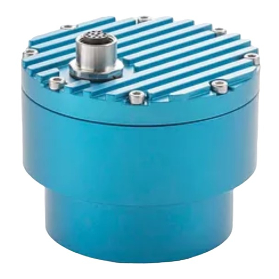
- Page 53 10.2 MECHANICAL ASSEMBLY All measurements in mm. 700-SDI-RADAR-LX-80-Man Rev 1 08 Oct 2021 48/49...
- Page 54 DOCUMENT REVISION HISTORY Revision Date Description 09 Oct 2021 Original. PM-287. 700-SDI-RADAR-LX-80-Man Rev 1 08 Oct 2021 49/49...
Need help?
Do you have a question about the LX-80-8 and is the answer not in the manual?
Questions and answers