Table of Contents
Advertisement
Quick Links
This guide is meant as a ready reference to set up an LT1 station in
the field. Details of station setup can be found on the FTS Support
website (http://support.ftsinc.com/) in the following manuals:
•
LT1 Operator's Manual (700-LT1- Man).
•
FTS360 and FTS360 Config App User Manual (700-FTS360- Man)
IMPORTANT!
Prior to proceeding to the field the
following MUST be completed
THE FTS 360 ADMINISTRATOR MUST:
Initialize (
) or login to FTS360
https://360.ftsinc.com/signup
Create a Technician account for the field technician
Ensure any SDI-12 sensors to be added in the field exist in
the sensor library (either default or custom sensor)
THE FIELD TECHNICIAN MUST:
Be invited to join FTS360 by administrator
Download the FTS360 Config App onto the device that will be
used in the field (iOS, Android or Windows)
CELL only: Provision the SIM card and test the LT1.
Ensure the APN for the SIM card is entered (Go to the FTS
Config App's dashboard and select "Cellular")
GOES: Bring satellite assignment information ( NESDIS ID,
channel, baud rate, transmission time)
Log onto the FTS360 Config App, synchronize with FTS360
(section B step 4). DO NOT LOG OUT
Ensure the SD Card is inserted.
Ensure any SDI-12 sensors to be added in the field exist in
the sensor library
1 - Refer to the LT1 Operator's Manual (700-LT1 Man) for details on testing the LT1
2 –Download at
Cellular APNs
Bell APN (Canada): wrmstatic.bell.ca.ioe
FTS
Verizon APN (USA): we01.vzwstatic
provided SIM
Rogers (Canada/USA): m2minternet.apn
Bell International (International): wrstat.bell.ca
SIM:_______________________________________
Customer Provided
700-LT1-QS Rev. 4 09 Feb 2021
Part #: 19682
LT1 PARTS
Terminal Blocks
• Data
• Power
Cell/Satellite
GPS
Also included:
• FTS approved industrial 4G SD card (inserted)
• 3/32" (2.4mm) slot screw driver
• GPS/Cellular antenna (CELL only)
• GPS antenna for LT1-GOES (if LT1-GOES-GPS-BNDL ordered)
• SMA male to N female adaptor (GOES only)
2
Optional Items:
.
• Activated SIM card (inserted) if FTS cellular plan purchased
•
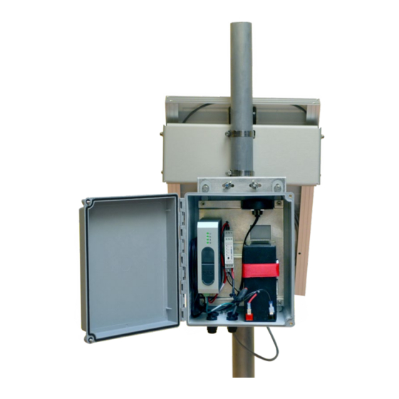
A. INSTALLING THE LT1
1. You will need:
•
Combined GPS/cellular antenna or GPS and satellite antennas
•
Antenna mounts (GPS/Cellular/Satellite
•
Weatherproof (IP66) enclosure with 35mm x 7.5mm DIN rail
and grounding lug
•
12VDC sealed lead acid battery
Earth-ground system
•
16 AWG - 28 AWG copper wire (for earth-ground system)
•
2 spools 16-28 AWG wire (for positive and negative power
•
connections)
Wire cutters and strippers
•
Tools/hardware to mount enclosure and antenna
•
Service and support:
FOR ALL LT1 CELLULAR AND SATELLITE VARIANTS
Status
Indicators
Port Access
• SD card
SIM Card
• Micro-B USB
Port Access
(Cell only)
http://support.ftsinc.com
Toll free: 1-800-548-4264
LT1 FIELD QUICK START GUIDE
2. Connect telemetry
a) Mount the antenna(s) in the desired position
b) Connect the antenna leads to their respective connectors on
the LT1 (use SMA to N adapter as required)
3. Mount the LT1
IMPORTANT!
The LT1 MUST be mounted in a weatherproof
Exposure to rain greater than 1mm per hour or
enclosure.
spray may cause the unit to fail.
Mount the LT1 onto the 35mm x 7.5mm DIN rail
•
4. Ground the system
FTS recommends that you consult a qualified professional to ensure
adequate earth ground protection is installed for the site and that all
local regulations and requirements are met
Connect a 16 to 28 AWG wire to the CG pin and attach the running
end to the enclosure's grounding lug. Complete the earth
ground system in accordance with its design.
CG
Chassis Ground
G
Power Ground
HT
High Current Power In
(for use with FT742 heated anemometer)
PW
Positive
5. Connect power
IMPORTANT!
If using a solar panel and regulator, follow the
manufacturer's directions to prevent system damage.
Direct to Battery: Follow the connection sequence to prevent
damage to the system.
1/2
Advertisement
Table of Contents

Related Manuals for FTS LT1


Summary of Contents for FTS LT1
- Page 1 5. Connect power • 12VDC sealed lead acid battery 1 - Refer to the LT1 Operator’s Manual (700-LT1 Man) for details on testing the LT1 Earth-ground system • 2 –Download at IMPORTANT! If using a solar panel and regulator, follow the 16 AWG - 28 AWG copper wire (for earth-ground system) •...
- Page 2 Note that three minutes after disconnecting from FTS360 Config App • Select Add an Alert Condition (FCA), the LT1 will enter low power mode. All lights will be off except • Use the drop-down menus to define the condition, the Data System Status which will blink once every 10 seconds.
Need help?
Do you have a question about the LT1 and is the answer not in the manual?
Questions and answers