Table of Contents
Advertisement
Quick Links
ThermoJet
TM
Air Forcing System
Operator's Manual
FTS
3538 Main Street
Stone Ridge NY 12484
(800) 824-0400 or (845) 687-0071
Fax: (845) 687-7481
info@ftssystems.com
www.SPindustries.com
SP Service
(877) 548-4666 or (845) 687-5400
Fax: (845) 687-0024
service@spindustries.com
Document # 200-31974-999 Rev. 009
Advertisement
Table of Contents

Related Manuals for FTS ThermoJet THJ80


Summary of Contents for FTS ThermoJet THJ80
- Page 1 ThermoJet Air Forcing System Operator’s Manual FTS 3538 Main Street Stone Ridge NY 12484 (800) 824-0400 or (845) 687-0071 Fax: (845) 687-7481 info@ftssystems.com www.SPindustries.com SP Service (877) 548-4666 or (845) 687-5400 Fax: (845) 687-0024 service@spindustries.com Document # 200-31974-999 Rev. 009...
- Page 2 Notice This Operation Manual contains confidential and proprietary information of SP Industries, Inc. and may be used only by a recipient designated by and for purposes specified by SP Industries, Inc. Reproduction of, dissemination of, modifications to, or the creation of derivative works from this manual, by any means and in any form or manner, is expressly prohibited, except with the prior written permission of SP Industries, Inc.
-
Page 3: Table Of Contents
Contents Contents ..............................iii Important Symbols..........................5 Introduction ............................. 7 Manual Introduction............................7 System Description ............................7 Description of Equipment ...........................8 System Features ..............................9 System Specifications ............................9 System Options and Accessories........................9 Installation............................. 12 Unpacking Information .............................12 Installation Planning ............................13 System Operation ..........................15 Assembly Instructions ............................15 Interconnections...............................15 RS232 Communication ............................17... - Page 4 Table of Figures Figure 1 – Common Test Fixture..........................8 Figure 2 - Accessories ............................11 Figure 3 – THJ80 ThermoJet w/ Motorized Arm option..................15 Figure 4 – Rear Panel Connections ........................16 Figure 5 – Improper Start-Up Screen ........................21 Figure 6 – Nozzle Limit Temperature Calibration NLTC Pop Up Screen ..............22 Figure 7 –...
-
Page 5: Important Symbols
Important Symbols FTS designs and manufactures units to be safe and reliable systems. Safety features are incorporated throughout and appropriate signs and symbols are provided. In this manual, safety issues are addressed in context. Users are strongly encouraged to become familiar with these symbols. - Page 6 {BLANK PAGE} © SP Industries, Inc. 200-31974-999 Rev. 009...
-
Page 7: Introduction
In the event the ThermoJet needs repair, please contact your local FTS representative, or call the SP Service Department. FTS reserves the right to improve the design, quality, and performance of all its products without notice. -
Page 8: Description Of Equipment
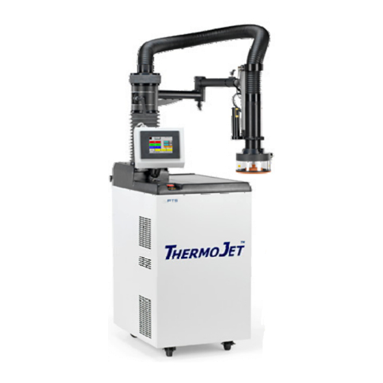
ThermoJet can be adapted to test circuit boards and a wide range of electronic assembly shapes and sizes. A broad range of standard and custom enclosures are offered by FTS for this purpose. 1. To ThermoJet Air Delivery Assembly 2. -
Page 9: System Features
See page 18 for instructions on operation of the motorized arm option. The system PLC controls all aspects of the temperature testing. FTS designed the control algorithms and features specifically for the THJ80 to provide an easy-to-learn, user-friendly operating environment through the touch screen while still providing the flexibility of remote access and data logging. - Page 10 Operator’s Manual: ThermoJet Chapter 1: Introduction ThermoJet Accessories ™ Part Number Description PE-2253 Display cable, 10 ft TJ-SHP-35 Thermal cap, phenolic, 3.5" ID x 2" deep. Includes one SSK235 TJ-SHP-45 Thermal cap, phenolic, 4.5" ID x 2" deep. Includes one SSK245 TJ-SHP-55 Thermal cap, phenolic, 5.5"...
-
Page 11: Figure 2 - Accessories
Standard shrouds are available in several different sized cylindrical and rectangular shapes to accommodate larger DUTs, circuit boards, or assemblies. Additionally, FTS in-house design and manufacturing capability can tailor shrouds to a customer’s specific application. We will be glad to provide a quotation for a custom-built shroud to fit your exact requirements. -
Page 12: Installation
Do not pull or put any stress on the flexible air delivery assembly. It is recommended that all packaging material be retained in case it is necessary to return the item to FTS for any reason. NOTE: Notify the motor freight carrier immediately of any damage. -
Page 13: Installation Planning
50% relative humidity. The THJ80 will, however, operate over a wide variety of ambient conditions without damage. Customers with unusual or severe ambient conditions should contact FTS for advice before operating their system. The control touch screen can be located on the top of the base unit (attached to the hose/arm support post) or placed closer to the test fixture. - Page 14 If, for any reason, it becomes necessary to return the THJ80 or any of its options or accessories to FTS, obtain a Return Authorization Number (RAN) from the FTS Service Department before shipping the unit. This RAN must be clearly indicated on the outside of the shipping material.
-
Page 15: System Operation
Chapter System Operation Assembly Instructions The THJ80 ThermoJet is designed to be self-contained, compact, and maneuverable. The base unit cabinet, flexible air delivery assembly and shroud have been shipped completely assembled. The holding arm, if ordered, will require some adjustment to position it in accordance with your other test equipment. -
Page 16: Figure 4 - Rear Panel Connections
Operator’s Manual: ThermoJet Chapter 3: System Operation RS232 REF: 1. 1. a b c GPIB/IEEE488 1. Connector Panel a. GPIB/IEEE/488 port b. Safeties Connector, 9-pin CPC c. RS232 to GPIB/IEEE488 converter cable RS232 Connector d. RS232 port e. DUT thermocouple connector 2. -
Page 17: Rs232 Communication
Operator’s Manual: ThermoJet Chapter 3: System Operation pan is recommended. Should fluid accumulate, this is a sure sign of poor supply air quality. Supply air with a low dew point and low oil carry-over, will cause little or no liquid accumulation. -
Page 18: Removable Display
Operator’s Manual: ThermoJet Chapter 3: System Operation Removable Display The touchscreen may be removed from the docking station by releasing the two thumbscrews. To operate the machine remotely, replace the connecting cable with the optional 20’ cable. Optional Motorized Arm Operation NOTE: For safety purposes, the arm control requires two-button operation. - Page 19 Operator’s Manual: ThermoJet Chapter 3: System Operation 1. Swivel arm sideways to clear work surface. 2. Adjust rate of downward travel speed with setscrew. 3. Press Head Down on touchscreen and lower the probe head. 4. Make a course adjustment of the height of the shroud contact area to the level of the work surface either through the motor control for whole arm toggle, or manually raising and lowering the probe head at the clamp.
-
Page 20: Operation Features
Chapter Operation Features The following is a brief overview of the THJ80 ThermoJet controls and indicators. System Controller A PLC and touch screen display provides the user with easy access to all functions necessary to perform precise temperature testing. All of the control hardware interfaces and software resides in the PLC. The PLC is located in an electrical box within the base unit, isolated from the high voltage components. -
Page 21: Figure 5 - Improper Start-Up Screen
Operator’s Manual: ThermoJet Chapter 4: Operation Features Normal Shutdown: Ensure the system is in idle mode and controlling via the nozzle thermocouple. Press the “Off” button (upper left corner of the MANUAL Mode screen). The Shutdown Warning screen will appear to remind the operator to remove/protect the test piece from potential moisture and a prompt a confirmation to proceed. -
Page 22: Display Screens
Chapter Display Screens Nozzle Limit Temperature Calibration Operation (NLTC) A Nozzle Limit Temperature Calibration (NLTC) must be performed whenever a system is installed at a new facility. During system initialization, a pop up screen will prompt you to start the NLTC process. This process was introduced to protect both the operator and device, as well as to obtain maximum high temperature performance. -
Page 23: Figure 7 - Nltc Screen
Operator’s Manual: ThermoJet Chapter 5: Display Screens When the “Start Process” button is pressed the system will automatically change screens to the NLTC main screen (Fig. 7) and begin the following automated process: Set the nozzle air temperature setpoint to 25ºC. Set the airflow to 5 SCFM. -
Page 24: Figure 8 - Nltc Completed Screen
Operator’s Manual: ThermoJet Chapter 5: Display Screens When the NLTC is complete, the system is ready for any mode of operation. The following is important information about the NLTC: 1. Running the NLTC process may take up to 30 minutes. 2. -
Page 25: Manual Mode Features
Operator’s Manual: ThermoJet Chapter 5: Display Screens Manual Mode Features The Manual Mode Screen allows operator access to manual operation, temperature control and other operating modes. A setpoint is entered by highlighting the desired data field, typing in a number on the pop up keypad and pressing the enter button. -
Page 26: Figure 10 - Air Flow Screen
Operator’s Manual: ThermoJet Chapter 5: Display Screens The “Status Window,” located at the top right of the screen, displays the current system status. This window will also be present on most other screens and display one of the following messages: •... -
Page 27: Figure 11 - Shutdown Warning Screen
Operator’s Manual: ThermoJet Chapter 5: Display Screens The Off button is the preferred means of turning the system off. When activated, it will bring up the Shutdown Warning Screen (Fig. 11). This screen explains that the shutdown will initiate an automatic defrost cycle that will remove moisture (ice) from the heat exchanger. -
Page 28: Program Mode Features
Operator’s Manual: ThermoJet Chapter 5: Display Screens Program Mode Features Pressing the “Program1-4” button on the Main Menu will bring up Program Screen. Program Screen contains and displays information on steps 1 through 4; Program Screen 5-8 does the same for steps 5 through 8. Pressing the button while in one Program Screen will call up the other. -
Page 29: Figure 14 - Load/Save Screen
Operator’s Manual: ThermoJet Chapter 5: Display Screens Pressing the “load save” button will display the screen depicted in Figure 14. Here the operator can save the current program under a unique alphanumeric name or load a previously saved program from memory. The alphanumeric name can contain up to 12 characters and up to 47 programs may be stored. -
Page 30: Trend Display Features
Operator’s Manual: ThermoJet Chapter 5: Display Screens Trend Display Features The “Trending” screen displays a graphic history of system temperature over time. The red line indicates temperature setpoint, the blue line indicates the nozzle air temperature, and the green line indicates the DUT temperature. If the DUT control feature is not in use, the green line will still be visible as a straight line across the graph. -
Page 31: Utilities Display Features
Operator’s Manual: ThermoJet Chapter 5: Display Screens Utilities Display Features From the “Utilities” screen the user can access: A. Auto-Tune Screen • Auto-Tune Screen – Nozzle Temperature Limits, DUT Pids B. Control Status Screen 1. Air/DUT Control Selection 2. Purge On/Off Selection 3. -
Page 32: Figure 16 - Utilities Screen
Operator’s Manual: ThermoJet Chapter 5: Display Screens Utilities Screen Status window displays the system’s current state Main menu buttons Figure 16 – Utilities Screen A. Auto-Tuning Screen - From the Utilities screen (Fig. 16), select the “Auto-Tuning” button and the screen depicted below will open. From Auto-Tune the operator can: •... - Page 33 Operator’s Manual: ThermoJet Chapter 5: Display Screens When the START button is pressed, the system will begin calculating the upper limit temperature. A cancellation button will appear on the auto-tuning screen. The system will automatically return to the manual screen when the cancellation button is pressed. Once the system finishes calculating the upper limit, it will then calculate the lower limit temperature.
-
Page 34: Figure 18 - Auto-Tune Warning Screen
Operator’s Manual: ThermoJet Chapter 5: Display Screens Auto-Tune Warning Screen – Auto-tuning has been stopped for one of the following reasons: • Open DUT Thermocouple. • The selected maximum air temperature is less than the upper process temperature. • Auto-tuning has timed out. The process temperature may be too close to the maximum air temperature. -
Page 35: Figure 19 - Control Status Screen
Operator’s Manual: ThermoJet Chapter 5: Display Screens B. Control Status Screen - From the Utilities screen (Fig. 16), select the “Control Status” button and the screen depicted below will open. From this screen the operator can toggle between the following operating modes: 1. -
Page 36: Figure 20 - Set Up Screen
1. Nozzle Limit Temperature Calibration (NLTC) – (Please refer to page 22 for full description of NLTC.) If the system is moved to a new location, FTS recommends that the NLTC process be re-run. This will insure optimum system performance and operator safety. The process can be entered through the following screens: Utilities / Set Up, press the Calculate temperature limits button, then press START. -
Page 37: Figure 21 - About Screen
Operator’s Manual: ThermoJet Chapter 5: Display Screens 2. About Screen - From the Set-Up screen (Fig. 20), select the “About” button and the screen depicted in below will open. This screen displays the current PLC and Touch Screen software version numbers. This version software’s screen fields will be automatically updated when software is upgraded. -
Page 38: Figure 23 - Compressor Status Screen
NLTC process does not have to be re-run for an individual temperature or air flow, FTS developed the Heater Output Values. Here you can make small incremental changes to the heater output to make it exactly match your facilities voltage. -
Page 39: Figure 24 - Heater Output Values Screen
Operator’s Manual: ThermoJet Chapter 5: Display Screens From the Heater Output Values Screen you can also go to the Edit Heater Output Values Screen. Heater Output Values Screen Figure 24 – Heater Output Values Screen Back – returns to the Setup screen Current Air Flow - indicates the systems current airflow, this may differ from the value in the “Enter Air Flow Value”... -
Page 40: Figure 25 - Edit Heater Output Values Screen
Operator’s Manual: ThermoJet Chapter 5: Display Screens Edit Heater Output Values Screen Figure 25 – Edit Heater Output Values Screen • Edit Heater Output Values Screen - This screen was developed so the user can make small increasing or decreasing incremental changes to the heater output with having to run the entire NLTC process. -
Page 41: Figure 26 - Maintenance Screen
Forgot Password, Air Flow Calibration, Compressor Maintenance screens, and the System Restart button for the FTS service technician. NOTE: The Maintenance and subsequent screens require the FTS technician password for access. Compressors will turn off once access is granted. System Maintenance Screen Figure 26 –... -
Page 42: Figure 28 - Air Flow Calibration Screen
Chapter 5: Display Screens • Air Flow Calibration - From the Air Flow Calibration screen, the FTS service technician can either initiate an automatic scan through the air flow settings from 5 to 20 SCFM, or manually choose only the flows of interest. In either case the machine should start off in Idle Mode and have been defrosted before attempting to calibrate. -
Page 43: Figure 30 - Password Screen
Operator’s Manual: ThermoJet Chapter 5: Display Screens D. Password - From the Utilities Screen (Fig. 16), selecting the “Password” button displays the screen depicted below. From this screen an operator can enter a password, switch to a lower security level and change a password. The system ships with the default passwords LEVEL 2 and LEVEL 3. -
Page 44: Figure 31 - Command Set Option Screen
Operator’s Manual: ThermoJet Chapter 5: Display Screens E. Command Set Option Screen- From the Utilities Screen (Fig. 16), select the “Command Set Option” button and the screen depicted below will open. The command set option screen is used to inform the processor which commands to respond to, or listen for. Enter the appropriate number in the option entry field. -
Page 45: Figure 32 - Configure Communication Port Rs232 Screen
If the Error occurs simply press the Change Serial Parameters again. If the error does not disappear contact the FTS Service department for troubleshooting guidelines. © SP Industries, Inc. -
Page 46: Figure 33 - Configure Communication Port Gpib Screen
Operator’s Manual: ThermoJet Chapter 5: Display Screens Configure Communication Port GPIB Screen Figure 33 – Configure Communication Port GPIB Screen 2. GPIB - When GPIB is in use, the ThermoJet communication must be set to GPIB. The Serial parameters will be grayed out so they cannot be edited, and the communication port will automatically be configured with the correct serial parameters. -
Page 47: Figure 34 - Defrost Screen
Operator’s Manual: ThermoJet Chapter 5: Display Screens F. Defrost – While in IDLE mode, from the Utilities Screen (Fig. 16), select the “Defrost” button and the screen depicted below will open. This screen reminds the operator to protect the DUT from possible moisture contamination by moving the head away from the test site before starting the defrost cycle. -
Page 48: Figure 35 - Temperature Calibration Screen 1
Operator’s Manual: ThermoJet Chapter 5: Display Screens G. Temperature Calibration Screen - From the Utilities Screen (Fig. 16), selecting the “Temperature Calibration 1” button displays a Warning screen. When acknowledged by pressing YES, the Temperature Calibration Screen 1 (Fig. 35) displays. From here the nozzle and DUT thermocouples can be field calibrated. -
Page 49: Figure 36 - Manual Mode Ramp Rate Screen
Operator’s Manual: ThermoJet Chapter 5: Display Screens H. Manual Mode Ramp Rate Screen – From the Utilities Screen (Fig. 16), selecting the Manual Ramp Rate button will display the screen depicted below. Manual Mode Ramp Rate will work when in either Nozzle or DUT control modes. Ramp Rates are in degrees C per minute. When the manual mode becomes active the software stores the starting temperature setpoint and will increase or decrease the setpoint until the desired temperature setpoint is achieved. -
Page 50: Figure 37 - Air Temperature Calibration Screen 2
Operator’s Manual: ThermoJet Chapter 5: Display Screens I. Temperature Calibration Screen 2 – This calibration procedure will calibrate the nozzle only. This procedure is not intended for and will not calibrate the DUT. From the Utilities Screen (Fig. 16), selecting the “Temperature Calibration 2” button displays the Start screen below. Before calibration, the system should be in Nozzle control mode, and be controlling in Idle mode. -
Page 51: Alarm Features
Operator’s Manual: ThermoJet Chapter 5: Display Screens Alarm Features If an alarm state is activated, the Alarm screen (Fig. 38) will automatically be displayed. The Alarmed states are listed and highlighted in red. Only activated alarms will appear on this screen and only those alarms that are no longer in alarm state will display their respective “Acknowledge”... -
Page 52: Base Unit Controls
Access to the base unit internals is not needed during normal operations. NOTE: The base unit contains no user serviceable components. Contact your authorized FTS service representative for repairs. The Emergency Mechanical Off button, located on the left front corner of the ThermoJet top, immediately shuts off system power. - Page 53 Operator’s Manual: ThermoJet Chapter 6: Base Unit Controls The ThermoJet air delivery assembly is a "single path" system. The air flows through the same path regardless of exit temperature. Even when operating at maximum temperature, the air enters the air delivery assembly below -80°C and the refrigeration system is fully on. Exit air temperatures are controlled by “bucking”...
-
Page 54: System Operation
Chapter System Operation Startup Procedure 1. Verify that the proper electrical and air utilities have been connected. 2. The red EMO (mushroom) switch is in the raised position and that the air supply is turned on. 3. Ensure the end of the air delivery assembly is directed away from personnel, the test fixture, and any other critical components. -
Page 55: Shutdown Procedure
Operator’s Manual: ThermoJet Chapter 7: System Operation Shutdown Procedure 1. Terminate any test programs and raise the head assembly. 2. Return to the Manual operation screen and ensure that all temperature Set buttons are inactive, system is in IDLE mode and under nozzle control. 3. -
Page 56: Program Operation
Operator’s Manual: ThermoJet Chapter 7: System Operation If the same button is pressed again, the system will return to Idle Mode and “Set #” will be displayed. To change a temperature setpoint, press the corresponding number to the right of the set button. A keypad will be displayed. -
Page 57: Figure 43 - Program Screen
Operator’s Manual: ThermoJet Chapter 7: System Operation Cycle - The number of cycles to be run is set by pressing the Cycle number button and entering the desired number between 1 and 999 into the keypad. The system will repeat the program as many times as is entered into this location. -
Page 58: Figure 44 - Temperature Setpoint Warning Screen
Operator’s Manual: ThermoJet Chapter 7: System Operation Temperature Setpoint Warning Screen – The minimum air temperature and the maximum air temperature are used as upper and lower temperature setpoint warnings. If a temperature setpoint is less than the minimum temperature setpoint or greater than the maximum temperature setpoint, the system will enter idle mode and the warning screen will appear. -
Page 59: Remote Computer Operation
If this cable is misplaced, a standard “straight thru” cable can be a viable replacement, or contact FTS service and we can ship one to you immediately. - Page 60 Operator’s Manual: ThermoJet Chapter 8: Remote Computer Operation NOTE: When sending commands using the GPIB communications: After every command insert a “/r”. This indicates end of string. E.g. to initiate Arm Down (AD/r) © SP Industries, Inc. 200-31974-999 Rev. 009...
-
Page 61: Thermojet Application
NOTE 2: THJ-LVA, LabView application does NOT mean a customer will have to purchase LabView, FTS purchased the rights to create a program using LabView and distributes this application as an executable file. FTS customers reserve the right to install this program and the National Instruments Drivers (3.3.1). -
Page 62: Running The Thj80 Application
Operator’s Manual: ThermoJet Chapter 9: THJ80 Application Running the THJ80 Application Thj80.exe Start -> Programs -> THJ80-> The following screens will appear. Select the communication protocol which you are set up for. When selecting serial communication the operator will be prompted to enter the communication port which will be used. -
Page 63: Manual Screen
Operator’s Manual: ThermoJet Chapter 9: THJ80 Application Manual Screen Figure 46 – Application Manual Screen 1. OFF – Prompts the user to turn the system off 2. Set 1, Set 2, Set 3 – Click on the button to make that temperature active. 3. -
Page 64: Program Screen
Operator’s Manual: ThermoJet Chapter 9: THJ80 Application Program Screen Figure 47 – Application Program Screen 1. Allow Program Entry – You must click the Allow Program Entry button to enter values in the Steps 1-8, temperature, rate, and soak fields. 2. -
Page 65: Utilities
Operator’s Manual: ThermoJet Chapter 9: THJ80 Application Utilities Figure 48 – Application Utilities Screen 1. Nozzle / DUT Control – Toggle between Nozzle and DUT control, make sure DUT thermocouple is installed correctly 2. Head Up / Down – Move head up and down 3. -
Page 66: Thermojet Command Set
Chapter ThermoJet Command Set Command Description Toggle LED on Command set screen, Troubleshooting purposes. The LED located on the Command set option screen toggles (Verify Comm’s) Request the systems current temperature setpoint (Degrees C) Request system temperature. If in DUT returns DUT temp if system is in Nozzle mode returns nozzle temp (Degrees C) Request Nozzle temperature (Degrees C) Request DUT temperature (Returns Valid temperature when controlling in... -
Page 67: Thermojet Gpib Command Set
Operator’s Manual: ThermoJet Chapter 10: THJ80 Command Set Change soak time 1-9999 Change window limit n = 0.5 – 10.0 Change program cycles Manual mode ramp rate n=0-999 Begin Program run Nozzle or DUT n = 0,1 Air Purge On / off n = 0,1 Run Manual n=1,2,3 Arm Up command Arm Down... -
Page 68: Calibration Introduction
The second phase occurs during the Quality Control procedure after assembly into the final unit and prior to shipment. At FTS, the calibration device of choice is and Omega Calibration Thermometer, Model CL26 Σ. T.C.-RTD- A calibrator with similar specifications may be used. -
Page 69: Figure 49 - Air Calibration Warning Screen
Operator’s Manual: ThermoJet Chapter 10: THJ80 Command Set Figure 49 – Air Calibration Warning Screen Figure 50 – Temperature Calibration Screen 1 © SP Industries, Inc. 200-31974-999 Rev. 009... -
Page 70: Figure 51 - Calibration Exit Warning
Operator’s Manual: ThermoJet Chapter 10: THJ80 Command Set Figure 51 – Calibration Exit Warning Figure 52 – DUT Temperature Calibration Screen © SP Industries, Inc. 200-31974-999 Rev. 009... - Page 71 Operator’s Manual: ThermoJet Chapter 10: THJ80 Command Set External DUT Calibration The DUT calibration screen (Fig. 52) is accessed from the Temperature Calibration screen (Fig. 49). The detailed directions are similar to those presented for the nozzle air calibration. 1. Press the DUT Calibration screen button (lower right corner of Air Calibration). 2.
-
Page 72: Figure 53 - Temperature Calibration 2 Screen
Operator’s Manual: ThermoJet Chapter 10: THJ80 Command Set Temperature Calibration 2 Start Screen Operator specified Operator specified PERATOR SPECIFIED setpoint setpoint SETPOINT Back to Manual Mode Back to Utilities screen screen Figure 53 – Temperature Calibration 2 Screen Temperature Calibration 2 Running Screen Figure 54 –... -
Page 73: Figure 55 - Temperature Calibration 2 Completed Screen
Operator’s Manual: ThermoJet Chapter 10: THJ80 Command Set Temperature Calibration 2 Completed Screen Figure 55 – Temperature Calibration 2 Completed Screen © SP Industries, Inc. 200-31974-999 Rev. 009... -
Page 74: System Maintenance
The goal of routine maintenance is to reduce the frequency of factory service. FTS draws a distinct line between the terms "maintenance" and "service". - Page 75 Operator’s Manual: ThermoJet Chapter 11: Maintenance Weekly Maintenance Environment Operation Ambient below 72°F. Air clean with pressure above 90 psig and dew point Every 6 below 10°C. <50 Hours months* Ambient air free of dust with humidity below 50%. System moved infrequently. Voltage steady and within specifications.
-
Page 76: Pm Checklist
Operator’s Manual: ThermoJet Chapter 11: Maintenance PM Checklist Preventative Maintenance Checklist for the THJ80 ThermoJet: Tools Required: • Flat tip screwdriver • Phillips head screwdriver • Cleaning cloth • Hand-held vacuum cleaner • Compressed air source Time Required: • 1 Hour Procedure: 1. -
Page 77: Service & Warranties
FTS Warranties and Service Products FTS was founded in January of 1971. Our technicians are fully trained to service all electrical, refrigeration, liquid, vacuum, air, and vapor control systems manufactured and sold by FTS. We service all FTS products throughout the world from our home office located at the FTS manufacturing facility in Stone ridge, NY. - Page 78 Operator’s Manual: ThermoJet Standard Warranty The FTS standard domestic warranty follows. This warranty covers parts and labor for a period of one year, commencing the date of invoice, for any repairs deemed resultant of a defect in materials and/or workmanship by FTS, F.O.B. Stone Ridge.
- Page 79 This plan provides our customers with one or two onsite visits per year. We would perform a thorough preventative maintenance on your FTS equipment. You will be provided with a PM checklist and a certificate of calibration, which is traceable to N.I.S.T. The purchase of this plan also provides discounted parts and labor rate for additional service if required.
- Page 80 Before working on systems that are not under warranty, the SP Service Division will provide you with an estimate of the time and cost for the repair of your unit. No work will be started until FTS receives a hardcopy of your purchase order for the repair work. This also applies to warranty work when the customer is responsible for the shipping costs.
- Page 81 © SP Industries, Inc. 200-31974-999 Rev. 009...
- Page 82 Operator’s Manual: ThermoJet EFRIGERATION ARTS HERE SG-0043 R-404A (HP-62) SG-0021 R-290 PROPANE SG-0042 R-508B (SUVA 95) 101-31131-000 TUAE ALVE EXPANSION STAGE ANFOSS 302-00054-000 TUAE XPANSION VALVE ORIFICE ANFOSS EXPANSION VALVE 122-00005-000 ONDENSER PX-0601 IL SEPARATOR PX-0847 OMPRESSOR LOW STAGE 300-00001-000 OMPRESSOR HIGH STAGE 301-00007-000...
- Page 83 Operator’s Manual: ThermoJet IR AND NEUMATIC PARTS HERE 104-30158-000 IRFLOW SWITCH 136-30690-000 RYER 101-31542-000 TEPPER VALVE PC-0079 RESSURE IFFERENTIAL PE-1253 URGE VALVE 103-30218-000 LEMENT REPLACEMENT MICRON PARTICULATE FILTER 103-30219-000 0.01 LEMENT REPLACEMENT MICRON COALESCING FILTER © SP Industries, Inc. 200-31974-999 Rev. 009...
- Page 84 CERTIFICATE OF CALIBRATION SP I NDUSTRIES CERTIFIES THAT THE DEVICE USED FOR THE CALIBRATION AND TESTING OF THE EQUIPMENT LISTED BELOW MEETS OR EXCEEDS ALL SPECIFICATIONS AS STATED BY THE MANUFACTURER AND HAS A TRACEABLE RELATIONSHIP TO THE ATIONAL NSTITUTE OF TANDARDS AND ECHNOLOGY (NIST).
Need help?
Do you have a question about the ThermoJet THJ80 and is the answer not in the manual?
Questions and answers