
Subscribe to Our Youtube Channel
Related Manuals for AR 125S1G2z5


Summary of Contents for AR 125S1G2z5
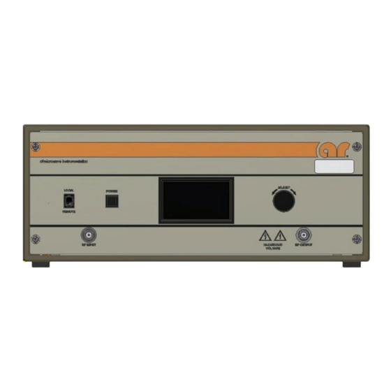
- Page 1 Operating and Service Manual 125S1G2z5 Model 10047590 Part Number Serial Number 160 School House Road, Souderton, PA 18964 • 215-723-8181 • Fax 866-859-0582 • www.arworld.us...
- Page 3 REGULATION (EC) 1907/2006 OF THE EUROPEAN PARLIAMENT AND OF THE COUNCIL of 18 December 2006 concerning the Registration, Evaluation, Authorization and Restriction of Substances of Very High Concern Chemicals (SVHC) Supporting documentation is held by AR RF/Microwave Instrumentation’s Quality department in Pennsylvania, United States. Place of issue:...
- Page 5 Instructions for European EMC Conformity WARNING It is the responsibility of the user of this equipment to provide electromagnetic shielding, filtering and isolation which is necessary for EMC compliance to Directive 2014/30/EU. The equipment must therefore be operated in a shielded area which provides a sufficient level of attenuation to meet the radiated emissions and immunity specifications.
- Page 7 The caution symbol denotes a potential hazard. Attention must be given to the statement to prevent Your AR equipment may have more than one power supply cable. Use damage, destruction, or harm. only approved power cable(s). If you have not been provided with a Dangerous voltages are present.
- Page 8 EQUIPMENT CONTAINING LASERS risk of serious injury due to unsafe AR Field Probes (FL/PL Series) and Field Analyzers (FA product handling should be a fundamental Series) are Class 1 laser products containing embedded consideration every user.
- Page 9 Zur Vermeidung von Personen- oder Sachschäden gilt BEVOR SIE DAS GERÄT ANSCHLIESSEN es, die Hinweise zu beachten. Ihre AR-Ausrüstung hat möglicherweise mehr als ein Stromversorgungskabel. Gefährliche elektrische Spannungen sind vorhanden. Verwenden Sie nur zugelassene Stromkabel. Falls Sie kein Stromkabel oder Höchste Vorsicht ist geboten.
- Page 10 Die meisten Geräte müssen während des Versands, der Montage und des Gebrauchs LASER-INFORMATION transportiert werden. Jeder Nutzer sollte sich AR - Feldsonden (FL/PL-Serie) und Feldanalysatoren (FA-Serie) über das Risiko von schweren Verletzungen sind Laserprodukte der Klasse 1 mit eingebetteten Klasse-4- durch unsachgemäße...
- Page 11 électrode de mise à la Votre équipement AR peut disposer de plus d’un câble d’alimentation terre de protection. électrique. Utilisez uniquement un ou des câbles d’alimentation approuves.
- Page 12 éliminer le risque injustifié de blessures causées par le levage est fournie par les méthodes de travail de NIOSH (publication Les sondes de champ AR (série FL/PL) et les analyseurs de n° 94-110) disponibles sur : champ (série FA) sont des produits laser de classe 1 contenant des lasers intégrés de classe 4.
- Page 13 Er zijn gevaarlijke elektrische spanningen aanwezig. Wees uiterst voorzichtig. VOOR HET OPZETTEN VAN DE STROOM Uw AR-apparatuur kan meer dan een netvoedingskabel bezitten. Gebruik alleen goedgekeurde netvoedingskabel(s). Koopt een Wijst op een terminal aan die bedoeld is voor aansluiting netvoedingskabel die is goedgekeurd voor gebruik in uw land als u...
- Page 14 APPARAAT DAT LASERS BEVAT distributie, de assemblage en het gebruik moeten worden behandeld, moet het risico AR-terreinsondes (FL/PL-serie) en terreinanalysatoren (FA- op ernstig letsel als gevolg van een serie) zijn laserproducten van klasse 1 met ingesloten onveilige behandeling van het product een klasse 4-lasers.
-
Page 15: Table Of Contents
TABLE OF CONTENTS TABLE OF CONTENTS ....................i GENERAL INFORMATION ................1 General Description ....................1 Specifications ......................1 Power Supplies ....................... 1 Installation ......................2 1.4.1 Location ........................2 1.4.2 Power ........................2 OPERATING INSTRUCTIONS ................ 9 General ........................9 Amplifier Front and Rear Panels ................ - Page 16 Model 250S1G2z5B 4.3.9 Low or No Power Output (RF Test) (Schematic 10044523) ....... 33 FIGURES Model 125S1G2z5 Front Panel ................9 Model 125S1G2z5 Rear Panel ................10 Menu Map ......................11 Typical Response at -20dBm Input and 0dBm Input ........... 33 Typical Response: Input A3-Front Panel RF Output ...........
-
Page 17: General Information
20 decibels (dB) or more. Solid state technology is used exclusively to offer significant advantages in reliability and cost. A Model 125S1G2z5, used with a frequency-swept signal source, will provide 125 watts of swept power output from 1.0–2.5 gigahertz (GHz). Typical applications include antenna and component testing, wattmeter calibration, and electromagnetic interference (EMI) susceptibility testing, as well as usage as a driver for frequency multipliers and high-power amplifiers. -
Page 18: Installation
Select an operating location that will permit air to circulate freely around the amplifier’s cabinet. The Model 125S1G2z5 utilizes air cooling and should be located where the normal flow of air into or exiting from the unit will not be restricted, diverted, or re-circulated through the unit itself; in particular, the flow of warm air exiting the rear of the amplifier should not be impeded. - Page 19 Specifications Features 125S1G2z5 The Model 125S1G2z5 is a solid-state, self- and remote control of the amplifier. The DCP contained, air-cooled, broadband amplifier uses a color LCD touch screen display to indi- 125 watts CW designed for applications where instantaneous cate the operate status and fault conditions if ...
- Page 20 DIRECTIVE 2011/65/EU SPURIOUS: Minus 73 dBc typical EXPORT CLASSIFICATION: EAR99 PRIMARY POWER: 100-240 VAC, 50/60Hz, 650 watts CONNECTORS: RF Input: N female RF Output: N female Ordering Options Contact your AR RF/Microwave Instrumentation Sales Associate for specific model configuration pricing.
- Page 21 Page 3 Graphs 125S1G2z5 125 watts CW 1.0GHz–2.5GHz...
- Page 22 Page 4 Graphs 125S1G2z5 125 watts CW 1.0GHz–2.5GHz...
- Page 23 Page 5 Envelope Drawing 125S1G2z5 125 watts CW 1.0GHz–2.5GHz To order AR Products, call 215.723.8181. For an applications engineer call:800.933.8181. Direct to Service call: 215.723.0275 or email: service@arworld.us For Faxing Orders:866.859.0582 (Orders Only Please) info@arworld.us Approved for public release by AR RF/Microwave Instrumentation...
-
Page 25: Operating Instructions
The 125S1G2z5 RF power transistors are protected from over temperature by sensing the chassis temperature near the RF output transistors. In the event of a cooling fan failure or an airflow blockage, the DC voltage will be removed from the RF stages, when the chassis temperature reaches approximately 70°C. -
Page 26: Local Control Interface
2.2.1.2 Power Button The momentary POWER button turns the main power to the 125S1G2z5 on and off. The status of the green light-emitting diode (LED) in the switch indicates whether the 125S1G2z5 power is on or off. The main power supply fans are active when power is on. The LCD touch display is active as long as the main circuit breaker for the 125S1G2z5 power entry module is on. -
Page 27: Local Operation
Model 125S1G2z5 2.2.1.5 Menu Map Figure 2-3 shows the menu map for the 125S1G2z5. The screens depicted are only example screens. The actual values and settings will be different on the actual amplifier depending on user settings and operating conditions. -
Page 28: Remote Control Interface
Model 125S1G2z5 REMOTE CONTROL INTERFACE This section describes remote operation of the 4U MPC using the provided General Purpose Interface Bus (GPIB), RS-232, Fiber-Optic Serial, Universal Serial Bus (USB), and Ethernet ports connected to a remote device such as a personal computer. All ports are active at all times, however only one port may be used at a time. -
Page 29: Fiber-Optic Serial Communication
Model 125S1G2z5 The RS-232 port is setup as a Data Circuit-terminating Equipment (DCE) port. When connecting to a Personal Computer (PC) a straight one-to-one cable should be used. A null modem is NOT needed. The settings and pinout diagram for this port can be found below. -
Page 30: Usb Communication
This port can be used in conjunction with either an AR model IF7000 RS-232 to Fiber-Optic Interface (1200 to 9600 baud only) or an AR model IF7001 USB to Fiber-Optic Interface (19200 baud only). Note that these devices use SMA connectors, so a fiber-optic cable is needed with ST connectors on one end and SMA connectors on the other. -
Page 31: Remote Commands
Lantronix Ethernet devices. This list of found devices will include any connected AR Ethernet devices. By selecting one of the connected devices from the list, its IP address and subnet mask can be changed, along with a number of other settings. -
Page 32: Relationship Between 4U Mpc Controls And Remote Communication
Model 125S1G2z5 Table 2-4. Relationship between 4U MPC Controls and Remote Communication AC Power and Power Toggle Switch Remote Circuit Breaker Communication LOCAL REMOTE Command Query √ √ √ √ √ √ √ √ √ √ √ √ √ √... - Page 33 Model 125S1G2z5 2.4.6.3 Reset Faults This will clear all faults, if possible. Syntax: RESET Parameters: None Response Format: None (No query for this command) Example: To clear any faults, send the following command: RESET<LF> 2.4.6.4 Level Adjust This command sets the RF gain of the 4U MPC.
- Page 34 Model 125S1G2z5 2.4.6.5 Identity Query to identify the 4U MPC. Syntax: *IDN? Parameters: None Query only (always requires a ? character) Response Format: f,m,n,<LF> Where: f = manufacturer m = model designation n = firmware revision Example: To get the identity of the 4U MPC, send the following command: *IDN?<LF>...
-
Page 35: States
Model 125S1G2z5 2.4.6.7 State Query to find the state of the 4U MPC. Syntax: STATE? Parameters: None Response Format: STATE=<space>xyza<LF> Where: x, y, z, and a are each an ASCII character representing a hexadecimal character. They can be 0 to 9 or A to F. - Page 36 Model 125S1G2z5 2.4.6.8 RF Gain Query to get the RF gain. Syntax: RFG? Parameters: None Response Format: RFG=<space>x<LF> Where: x = 0000 to 0100 Example: To find out the RF gain of the 4U MPC, send the following query: RFG?<LF>...
- Page 37 Model 125S1G2z5 2.4.6.10 Operating Hours (RF On) Query to get the RF On operating hours. Syntax: Parameters: None Response Format: OH=x<LF> Where: x = 0 to 100000 Units are Hours. Values can be up to six digits in length. Leading zeros are read as spaces.
- Page 38 Model 125S1G2z5 2.4.6.12 SBB (Piggyback) Firmware Revision Query to get the firmware revision of the piggyback SBB assembly. Syntax: *SBB? Parameters: None Query only (always requires a ? character) Response Format: SBB_SW_REVx<LF> Where: x = firmware revision Example: To get the firmware rev. of the piggyback SBB assembly, send the following command: *SBB?<LF>...
-
Page 39: Interlocks
Model 125S1G2z5 2.4.6.14 AC Power-On Defaults Default settings that are applied at AC mains power-on can be changed by adding the following prefix to select commands. Syntax: DEFAULT: Compatible commands: Level Adjust LEVEL:GAIN Notes: Use the command DEFAULT:FACTORY to reset all applicable settings back to their factory defaults. - Page 40 Model 125S1G2z5 Rev A...
-
Page 41: Theory Of Operation
3. THEORY OF OPERATION INTRODUCTION The Model 125S1G2z5 RF amplifier consists of a 1.0–2.5 GHz RF amplifier assembly. The RF amplifier assembly consists of a Pre-Amplifier (Pre-Amp), a Driver Quad Amplifier (Driver Amp), a two-way splitter, (2) S1G2z5 quad amplifiers, and a 2-way combiner. -
Page 42: A3 Two-Way Splitter
Model 125S1G2z5 The bias board provides the gate and drain voltages for RF FETs Q1 and Q2. The gate voltages are generated by a control loop consisting of current monitors U1, U6 and op amps U2, U7. The output voltage of U2 or U7... -
Page 43: Control System
Model 125S1G2z5 CONTROL SYSTEM 3.4.1 A12 Display Assembly, 4.3”, LCD (Schematics 10029679, 10030013) The A12 Display Assembly board consists of two 16-bit microcontrollers and about nine other ICs that monitor and indicate the status of the amplifier. Power is supplied using only a single 5-volt power supply. - Page 44 Model 125S1G2z5 Rev A...
-
Page 45: Maintenance
4. MAINTENANCE GENERAL MAINTENANCE INFORMATION The Model 125S1G2z5 requires very little maintenance since it is a relatively simple instrument. It is built with etched circuit wiring and solid-state devices that will ensure long, trouble free life. However, should trouble occur special care must be taken in servicing to avoid damage to the devices or the etched circuit board. -
Page 46: Troubleshooting
GaN HEMTs and other ESD-sensitive devices. Troubleshooting the Model 125S1G2z5 in a logical manner can speed the solution to a problem. The settings of potentiometers (pots), capacitors (caps), or other variables should not be disturbed until other problems have been eliminated. -
Page 47: General - Reading Faults
4.3.1 General - Reading Faults The Model 125S1G2z5 incorporates relatively simple fault detection circuitry, which makes use of the digital display panel to alert the user or technician which component(s) need service. Use of these indications can usually expedite troubleshooting of the amplifier. Most faults can be immediately determined down to the assembly level. -
Page 48: Interlock Fault (Schematic 10047173)
RF energy when these doors are opened. NOTE: The Model 125S1G2z5 is shipped with a mating connector, which has a jumper between Pins 1 and 8, installed in the rear panel interlock connector. The unit will not operate unless the interlock circuit is closed. -
Page 49: Low Or No Power Output (Rf Test) (Schematic 10044523)
1. The Model 125S1G2z5’s typical gain response at 0 dBm input and -20 dBm input is shown in Figures 4- 1. The actual gain may vary considerably from that shown in Figure 4-1 but should be ≥ 55.0 dBm. -
Page 50: Typical Response: Input A3-Front Panel Rf Output
Model 125S1G2z5 Phase matching must be maintained from the input of the A3 Two-Way Splitter to the inputs of the A10 Four- Way Combiner; if coaxial cables are removed, they must be reinstalled in the same locations from which they were removed. -
Page 51: Typical Four-Way Splitter Insertion Loss
Model 125S1G2z5 5. A typical Two-Way Splitter Insertion Loss is shown in Figure 4-4. The unused ports must be terminated when checking the insertion loss. Figure 4-4. Typical Four-Way Splitter Insertion Loss 6. A typical 2-Way Combiner Combined Port Return Loss is shown in Figures 4-5. The unused ports must be terminated when checking the Insertion Loss. -
Page 52: Typical A2 Driver Module Response
Model 125S1G2z5 7. The typical response for the A2 Driver Module Amplifiers shown in Figure 4-6. Figure 4-6. Typical A2 Driver Module Response NOTE: The A1 Pre-Amplifier’s response may differ considerably—particularly in flatness—from the typical responses shown in the Figure 4-7. - Page 53 These modules are not field-repairable and should never be opened outside of AR’s Microelectronics Lab. The modules in these product lines have a security label on two sides of the modules between the housing and lid/cover. If the security label is removed and or cut, the warranty of the module will be voided.
Need help?
Do you have a question about the 125S1G2z5 and is the answer not in the manual?
Questions and answers