
Related Manuals for AR 1000T2G8B


Summary of Contents for AR 1000T2G8B
- Page 1 Operating and Service Manual 1000T2G8B Model 10013175 Part Number Serial Number 160 School House Road, Souderton, PA 18964 • 215-723-8181 • Fax 215-723-5688 • www.ar-worldwide.com...
- Page 3 EC Declaration of Conformity Amplifier Research 160 School House Road Souderton, PA. 18964 declare that our product(s); the Models 1000T1G2 series, 1000T2G8 series and 1000T8G18 series RF amplifiers to which this declaration relates is in compliance with the requirements of the: EEC EMC Directive (89/336/EEC) in accordance with Article 10 (2) of the directive, with the provision that the user must install the equipment as directed by the “Instructions for European EMC Conformity”...
- Page 5 Instructions for European EMC Conformity WARNING It is the responsibility of the user of this equipment to provide electromagnetic shielding, filtering and isolation which is necessary for EMC compliance to Directive 89/336/EEC. The equipment must therefor be operated in a shielded area which provides a sufficient level of attenuation to meet the radiated emissions and immunity specifications.
- Page 7 INSTRUCTIONS FOR SAFE OPERATION BEFORE APPLYING POWER SAFETY SYMBOLS Review this manual and become familiar with all safety This symbol is marked on the equipment when it is necessary for the user to refer to markings and instructions. the manual for important safety information. Verify that the equipment line voltage selection is compatible with the main power source.
- Page 9 ADDITIONAL WARNINGS & NOTES WARNING: This equipment operates at potentially lethal voltages. Only trained, qualified personnel should operate, maintain, or service it. CAUTION: The information in this document was obtained from reliable sources and was believed to be accurate at the time of publication. Since subsequent modifications to the machine may have been made, use this information only as a guide.
-
Page 11: Table Of Contents
TABLE OF CONTENTS TABLE OF CONTENTS ....................I DESCRIPTION AND SPECIFICATIONS ............. 1 TWTA Description ....................1 Suggested Applications ..................... 1 Specifications ......................1 Accessories ........................ 1 Test Data Sheet ......................2 THEORY OF OPERATION ..................5 Design of the Amplifier ..................... 5 Control Module ...................... - Page 12 Model 1000T2G8B 5.4.7 Parts List, 1000W TWTA SC Band Continuous, 208, A28002-304 ....51 5.4.8 Parts List, RF Combiner Assy SC Band, A28005-004 ......... 52 5.4.9 Parts List, Control Unit, 1000T, 208VAC, 3-Phase, A28010-303 ....... 53 5.4.10 Parts List, 1000T S/C-Band P.S., A28012-000 ..........54 Recommended Spare Parts ..................
-
Page 13: Description And Specifications
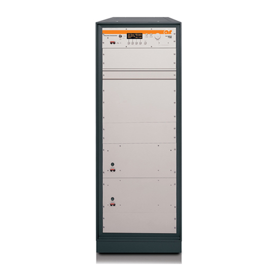
1. DESCRIPTION AND SPECIFICATIONS This manual provides operating, interfacing and selected service information pertinent to Amplifier Research Model 1000T2G8B Broadband Microwave Amplifier. The Model 1000T2G8B is a 1000 watt SC-band traveling-wave tube amplifier (TWTA). TWTA DESCRIPTION The amplifier uses two traveling wave tubes (TWTs) power combined to provide rated power output over the TWT amplifier's full bandwidth. -
Page 14: Test Data Sheet
Model 1000T2G8B TEST DATA SHEET A Test Data Sheet for a specific unit is prepared at the time of manufacture and is included with the unit's copy of this manual. Rev -... -
Page 15: Specifications
Specifications Features The Model 1000T2G8B is a self contained, a switching mode power supply results in sig- 1000T2G8B forced air cooled, broadband traveling wave nificant weight reduction. tube (TWT) microwave amplifier designed for The rated power is developed by efficiently applications where instantaneous bandwidth, ... - Page 16 Specifications Page 2 POWER (fundamental), CW, @ OUTPUT MODULATION CAPABILITY: Will faithfully reproduce 1000T2G8B CONNECTOR: AM, FM, or pulse modulation appearing on the input Nominal: 1100 watts signal. AM peak envelope power limited to specified Minimum: 900 watts minimum, 2.5–2.7GHz;...
- Page 17 46cm (18.1”), 12U x 76.5cm KVA max rear panel (30.12”), (2) 3U x 61.2cm (24.1”). To order AR Products, call 215.723.8181. For an applications engineer call:800.933.8181. Direct to Service call: 215.723.0275 or email: service@arworld.us For Faxing Orders:866.859.0582 (Orders Only Please) info@arworld.us...
-
Page 19: Theory Of Operation
2. THEORY OF OPERATION DESIGN OF THE AMPLIFIER The Model 1000T2G8B TWT amplifier consists of four principal subsystems. From top to bottom, these are the control module (A28010-303), the RF combiner assembly (A28005-004), and the two TWT power supplies (A28012-000). These will be discussed in greater detail below. The system is completed by a number of cables that interconnect the subsystems, and by the rack assembly. -
Page 20: Description Of The Twt Power Supplies
Model 1000T2G8B port. The residual harmonics are typically less than –20dBc, low enough in power that they can be further reduced, as needed, by a reflective filter without harm to the TWTs. A directional coupler is installed at the magic tee output for power metering, sample port and VSWR protection for the tubes. -
Page 21: Operation
3. OPERATION WARNINGS AND CAUTIONS Throughout this manual, the symbol: WARNING: indicates that a hazard exists that may result in personal injury or loss of life. CAUTION: indicates that failure to follow procedures may result in damage to the equipment. WARNING: DANGER - High Voltage Present: Electrical equipment in this TWTA generates and stores high-voltage energy that can result in fatal electrocution. -
Page 22: Installation
Model 1000T2G8B INSTALLATION 3.2.1 Unpacking Upon receiving the TWTA, inspect the shipping container for obvious signs of external damage. If damage is observed, notify the carrier and contact an authorized service representative. One panel of the shipping container can be removed to gain access to the TWTA. This panel may be positioned to use as a ramp when removing the TWTA from the shipping container. -
Page 23: Ac Line Power Connections
Model 1000T2G8B 3.2.4 AC Line Power Connections AC line power connection to the TWTA is a 5-conductor cable attached the junction box. The cable is provided unterminated, and appropriate wiring to the cable must be provided by the user. The cable conductor... -
Page 24: Front Panel Features
Model 1000T2G8B CAUTION: Do not rely on the external interlock for personnel protection. The intent of the external interlock feature is to disable the RF output for equipment protection. Use proper operating and safety procedures to ensure that power is removed for personnel safety. -
Page 25: Front Panel Features
Model 1000T2G8B Table 3-1. Front Panel Features Label Title Function MAIN POWER Switchable 7.5 A. circuit breaker; turns on control module, closes contactor providing AC to the power supply assemblies. OPERATE Push-button; turns on high voltage when all faults and heater delay are cleared. -
Page 26: Front Panel Display And Soft Keys
Model 1000T2G8B FRONT PANEL DISPLAY AND SOFT KEYS The purpose of the front panel display is to permit the operator to access extensive information about the condition and operation of the TWTA. To accomplish this, a number of informational screens are programmed. - Page 27 Model 1000T2G8B Menu screens - The screens at the highest level are called menu screens. There are five menu screens. At power on, the MENU 1 screen is displayed. Each of the menu screens has the soft key S4 labeled MORE. The MORE key (S4) causes the next menu screen to appear.
- Page 28 Model 1000T2G8B (Sleep Mode activated). This eliminates excessive STANDBY hours on the TWTs while still permitting remote capability to turn on the amplifier. After activating the Sleep Mode: Screen will display Cooling On while heaters cool down. System Off notifies user that the amplifier is in...
- Page 29 Model 1000T2G8B System Shutdown Screen - In the event of a system shutdown due to a fault, refer to Table 3-5. The MENU screen is replaced by a screen indicating the nature of the fault. Softkey S4 (labeled OK) is implemented as a reset key;...
-
Page 30: Rear Panel Features
Model 1000T2G8B REAR PANEL FEATURES Rear Panel Features Figure 3-3. Rev -... -
Page 31: Initial Turn On And Warm-Up Procedure
Model 1000T2G8B Table 3-2. TWTA Rear Panel Features Label Title Function 208 VAC IN AC power input cable REMOTE INTERFACE Remote control connector. 24 pin hermaphrodite AIR FILTER Cooling air intake. EXHAUST FAN Cooling air outlet. RF OUT Type WRD-250D30 flange... -
Page 32: Remote Ieee-488 Operation
Model 1000T2G8B output. Do not set input drive above 0dBm (Input drive above +13dBm may damage the unit). The reverse power level should remain below 10% of the forward power, assuming that the load is properly matched. An alternate procedure is to pre-set the TWTA gain to minimum, set the RF generator to 0dBm and then slowly increase the TWTA gain to set the desired RF output level. - Page 33 Model 1000T2G8B Command Function Units Response format RDTMPTWTHPA1C Returns TWT temp (°C), HPA1 °C TWTHPA1C=[ ]C RDTMPTWTHPA2C Returns TWT temp (°C), HPA2 °C TWTHPA2C=[ ]C RDTMPPSHPA1F Returns power supply temp (°F), HPA1 °F PSHPA1F=[ ]F RDTMPPSHPA2F Returns power supply temp (°F), HPA2 °F...
-
Page 34: Catalog Of Status Codes
Model 1000T2G8B Table 3-4. Catalog of Status Codes (The RDSTAT command causes the TWTA to return a string in the form STATUS=[code], where [code] is an ASCII number whose meaning is given below) Status Code Meaning No command was given or last command was successful. -
Page 35: Catalog Of System State Codes
Model 1000T2G8B Table 3-6. Catalog of System State Codes (The RDLOGIC command causes the TWTA to send a string containing an operational state code consisting of 4 ASCII characters representing hex digits. The response is in the form Sys:[w][x][y][z][eol] where the hex... -
Page 36: Catalog Of *Stb?; Response Codes
Model 1000T2G8B Table 3-8. *STB?; Response Codes (The command *STB?; causes the TWTA to send a string containing an operational state code consisting of 2 ASCII characters representing hex digits. The response is in the form STATUS:[x][y][eol] where the hex... -
Page 37: Twta General Considerations
Cooling during Operate Mode: AR TWTAs have their air outlets and inlets on the rear panels. It is important to prevent the heated air, which is expelled from the TWTA’s air outlets, from being recycled into the air inlets. - Page 38 Model 1000T2G8B Noise Power Density (NPD): TWTAs produce RF noise over their operating frequency range, as specified by the Noise Power Density (NPD). This noise is significantly higher than the noise produced by typical solid state amplifiers, and is inherent in present TWTAs. The noise may surprise users new to TWTAs when it accumulates and results in a significant indication in a broadband measurement device –...
- Page 39 Model 1000T2G8B The service measures involve pulsing of the tube beam current and gradually increasing the duty of the pulsing until the unit will operate continuously. Note that a similar condition can exist for tubes with grids when the TWTA is in the Operate mode (high voltage is on) but gating (control) input is set so that the grid turns off the TWT beam current.
- Page 40 Model 1000T2G8B Rev -...
-
Page 41: Maintenance
5. MAINTENANCE The TWTA requires a minimum of routine maintenance. The only moving parts are the elements of switches, relays and blowers. Preventive maintenance is recommended in Paragraph 4.3. In the event that the TWTA needs repairs, it is recommended that the unit be returned to the factory. However, some user service organizations may choose to perform their own corrective maintenance, and under some circumstances returning the unit to the factory may be impractical. - Page 42 Model 1000T2G8B If there is accumulated dust on any of the air intake filters, remove them and clean them with dry compressed air. If the filters show signs of deterioration, purchase replacement units. If significant dust has been noted on the air intake filters, it may be desirable to vacuum the dust and debris from inside the enclosure.
-
Page 43: Troubleshooting
Model 1000T2G8B TROUBLESHOOTING Symptom Possible cause TWT or power supply overtemperature Air inlet filter(s) dirty Collector heat sink dirty Inadequate clearance behind TWTA High air inlet temperature Defective fan or fan driver No response when main power turned on Disconnected power cable Defective circuit breaker Control module display does not come up;... - Page 44 Model 1000T2G8B Rev -...
-
Page 45: Technical Documentation
5. TECHNICAL DOCUMENTATION NOTE: The purpose of this technical documentation section is to provide a guide to the TWTA for technician- level servicing. It is intended for use by qualified technical personnel who must troubleshoot and repair the TWTA in the field. Such repairs are typically limited to replacement of modules or major components. - Page 46 Model 1000T2G8B Rev -...
-
Page 47: Top Level Build Tree
Model 1000T2G8B TOP LEVEL BUILD TREE A28002-304 1000W TWTA SC BAND CONTINUOUS, 380 VAC 3-PHASE, A28005-004 RF COMBINER ASSY SC BAND CONTINUOUS, FRONT 1A1A1 A27995-003 COMBINER RF COMPONENTS, 1000T SC BAND, WG A31673-000 COMBINER ASSEMBLY, WRD-250, S/C BAND [MDC 1A1A2... - Page 48 DATA STEERING BOARD (7 PORT) 1A4A5-A7 A28008-000 F/O TO RS-485 ADAPTER 1A4A9 A28046-000 CONTROL MODULE WIRING KIT 1A4A10 A28045-000 CONTROL MODULE CABINET ASSY AR 1000T, 380VAC 1A7-A8 A28014-000 TWT CONTROL CABLE A28015-000 COMBINER CONTROL CABLE 1A11 A30921-000 CABINET KIT 1000T...
-
Page 49: Schematics
Model 1000T2G8B SCHEMATICS 10-16485-000 HPA Logic and Control (A16485-000) 10-24830-002 Remote Control Board, Foldback only (A24830-002) 10-25444-000 HPA Interface (A25444-000) 10-27444-000 Switcher/Combiner Interface Board (A27444-001) 10-28005-001 RF Combiner, SC-band (A28005-004) 10-28010-300 Control Module, 1000T (A28010-303) 10-28012-000 1000T SC-Band Power Supply (A28012-000) - Page 50 Model 1000T2G8B Rev -...
-
Page 51: Block Diagram
Model 1000T2G8B BLOCK DIAGRAM 25-28005-000 RF Combiner for L-Band (A28005-004) Rev -... - Page 52 Model 1000T2G8B Rev -...
-
Page 53: Parts Lists
Model 1000T2G8B PARTS LISTS A16485-000 HPA Logic and Control Module A24801-501 1000T 3U Power Supply for TWT 5196 A24830-002 Emergency Bypass Board A25444-000 HPA interface A27444-001 Switcher/Combiner Interface Board A27995-003 Combiner RF Components 1000T-SC A28002-304 1000 W TWTA S/C-Band, 208VAC... -
Page 54: Parts List, Hpa Logic And Control Module, A16485-000
Model 1000T2G8B 5.4.1 Parts List, HPA Logic and Control Module, A16485-000 REF. DESIG. ETM P/N DESCRIPTION QUANTITY B16485-000 HPA LOGIC AND CONTROL BOARD C16333-000 CAP,33MF,25V,AERL,(NICHICON UVX1E330M) C2, C5, C15, C58 C31028-000 CAP,1000PF,200VDC,10%,CER,1% FAILURE,(KEMET CKR05 SERIES W/"V" OPTION) C3, C9, C10, C13, C14, C17, C31032-000 CAP,0.01MF,200VDC,10%,CER,1% FAILURE,(KEMET... - Page 55 Model 1000T2G8B REF. DESIG. ETM P/N DESCRIPTION QUANTITY R21953-000 RES,9.53K,1/2W,1%,MF,100PPM,(DALE RN55D) R47, R48 R22200-000 RES,20K,1/2W,1%,MF,100PPM,(DALE RN55D) R79, R80 R22470-000 RES,47K,1/2W,1%,MF,100PPM,(DALE RN55D) R42, R60, R61, R89 R23100-000 RES,100K,1/2W,1%,MF,100PPM,(DALE RN55D) R33, R55 R23698-000 RES,698K,1/2W,1%,MF,100PPM,(DALE RN55D) R23750-000 RES,750K,1/2W,1%,MF,100PPM,(DALE RN55D) R23845-000 RES,845K,1/2W,1%,MF,100PPM,(DALE RN55D) R23953-000...
-
Page 56: Parts List, 3U Power Supply For Twt 5196, 1 Phase, A24801-501
Model 1000T2G8B 5.4.2 Parts List, 3U Power Supply for TWT 5196, 1 Phase, A24801-501 REF. DESIG. ETM P/N DESCRIPTION QUANTITY A10010-000 HEATER POWER SUPPLY MODULE A10017-511 PWM BD FOR 500T2G8 A16485-000 HPA LOGIC AND CONTROL MODULE A21422-000 GRID MODULATOR MODULE... -
Page 57: Parts List, Emergency Bypass Board, A24830-002
Model 1000T2G8B 5.4.3 Parts List, Emergency Bypass Board, A24830-002 REF. DESIG. ETM P/N DESCRIPTION QUANTITY B24830-000 EMERGENCY BYPASS BOARD C3-C5 C04105-000 CAP,0.1MF,100V,20%,MON,(KEMET C331C104M1R5CA) C06103-000 CAP,10MF,25V,20%,SOLID TANT,RADIAL,(AVX TAP106M025HSB) C1, C2 C31032-000 CAP,0.01MF,200VDC,10%,CER,1% FAILURE,(KEMET CKR06 SERIES W/"V" OPTION) C31040-000 CAP,1MF,50VDC,10%,CER,1% FAILURE,(KEMET CKR06 SERIES W/"V" OPTION) -
Page 58: Parts List, Hpa Interface Board (Plastic Fibers), A25444-000
Model 1000T2G8B 5.4.4 Parts List, HPA Interface Board (Plastic Fibers), A25444-000 REF. DESIG. ETM P/N DESCRIPTION QUANTITY B25444-000 HPA INTERFACE BOARD C161 C03105-000 CAP,0.01MF,100V,CER,10%,RADIAL,(AVX SR201C103KAA) C171 C04223-000 CAP,0.22MF,35V,TANT,RADIAL, [JAMCO 33507] C20, C32, C100 C05153-000 CAP,1.5MF,35V,TANT,RADIAL,(JAMECO TM1.5/35) C129, C163 C05223-000 CAP,2.2MF,35V,10%,SOLID SEALED... - Page 59 Model 1000T2G8B REF. DESIG. ETM P/N DESCRIPTION QUANTITY J16214-000 TEST JACK,YELLOW,VERTICAL,(EF JOHNSON 105- 0857-001) J16215-000 TEST JACK,GREEN,VERTICAL,(EF JOHNSON 105- 0854-001) J16216-000 TEST JACK,BLUE,VERTICAL,(EF JOHNSON 105- 0860-001) J18167-000 D-SUB,37 PIN,FEMALE,PCB MOUNT,RIGHT ANGLE (AMP 745784-4) J18180-000 CONN,D-SUB,15 PIN,MALE,STRAIGHT,PCB MOUNT (POSITRONIC MD15M3000) J31013-000...
- Page 60 Model 1000T2G8B REF. DESIG. ETM P/N DESCRIPTION QUANTITY U6, U19, U34, U39, U60 U20148-000 IC,HEX INVERTER,SCHMIDTT TRIGGER,(74HC14) (SSD) U20730-000 IC,DUAL J-K FLIP FLOP W/RESET,(7473) (SSD) U21328-000 IC,QUAD 2 INPUT NAND,SCHMIDTT TRIGGER,(74HC132) (SSD) U21388-000 IC,3 TO 8 DECODER/DEMULTIPLEXER, INVERTING, (74HC138) (SSD)
-
Page 61: Parts List, 1000T Combiner Vpc Interface A27444-001
Model 1000T2G8B 5.4.5 Parts List, 1000T Combiner VPC Interface A27444-001 REF. DESIG. ETM P/N DESCRIPTION QUANTITY REV D B27444-000 COMBINER INTERFACE C13, C49 C04105-000 CAP,0.1MF,100V,20%,MON,(KEMET C331C104M1R5CA) C144, C148 C04223-000 CAP,0.22MF,35V,TANT,RADIAL, [JAMCO 33507] C1, C19, C24 C05153-000 CAP,1.5MF,35V,TANT,RADIAL,(JAMECO TM1.5/35) C142, C143 C05223-000 CAP,2.2MF,35V,10%,SOLID SEALED... - Page 62 Model 1000T2G8B REF. DESIG. ETM P/N DESCRIPTION QUANTITY J31010-000 CONN,D-SUB,15 PIN,MALE,RIGHT ANGLE,PCB MOUNT,[AMPHENOL 617-A015P-AJ121] J31013-000 CONN,D-SUB,25 PIN,MALE,RIGHT ANGLE,PCB MOUNT,[AMP 747238-4] J31014-000 SPRING LATCH KIT,D-SUB,(AMPHENOL 17-529) K1-K16 K02009-000 RELAY,DPDT,5VDC,125V @ 0.5A / 30VDC @ 1A CONTACTS,PCB TERMINALS,SEALED (OMRON G6H-2-DC5) L1-L4 L00200-000...
- Page 63 Model 1000T2G8B REF. DESIG. ETM P/N DESCRIPTION QUANTITY U23909-000 IC,DUAL 4 BIT BINARY/BIQUINARY COUNTER (74HCT390) (SSD) U28, U52 U24018-000 IC,JOHNSON DECADE COUNTER W/10 DECODED OUTPUTS,(74HC4017) (SSD) U24138-000 IC,8 BIT BINARY DOWN COUNTER,(74HC40103) (SSD) U26889-000 IC,8 BIT MAGNITUDE COMPARATOR,(74HCT688) (SSD) U16, U48, U68...
-
Page 64: Parts List, Combiner Rf Components, 1000T Sc, A27995-003
Model 1000T2G8B 5.4.6 Parts List, Combiner RF Components, 1000T SC, A27995-003 REF. DESIG. ETM P/N DESCRIPTION QUANTITY A31673-000 COMBINER ASSEMBLY, WRD-250, S/C BAND [MDC TBD] A5, A6 E01608-000 TWT, 2.5-7.5 GHZ, 535 W, GRID, WRD-250,+/-2 DB EQ, PHASE COMB, ISO THERMO (MEC-5498,... -
Page 65: Parts List, 1000W Twta Sc Band Continuous, 208, A28002-304
A28002-304 REF. DESIG. ETM P/N DESCRIPTION QUANTITY A28005-004 RF COMBINER ASSY SC BAND CONTINUOUS, FRONT PORTS A28010-300 CONTROL UNIT, 1000T, 380VAC, 3-PHASE (AR) A2, A3 A28012-000 1000T S/C-BAND P.S. A8, A7 A28014-000 TWT CONTROL CABLE A28015-000 COMBINER CONTROL CABLE A30921-000... -
Page 66: Parts List, Rf Combiner Assy Sc Band, A28005-004
Model 1000T2G8B 5.4.8 Parts List, RF Combiner Assy SC Band, A28005-004 REF. DESIG. ETM P/N DESCRIPTION QUANTITY A3, A4 A26941-000 TWTA LOP BOARD A27444-001 1000T COMBINER VPC INTERFACE BOARD, COMPONENT SIDE CONNECTORS A27995-003 COMBINER RF COMPONENTS, 1000T SC BAND, WG OUTPUT TWT,NO SUBBAND SWITCHING, WITH INT. -
Page 67: Parts List, Control Unit, 1000T, 208Vac, 3-Phase, A28010-303
DATA STEERING BOARD (7 PORT) A25403-300 TWTA CONTROL ASSY 20 CIJ/50X A5-A7 A28008-000 F/O TO RS-485 ADAPTER A28045-000 CONTROL MODULE CABINET ASSY AR 1000T, 380VAC A28046-000 CONTROL MODULE WIRING KIT E00765-000 P.S.,85-264VAC,47-440HZ TO 5VDC & 3.0A,(KEPCO FAW 5-3K/CA 24) E00810-000... -
Page 68: Parts List, 1000T S/C-Band P.s., A28012-000
Model 1000T2G8B 5.4.10 Parts List, 1000T S/C-Band P.S., A28012-000 REF. DESIG. ETM P/N DESCRIPTION QUANTITY A23692-000 INSULATED FAN DRIVER A24801-501 3U POWER SUPPLY FOR TWT 5196, 1 PHASE A25444-000 HPA INTERFACE BOARD (PLASTIC FIBERS) A27772-000 1000T S/C-BAND CABINET ASSY A28008-000... -
Page 69: Recommended Spare Parts
Model 1000T2G8B RECOMMENDED SPARE PARTS A10010-000 Heater Supply Module A21422-000 Grid Modulator Assembly A21461-500 HV Filter A21425-500 Diode/Cap Assembly A16487-000 Power Board Assembly A23687-001 Low Voltage Power Supply Module A23683-000 Average Current Power Factor 100V-250V A23692-000 Insulated Fan Driver N26677-000... -
Page 70: Sample Program For Ieee-488 Communication
Model 1000T2G8B SAMPLE PROGRAM FOR IEEE-488 COMMUNICATION 1000 ! *********************************************** 1010 IEEE-488 COMMUNICATIONS SOFTWARE 1030 7/24/92 AARON D. McCLURE 1040 ! *********************************************** 1041 DIM F$[80] 1042 DIM A$[80] 1050 CLEAR SCREEN 1060 INPUT "INPUT COMMAND TO SEND TO POWER SUPPLY. - Page 71 Meters, Directional Couplers, Field Monitoring Equipment, Conducted Immunity Generators, Signal Generators and Tripods will be free from defects in material and workmanship for a period of three (3) years from date of shipment shown on AR RF/Microwave Instrumentation invoice. Traveling Wave Tubes in the 200T2G8A, 250T1G3 and 250T8G18 will be free from defects in material and workmanship for a period of two (2) years from date of shipment.
Need help?
Do you have a question about the 1000T2G8B and is the answer not in the manual?
Questions and answers