
Related Manuals for AR 200T26z5G40A Series


Summary of Contents for AR 200T26z5G40A Series
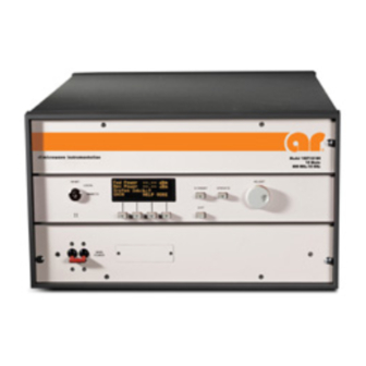
- Page 1 Operating and Service Manual 200T26z5G40A Model 10027190 Part Number Serial Number 160 School House Road, Souderton, PA 18964 • 215-723-8181 • Fax 215-723-5688 • www.arworld.us...
- Page 3 Amplifier Research 160 School House Road Souderton, PA. 18964 declare that our product(s); the Model 200T26z5G40A series RF amplifiers to which this declaration relates is in compliance with the following European directives: Low Voltage Directive: 2014/35/EU EMC Directive: 2014/30/EU Supplementary Information:...
- Page 5 Avoid sudden care. stops and uneven surfaces. BEFORE APPLYING POWER Indicates a terminal intended for connection to an Your AR equipment may have more than one power supply external conductor protection against cable. Use only approved power cable(s). If you have not been...
- Page 6 EQUIPMENT CONTAINING LASERS to unsafe product handling should be AR Field Probes (FL/PL Series) and Field Analyzers a fundamental consideration of every (FA Series) are Class 1 laser products containing user. An authoritative guideline for embedded Class 4 lasers.
- Page 7 ADDITIONAL WARNINGS & NOTES WARNING: This equipment operates at potentially lethal voltages. Only trained, qualified personnel should operate, maintain, or service it. Hazardous energy may be present while protective covers are removed from the equipment even if disconnected from the power source. Contact may result in personal injury.
-
Page 9: Table Of Contents
TABLE OF CONTENTS TABLE OF CONTENTS ....................i DESCRIPTION AND SPECIFICATIONS ............1 TWTA Description ....................1 Suggested Applications ..................1 Specifications ......................1 Accessories ......................1 Test Data Sheet ...................... 2 THEORY OF OPERATION ................5 Design of the amplifier ................... 5 Description of the RF aSSEMBLY ................ - Page 10 Parts List, VSWR/Foldback Board Assembly, A32363-000 ....... 47 5.3.9 Parts List, HPA 200 Watt K-Band W/ 2 L3 Tubes (AR), A33961-000 ....49 5.3.10 Parts List, HPA 200 Watt KA-Band W/ 2 L3 Tubes (AR), A33962-000 .... 49 Sample Program ....................50 Figures Rack Mounting Configuration ................
-
Page 11: Description And Specifications
• Equipment calibration • General laboratory instrumentation SPECIFICATIONS Refer to the AR Data Sheet at the end of this section for detailed specifications. ACCESSORIES AR offers a number of accessories for use with this amplifier including: • Directional coupler •... -
Page 12: Test Data Sheet
Models 200T18G26z5A/200T26z5G40A TEST DATA SHEET A Test Data Sheet for a specific unit is prepared at the time of manufacture and is included with the unit's copy of this manual. Rev –... - Page 13 RF components allow for easy access and repair. Use of a switching mode power supply results in significant weight reduction. Model 200T26z5G40 Typical Power Output AR RF/Microwave Instrumentation 160 School House Rd Souderton, PA 18964 215-723-8181 For an applications engi- neer call:800.933.8181...
- Page 14 Handles: Front handles installed. Model number example: Model 200T26z5G40AM2 would have option E3H front handles installed. To order AR Products, call 215.723.8181. For an applications engineer call:800.933.8181. Direct to Service call: 215.723.0275 or email: service@arworld.us For Faxing Orders:866.859.0582 (Orders Only Please) info@arworld.us...
-
Page 15: Theory Of Operation
2. THEORY OF OPERATION DESIGN OF THE AMPLIFIER The TWT amplifier consists of four principal subsystems. Two of these subsystems, the microwave power assembly and the TWT power supplies are discussed in sections 2.2 and 2.3, respectively. The other two subsystems are the microprocessor control system and the TWTA packaging. These both consist of a number of subassemblies. -
Page 16: Description Of The Power Supply
Models 200T18G26z5A/200T26z5G40A Amplifier gain is determined by a single solid-state preamp (SSPA), which has a voltage-controlled attenuator. The control head determines the output of a digital-to-analog converter (DAC) on the HPA interface board. The output of the DAC controls the SSPA attenuator. DESCRIPTION OF THE POWER SUPPLY The two TWT power supplies are of modular construction. -
Page 17: Operation
3. OPERATION WARNINGS AND CAUTIONS Throughout this manual, the symbol: WARNING: Indicates that a hazard exists that may result in personal injury or loss of life. CAUTION: Indicates that failure to follow procedures may result in damage to the equipment. WARNING: DANGER - High Voltage Present: Electrical equipment in this TWTA generates and stores high-voltage energy that can result in fatal electrocution. -
Page 18: Mounting
Models 200T18G26z5A/200T26z5G40A 3.2.2 Mounting The TWTA may be operated as a standalone bench top unit or it may be installed in a 19" rack. If rack mounting is desired, first remove the amplifier from the cabinet, then install the amplifier in the rack. CAUTION: Due to the weight of the unit, the removal of the amplifier from the cabinet or rack is a two-person operation. -
Page 19: Cooling Requirements
Models 200T18G26z5A/200T26z5G40A 3.2.3 Cooling Requirements The TWTA is provided with two cooling fans. It is important that air movement around the rear of the unit be unobstructed. CAUTION: For either bench or rack mounting, do not position the TWTA in such a way that the air intakes or outlets are blocked, or that the exhaust flows are directed into the intakes. -
Page 20: External Interlock Connector
Models 200T18G26z5A/200T26z5G40A CAUTION: Never operate the TWTA without a matched output load rated for at least 300 watts, continuous. Full reflected power may irreparably damage the TWT. Even with no drive, “looping” oscillation can result in RF output high enough to damage the tube if it is operated without a load. -
Page 21: Front Panel Features
Models 200T18G26z5A/200T26z5G40A FRONT PANEL FEATURES Refer to Figure 3-2 below. Figure 3-2. Front Panel Features Table 3-1. Front Panel Features Item Title Function MAIN POWER Switchable 16 A. circuit breaker; Turns ON/OFF system power. OPERATE Push-button; turns on high voltage and SSA when all faults and heater delay are cleared. STANDBY Push-button;... -
Page 22: Front Panel Display And Soft Keys
Models 200T18G26z5A/200T26z5G40A FRONT PANEL DISPLAY AND SOFT KEYS The purpose of the front panel display is to permit the operator to access extensive information about the condition and operation of the TWTA. To accomplish this, a number of informational screens are programmed. - Page 23 Models 200T18G26z5A/200T26z5G40A Menu screens - The screens at the highest level are called menu screens. There are seven menu screens. At power on, the MENU 1 screen is displayed. Each of the menu screens has the soft key S4 labeled MORE. The MORE key (S4) causes the next menu screen to appear.
- Page 24 Models 200T18G26z5A/200T26z5G40A To activate Sleep Mode locally: Press the MORE soft key to get to MENU 2. At MENU 2 press the SETUP soft key to get to SETUP 1. At SETUP 1 press SET to activate Sleep Mode (turn heater and fan off). The system will ask are you sure? Press SET again.
- Page 25 Models 200T18G26z5A/200T26z5G40A System Shutdown Screen - In the event of a system shutdown due to a latched fault (i.e., a fault such as body overcurrent or power low line that requires a reset), the MENU screen is replaced by a screen indicating the nature of the fault.
-
Page 26: Rear Panel Features
Models 200T18G26z5A/200T26z5G40A REAR PANEL FEATURES See Figure 3-4 below. Figure 3-4. Rear Panel Features Table 3-2. TWTA Rear Panel Features Item Title Function AC POWER IN AC power input connector: MS 3102R-18-10P connector IEEE-488 Remote control connector: 24 pin hermaphrodite EXTERNAL INTERLOCK Connector to remote temperature switch protecting the isolator load: D-sub 15-pin female —... -
Page 27: Initial Turn On And Warm-Up Procedure
Models 200T18G26z5A/200T26z5G40A INITIAL TURN ON AND WARM-UP PROCEDURE Install the TWTA as discussed in section 3.2. Connect a suitable RF generator to the RF input Type K connector. Set RF generator level below -50 dBm and set desired frequency in specified range. Connect a load suitable for 300 watts continuous operation to the output waveguide flange. -
Page 28: Foldback Operation
Models 200T18G26z5A/200T26z5G40A FOLDBACK OPERATION Forward FOLDBACK and reverse FOLDBACK circuits are used on both the 18G26z5 and 26z5G40. In the event the output power exceeds or the reflected power exceed factory limits a fold back circuit will active, and control the solid-state amplifier attenuation to ensure the output power is kept to fixed limit. Forward Fold back The forward FOLDBACK protection circuit will activate if RF output power exceed 250W. - Page 29 Models 200T18G26z5A/200T26z5G40A Command Function Units Response format RDEF1 Returns heater voltage, HPA1 Ef=[ ] RDEF2 Returns heater voltage, HPA2 Ef=[ ] RDIF1 Returns heater current, HPA1 If=[ ] RDIF2 Returns heater current, HPA2 If=[ ] RDIW1 Returns helix current, HPA1 Iw=[ ] RDIW2 Returns helix current, HPA2...
-
Page 30: Catalog Of Status Codes
Models 200T18G26z5A/200T26z5G40A Table 3-4. Catalog of Status Codes (The RDSTAT command causes the TWTA to return a string in the form STATUS=[code], where [code] is an ASCII number whose meaning is given below) Status Code Meaning No command was given. Last command successful. -
Page 31: Catalog Of System State Codes
Models 200T18G26z5A/200T26z5G40A Table 3-6. Catalog of System State Codes (The RDLOGIC command causes the TWTA to send a string containing an operational state code consisting of 4 ASCII characters representing hex digits. The response is in the form Sys:[w][x][y][z][eol] where the hex values of [w],[x],[y] and [z] are formed as shown below) z bit Meaning... -
Page 32: Catalog Of *Stb?; Response Codes
Models 200T18G26z5A/200T26z5G40A Table 3-8. *STB?; Response Codes (The command *STB?; causes the TWTA to send a string containing an operational state code consisting of 2 ASCII characters representing hex digits. The response is in the form STATUS:[x][y][eol] where the hex values of [x] and [y] are formed as shown below) y bit Meaning... -
Page 33: Twta General Considerations
Cooling during Operate Mode: AR TWTAs have their air outlets and inlets on the rear panels. It is important to prevent the heated air, which is expelled from the TWTA’s air outlets, from being recycled into the air inlets. - Page 34 Models 200T18G26z5A/200T26z5G40A if needed up to 25 times, until the Operate mode is actually set. If this condition persists, contact AR Service for additional assistance. (See Explanation of…, below) Noise Power Density (NPD): TWTAs produce RF noise over their operating frequency range, as specified by the Noise Power Density (NPD).
- Page 35 Models 200T18G26z5A/200T26z5G40A unit. Thus, users should reduce the likelihood of occurrence of this problem by limiting the amount of time in the Standby mode. The service measures involve pulsing of the tube beam current and gradually increasing the duty of the pulsing until the unit will operate continuously.
- Page 36 Models 200T18G26z5A/200T26z5G40A Rev –...
-
Page 37: Maintenance
4. MAINTENANCE The TWTA does not require routine scheduled maintenance. The only moving parts are the elements of switches, relays and blowers. Preventive maintenance is recommended in Paragraph 4.3. The TWTA is basically a factory repairable unit. However, since limited logic schematics and partial parts information is supplied in this manual (Section 5) some user service organizations may choose to perform their own corrective maintenance. -
Page 38: Troubleshooting
Models 200T18G26z5A/200T26z5G40A To open the enclosure: 1. Remove the amplifier from the cabinet or rack as follows: NOTE: Due to the weight of the unit, the removal of the amplifier from the cabinet or rack is a two person operation. Disconnect power, RF, and any other interface connectors. -
Page 39: Non-Repairable Modules
Models 200T18G26z5A/200T26z5G40A NON-REPAIRABLE MODULES The High Voltage Diode/Cap Assembly, the High Voltage Filter Assemblies, and the Heater Supply are encapsulated modules and are not repairable. Contact an authorized service representative if replacement modules are needed. Rev –... - Page 40 Models 200T18G26z5A/200T26z5G40A Rev –...
-
Page 41: Technical Documentation
5. TECHNICAL DOCUMENTATION NOTE: The purpose of this technical documentation section is to provide a guide to the TWTA for technician-level servicing. It is intended for use by qualified technical personnel who must troubleshoot and repair the TWTA in the field. Such repairs are typically limited to replacement of modules or major components. -
Page 42: Top Level Build Tree
TOP LEVEL BUILD TREE 5.1.1 A33961-000, 200 Watt K Band HPA REF. DESIG. ETM P/N DESCRIPTION A33961-000 HPA 200 WATT K-BAND W/ 2 L3 TUBES (AR) A34032-000 RF DRAWER 200 WATT K-BAND A34208-000 CABINET KIT, 200K RF DRAWER 1A1A1 A28051-341... -
Page 43: A33962-000, 200 Watt Ka Band Hpa
5.1.2 A33962-000, 200 Watt KA Band HPA REF. DESIG. ETM P/N DESCRIPTION A33962-000 200 WATT KA-BAND HPA W/ 2 L3 TUBES (AR) A34033-000 RF DRAWER 200 WATT KA-BAND A34210-000 CABINET KIT, 200KA RF DRAWER A34210-001 CABINET KIT, 200KA RF DRAWER... -
Page 44: Schematics
Models 200T18G26z5A/200T26z5G40A SCHEMATICS 10-16485-893 HPA Logic and Control (A16485-893 for 18G26 & 26G40) 10-25444-001 HPA Interface (A25444-001) 10-32363-000 VSWR & FOLDBACK board assembly (A32363-000) 10-24830-011 Emergency bypass board, low level fold back (A24830-011) 10-33961-000 HPA 200T K & Ka Band (18G26 & 26G40) Rev –... -
Page 45: Parts Lists
Emergency Bypass Foldback board A25444-001 HPA Interface Board (200UM Glass) A28051-341 18G26 Microwave Assembly A28051-351 26G40 Microwave Assembly A28052-002 Wring Kit 200 K & Ka A32363-000 VSWR & fold back board assembly A33961-000 200T18G26z5A TWTA (AR) A33962-000 200T26z5G40A TWTA (AR) Rev –... -
Page 46: Parts List, 200T 18G26Z5A & 26Z5G40A, Hpa Logic And Control Module For 130K, 130Ka, A16485-893
Models 200T18G26z5A/200T26z5G40A 5.3.1 Parts List, 200T 18G26z5A & 26z5G40A, HPA Logic and Control Module for 130K, 130KA, A16485-893 REF. DESIG. ETM P/N DESCRIPTION QUANTITY HPA LOGIC AND CONTROL MODULE FOR 130K, A16485-893 130KA (10US VSWR), FIXED VSWR REF. B16485-000 HPA LOGIC AND CONTROL BOARD CAP,33UF,25V,AERL,5MM DIAM (NICHICON, C16333-000 UVR1E330MDD) - Page 47 Models 200T18G26z5A/200T26z5G40A REF. DESIG. ETM P/N DESCRIPTION QUANTITY TRIMPOT,5K,1/2W,10%,CERMET,20T,SIDE R13, R14 R10002-000 ADJ,(BOURNS 3296X-1-502) R21499-000 RES,4.99K, 1%,MF,100PPM,(DALE RN55D4991F) R21523-000 RES,5.23K, 1%,MF,100PPM,(DALE RN55D) R21866-000 RES,8.66K, 1%,MF,100PPM,(DALE RN55D) R52, R73 R21887-000 RES,8.87K, 1%,MF,100PPM,(DALE RN55D) R21953-000 RES,9.53K, 1%,MF,100PPM,(DALE RN55D9531F) R21, R47, R48 R22200-000 RES,20K, 1%,MF,100PPM,(DALE RN55D2002F) R79, R80 R22470-000...
-
Page 48: Parts List, 200T18G26Z5A, Hv Power Supply For L-3 Twt 8928H (Pulsed 2-Tube Unit), A22826-930
Models 200T18G26z5A/200T26z5G40A 5.3.2 Parts List, 200T18G26z5A, HV Power Supply For L-3 TWT 8928H (Pulsed 2-Tube Unit), A22826-930 REF. DESIG. ETM P/N DESCRIPTION QUANTITY A10007-000 ANODE MODULE ASSY PWM BD FOR 130K & 130KA, -14KV REG, PULSE + A10017-892 HPA LOGIC AND CONTROL MODULE FOR 130K, A16485-893 130KA (10US VSWR), FIXED VSWR REF. -
Page 49: Emergency Bypass Board, Low Level Foldback Trip (<1V); A24830-011
Models 200T18G26z5A/200T26z5G40A 5.3.3 Emergency Bypass Board, Low Level Foldback Trip (<1V); A24830-011 REF. DESIG. ETM P/N DESCRIPTION QUANTITY B24830-000 EMERGENCY BYPASS BOARD CAP, 0.1MF, +/-20%, 100V, MON [KEMET C3-C5 C04105-000 C331C104M1R5CA] C30010-000 CAP,10MF,35V,TANT,RADIAL,(NEMCO TB10-35K1) CAP,0.01MF,200VDC,10%,CER,1% C1, C2 C31032-000 FAILURE,(KEMET CKR06 SERIES W/"V" OPTION) CAP,1MF,50VDC,10%,CER,1% FAILURE,(KEMET C31040-000 CKR06 SERIES W/"V"... -
Page 50: Parts List, Hpa Interface Board (200Um Glass Fibers), A25444-001
Models 200T18G26z5A/200T26z5G40A 5.3.4 Parts List, HPA Interface Board (200UM Glass Fibers), A25444-001 REF. DESIG. ETM P/N DESCRIPTION QUANTITY DAC REPLACEMENT BOARD FOR U00725. DUAL A31346-000 CHANNEL B25444-000 HPA INTERFACE BOARD CAP, 0.01MF, +/-10%, 100V, CER, RADIAL [AVX C161 C03105-000 SR201C103KAA] CAP, 0.22MF, +/-10%, 35V, TANT, RADIAL [JAMECO C171 C04223-000... - Page 51 Models 200T18G26z5A/200T26z5G40A REF. DESIG. ETM P/N DESCRIPTION QUANTITY TEST JACK,ORANGE,VERTICAL,(EF JOHNSON 105- J16213-000 0856-001) TEST JACK,YELLOW,VERTICAL,(EF JOHNSON 105- J16214-000 0857-001) TEST JACK,GREEN,VERTICAL,(EF JOHNSON 105- J16215-000 0854-001) D-SUB,37 PIN,FEMALE,PCB MOUNT,RIGHT ANGLE J18167-000 (AMP 745784-4) CONN,D-SUB,15 PIN,MALE,STRAIGHT,PCB MOUNT J18180-000 (POSITRONIC MD15M3000) CONN,D-SUB,25 PIN,MALE,RIGHT ANGLE,PCB J31013-000 MOUNT,[AMP 747238-4] XJ1-XJ4...
- Page 52 Models 200T18G26z5A/200T26z5G40A REF. DESIG. ETM P/N DESCRIPTION QUANTITY OUTPUTS,(74HC4017) (SSD) IC,8 BIT BINARY DOWN COUNTER,(74HC40103) U24138-000 (SSD) IC,8 BIT MAGNITUDE COMPARATOR,(74HCT688) U26889-000 (SSD) U22, U24, U57 U28008-000 IC,QUAD 2 INPUT AND,(74HC08) (SSD) U4, U49, U58 U28032-000 IC,QUAD 2 INPUT OR,(74HC32) (SSD) U44, U46 U28040-000 IC,12 BIT DECADE COUNTER,(74HCT4040) (SSD)
-
Page 53: Parts List, 200T18G26Z5A, Microwave Power Assembly 200 Watt K-Band; A 28051-341
Models 200T18G26z5A/200T26z5G40A 5.3.5 Parts List, 200T18G26z5A, Microwave Power Assembly 200 Watt K-Band; A 28051-341 REF. DESIG. ETM P/N DESCRIPTION QUANTITY RF CABLE, 24" K CONNECTORS, LOW POWER E01040-000 [ASTROLAB MINIBEND K24] CONDUCTIVE WAVEGUIDE FLANGE GASKET WR- E01227-000 34 [CONTINENTAL, GSK34-1-C) WR-42 TO COAX ADAPTER(TYPE K), [QUINSTAR, QWA-42S29F] E01424-000... - Page 54 Models 200T18G26z5A/200T26z5G40A 5.3.6 Parts List, 200T26z5G40A, Microwave Power Assembly 200KA, A28051-351 REF. DESIG. ETM P/N DESCRIPTION QUANTITY RF CABLE, 24" K CONNECTORS, LOW POWER E01040-000 [ASTROLAB MINIBEND K24] WAVEGUIDE FLANGE GASKET, O-RING, NON- E01149-000 CONDUCTIVE, WR-28, [APOLLO, 93164-28 ) CABLE ASSY, K-MALE TO K-MALE,12" E01842-000 LONG,(ASTROLAB, MINIBEND K-12) A3, A10...
-
Page 55: Parts List, Wiring Kit, 200W Ka Band (Glass Fibers); A28052-002
Models 200T18G26z5A/200T26z5G40A 5.3.7 Parts List, Wiring Kit, 200W KA Band (Glass Fibers); A28052- REF. DESIG. ETM P/N DESCRIPTION QUANTITY LINE FILTER, 15 A T-SECTION, EC [FILTER E01139-000 CONCEPTS SF15L LOW PROFILE] RIBBON CABLE, 28 AWG,D-SUB 37 PIN FEMALE TO E30147-020 D-SUB 37 PIN FEMALE,[DICAR IAW E30147-000] F00101-000 WASHER,#4 NAS,(PRO-STAINLESS NAS620C4) - Page 56 Models 200T18G26z5A/200T26z5G40A REF. DESIG. ETM P/N DESCRIPTION QUANTITY CONN,SMA MALE SOLDER ATTACHMENT FOR P19-P26, P59-P65 J18124-000 RG188,(RADIALL. R125.072.001) CONN,1 PIN,FEMALE,20KV,10A,0.180 DIA. J18160-000 LEAD,[CONNECTRONICS 11039-02] POWER INLET,MALE,16A,250VAC, IEC-320 (PANEL J18162-000 COMPONENTS CORP, 83030400) CONN,D-SUB,15 PIN,FEMALE,CRIMP,(ITT CANNON J18176-000 DAU-15S) P35, XJ2 J18184-000 D-SUB,15 PIN MALE,CRIMP (ITT CANNON DAU-15P) D-SUB,37 PIN,MALE,CRIMP,5A,20 AWG (ITT P4, P44...
-
Page 57: Parts List, Vswr/Foldback Board Assembly, A32363-000
Models 200T18G26z5A/200T26z5G40A 5.3.8 Parts List, VSWR/Foldback Board Assembly, A32363-000 REF. DESIG. ETM P/N DESCRIPTION QUANTITY ALTERA FIRMWARE FOR VSWR/FOLDBACK A32363-900 BOARD B32363-000 VSWR/FOLDBACK BOARD CAP, 0.1MF, +/-20%, 100V, MON [KEMET C13, C15 C04105-000 C331C104M1R5CA] C16103-000 CAP,10MF,35V,AERL,(NICHICON UVR1V100MDA) CAP,22MF,50V,10%,AERL, (NICHICON, C30009-000 UVR1H220MDD) CAP,100PF,200VDC,10%,CER,1% FAILURE,(KEMET C1, C4, C6, C9, C20-C24... - Page 58 Models 200T18G26z5A/200T26z5G40A R47, R57-R61 R66, R67 R04100-000 RES,100K,1/4W,5%,CC,(A/B RC07GF104J) R4, R11, R18 R05100-000 RES,1M,1/4W,5%,CC,(OHMITE, OD105JE) R2, R3, R9, R10, R16, R41, R21200-000 RES,2.00K, 1%,MF,50PPM,(DALE, RN55C2001F) R5, R12, R19, R42 R21249-000 RES,2.49K,1%,MF,100PPM,(DALE RN55D) R38-R40 R23100-000 RES,100K, 1%,MF,100PPM,(DALE RN55D1003F) TRIMPOT,1K,1/2W,10%,CERMET,100PPM,20T,TOP R6, R13, R20, R43 R30074-000 ADJ,(BECKMAN 67W) 8PIN DIP, LOW POWER, LOW OFFSET VOLTAGE...
-
Page 59: Parts List, Hpa 200 Watt K-Band W/ 2 L3 Tubes (Ar), A33961-000
Models 200T18G26z5A/200T26z5G40A 5.3.9 Parts List, HPA 200 Watt K-Band W/ 2 L3 Tubes (AR), A33961- REF. DESIG. ETM P/N DESCRIPTION QUANTITY A34032-000 RF DRAWER 200 WATT K-BAND A34036-000 POWER SUPPLY DRAWER 200 WATT K-BAND 5.3.10 Parts List, HPA 200 Watt KA-Band W/ 2 L3 Tubes (AR), A33962-000 REF. -
Page 60: Sample Program
Models 200T18G26z5A/200T26z5G40A SAMPLE PROGRAM 1000 ! *********************************************** 1010 IEEE-488 COMMUNICATIONS SOFTWARE 1030 7/24/92 AARON D. McCLURE 1040 ! *********************************************** 1041 DIM F$[80] 1042 DIM A$[80] 1050 CLEAR SCREEN 1060 INPUT "INPUT COMMAND TO SEND TO POWER SUPPLY. EXIT TO QUIT.",A$ 1070 IF A$="EXIT"... - Page 61 These modules are not field- repairable and should never be opened outside of AR’s Microelectronics Lab. The modules in these product lines have a security label on two sides of the modules between the housing and lid/cover. If the security label is removed and or cut, the warranty of the module will be voided.
- Page 62 Models 200T18G26z5A/200T26z5G40A Rev –...
Need help?
Do you have a question about the 200T26z5G40A Series and is the answer not in the manual?
Questions and answers