
Subscribe to Our Youtube Channel
Related Manuals for AR 1200A225


Summary of Contents for AR 1200A225
- Page 1 Operating and Service Manual 1200A225 Model 10044017 Part Number Serial Number 160 Schoolhouse Road, Souderton, PA 18964 • 215-723-8181 • Fax 866-859-0582 • www.arworld.us...
- Page 3 REGULATION (EC) 1907/2006 of the European Parliament and of the Council of 18 December 2006 concerning the Registration, Evaluation, Authorization and Restriction of Substances of Very High Concern Chemicals (SVHC) Supporting documentation is held by AR RF/Microwave Instrumentation’s Quality department in Pennsylvania, United States. Place of issue:...
- Page 5 Instructions for European EMC Conformity WARNING It is the responsibility of the user of this equipment to provide electromagnetic shielding, filtering and isolation which is necessary for EMC compliance to Directive 2014/30/EU. The equipment must therefore be operated in a shielded area which provides a sufficient level of attenuation to meet the radiated emissions and immunity specifications.
- Page 7 The caution symbol denotes a potential hazard. Attention must be given to the statement to prevent Your AR equipment may have more than one power supply cable. Use damage, destruction, or harm. only approved power cable(s). If you have not been provided with a Dangerous voltages are present.
- Page 8 EQUIPMENT CONTAINING LASERS risk of serious injury due to unsafe AR Field Probes (FL/PL Series) and Field Analyzers (FA product handling should be a fundamental Series) are Class 1 laser products containing embedded consideration every user.
- Page 9 Zur Vermeidung von Personen- oder Sachschäden gilt BEVOR SIE DAS GERÄT ANSCHLIESSEN es, die Hinweise zu beachten. Ihre AR-Ausrüstung hat möglicherweise mehr als ein Stromversorgungskabel. Gefährliche elektrische Spannungen sind vorhanden. Verwenden Sie nur zugelassene Stromkabel. Falls Sie kein Stromkabel oder Höchste Vorsicht ist geboten.
- Page 10 Die meisten Geräte müssen während des Versands, der Montage und des Gebrauchs LASER-INFORMATION transportiert werden. Jeder Nutzer sollte sich AR - Feldsonden (FL/PL-Serie) und Feldanalysatoren (FA-Serie) über das Risiko von schweren Verletzungen sind Laserprodukte der Klasse 1 mit eingebetteten Klasse-4- durch unsachgemäße...
- Page 11 électrode de mise à la Votre équipement AR peut disposer de plus d’un câble d’alimentation terre de protection. électrique. Utilisez uniquement un ou des câbles d’alimentation approuves.
- Page 12 éliminer le risque injustifié de blessures causées par le levage est fournie par les méthodes de travail de NIOSH (publication Les sondes de champ AR (série FL/PL) et les analyseurs de n° 94-110) disponibles sur : champ (série FA) sont des produits laser de classe 1 contenant des lasers intégrés de classe 4.
- Page 13 Er zijn gevaarlijke elektrische spanningen aanwezig. Wees uiterst voorzichtig. VOOR HET OPZETTEN VAN DE STROOM Uw AR-apparatuur kan meer dan een netvoedingskabel bezitten. Gebruik alleen goedgekeurde netvoedingskabel(s). Koopt een Wijst op een terminal aan die bedoeld is voor aansluiting netvoedingskabel die is goedgekeurd voor gebruik in uw land als u...
- Page 14 APPARAAT DAT LASERS BEVAT distributie, de assemblage en het gebruik moeten worden behandeld, moet het risico AR-terreinsondes (FL/PL-serie) en terreinanalysatoren (FA- op ernstig letsel als gevolg van een serie) zijn laserproducten van klasse 1 met ingesloten onveilige behandeling van het product een klasse 4-lasers.
-
Page 15: Table Of Contents
TABLE OF CONTENTS TABLE OF CONTENTS ....................i GENERAL INFORMATION ................1 General Description ....................1 Specifications ......................1 Power Supplies ...................... 2 Protection Circuits ....................2 Installation ......................3 1.5.1 Location ......................... 3 1.5.2 AC Power ....................... 3 1.5.3 Driver Output Cables ..................... - Page 16 Model 1200A225 2.4.2.6 Remote Commands ..................23 2.4.2.6.1 Power On/Off ....................24 2.4.2.6.2 RF On/Off ...................... 24 2.4.2.6.3 Reset Faults ....................25 2.4.2.6.4 Mode Select ....................25 2.4.2.6.5 Level Adjust ....................25 2.4.2.6.6 Identity ......................26 2.4.2.6.7 IO Board Firmware Revision ................. 26 2.4.2.6.8...
- Page 17 Assemblies that require physical replacement to update firmware ...... 56 LIST OF FIGURES 1200A225 AC Line Cord Installation ..............3 1200A225 Connector Locations (Rear View Left, Front View, Right) ....4 Digital Control Panel (DCP) Features ..............9 Rear Panel Features ..................... 10 Model 1200A225 Interface Block Diagram ............
- Page 18 RS-232 Port Settings .................... 21 RS-232 (DCE) Port Pinout Diagram DB-9 Female ..........21 Fiber-Optic Serial Port Settings ................22 Relationships between the Model 1200A225 Controls and Remote Communication ....................24 Machine State Response Time ................27 Bit Position ......................28 Faults ........................
-
Page 19: General Information
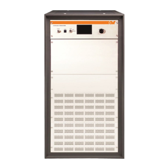
1200 watts of swept power covering the frequency range from 0.01 to 100MHz, derating to 1100 watts from 100 MHz to 225 MHz. The Model 1200A225 is housed in a single stylish contemporary equipment cabinet. -
Page 20: Power Supplies
Model 1200A225 POWER SUPPLIES The Model 1200A225 is a modular design with each section having self-contained power supplies. These power supplies are self-contained, regulated switching units. The Main Power Amplifier (MPA) unit has a supply providing +42V as the main source of power for the amplifier circuitry. -
Page 21: Installation
Select an operating location that will permit free air circulation around the amplifier’s cabinet. The Model 1200A225 utilizes air cooling and should be located where the normal flow of air into or exiting from the unit will not be restricted, diverted, or re-circulated through the unit itself. For example, do not position the unit next to a wall or other equipment that would cause a restriction of airflow into or out of the unit. -
Page 22: Driver Output Cables
Due to the variety of power systems available, line cords are not shipped with this unit. The user must install the recommended supply line in the unit. The Model 1200A225 requires a line cord having #8AWG or larger conductors. To install the line cord, referring to Figure 1-1, remove the power distribution box cover, located at the middle of the cabinet, in the rear. -
Page 23: Amplifier Input Connector
They are normally used for operating external power meters. A calibration table is provided with the Model 1200A225 that provides a list of external RF power meter offset values. The offset values completely characterize the directional coupler/forward sample port circuit attenuation across the frequency band, and are available in electronic form. - Page 24 Model 1200A225 Rev C...
-
Page 25: 1200A225 Ac Line Cord Installation
Specifications Features 1200A225 The Model 1200A225 is a solid-state, self- play to indicate the operate status and fault contained, broadband amplifier designed for conditions if an over-temperature or power 1200 Watts CW applications where instantaneous bandwidth, supply fault has occurred. The unit can be re- ... -
Page 26: 1200A225 Connector Locations (Rear View Left, Front View, Right)
HARMONIC DISTORTION: Minus 30 dBc typical, mi- nus 20 dBc maximum at 750 watts SPURIOUS: Minus 70 dBc typical PRIMARY POWER: 200-240 VAC single-phase, 50/60Hz, 4.6 kWatts Ordering Options Contact your AR RF/Microwave Instrumentation Sales Associate for specific model configuration pricing. -
Page 27: Safety Interlock Connector
Page 3 Graphs 1200A225 1200 Watts CW 10kHz–225MHz... - Page 28 Page 4 Graphs 1200A225 1200 Watts CW 10kHz–225MHz...
- Page 29 Page 5 Envelope Drawing 1200A225 1200 Watts CW 10kHz–225MHz To order AR Products, call 215.723.8181. For an applications engineer call:800.933.8181. Direct to Service call: 215.723.0275 or email: service@arworld.us For Faxing Orders:866.859.0582 (Orders Only Please) info@arworld.us Approved for public release by AR RF/Microwave Instrumentation...
-
Page 31: Operating Instructions
CONTROL AND INDICATOR FUNCTIONS The Model 1200A225’s front panel is shown in Figure 2-1; the unit’s rear panel features are detailed in Figure 2-2. Figure 2-1 Digital Control Panel (DCP) Features... -
Page 32: Interface Identification And Diagrams
15-pin DIN Contactor Interlock Type BNC Fwd/Rev Coupled Input Type BNC INTERFACE IDENTIFICATION AND DIAGRAMS Electrical Power RF Signal Input 1200A225 Amplifier RF Signal Output Local Control Panel Remote I/O Ports Figure 2-3. Model 1200A225 Interface Block Diagram Rev C... -
Page 33: Rf Input
Inhibit. The Local option allows for control of the Model 1200A225 using the control panel located on the front of the unit. The Remote option allows for control of the Model 1200A225 using any of the remote (I/O) ports found on the rear of the unit. -
Page 34: Local Control Interface
2.4.1.2 Power Button The momentary POWER button turns the main power to the Model 1200A225 on and off. The status of the green light-emitting diode (LED) in the switch indicates whether the Model 1200A225’s power is on or off. The main power supply fans are active when power is on. The LCD touch display is active as long as the main circuit breaker for the Model 1200A225 power entry module is on. -
Page 35: Inhibit Screen
Inhibit Screen The Inhibit screen is used as an indication to the user that the Model 1200A225 is in an inhibited mode. In Inhibit Mode, the POWER button cannot be used, and no touch screen menu options are available. In addition, the ADJUST knob is disabled. -
Page 36: Main Menu Screen
At the bottom of the screen are the forward and reverse power indicator bar graphs and associated values in Watts. The scale of the bar graphs is based on a range of 0 to rated power. For the Model 1200A225 rated power is 2500Watts. -
Page 37: Select Screen
Model 1200A225 2.4.1.5.3 Select Screen The Select screen is the same as the Main Menu screen with the exception of the menu options. The menu options in this screen allow the user to select what parameter the ADJUST knob can adjust. Once a selection is made, the screen will automatically change back to the Main Menu screen. -
Page 38: User Screen
Model 1200A225 2.4.1.5.5 User Screen The User screen presents the user with the revision levels of all the firmware that is running on all the main control system components. For the Switch Breakout Board (SBB) assemblies, only the piggy-back assembly firmware is listed. -
Page 39: I/O Screen
Model 1200A225 2.4.1.5.7 I/O Screen The I/O screen is used to present the user with menu options pertaining to the remote I/O ports found on the rear of the unit and the interaction with the touch screen. These options include the GPIB address, RS- 232/Fiber-Optic Serial Baud Rate, and key beep. -
Page 40: Rs-232/Fiber-Optic Serial Baud Rate Screen
Model 1200A225 2.4.1.5.9 RS-232/Fiber-Optic Serial Baud Rate Screen The RS-232/Fiber-Optic Serial Baud Rate screen is used to select the baud rate used by both the RS-232 port and the Fiber-Optic Serial port. A thin black outline indicates the present baud rate selection. When the back button is pushed the baud rate selection is stored to non-volatile memory. -
Page 41: Remote Screen
Model 1200A225 2.4.1.5.11 Remote Screen When the Keylock switch is set to the REMOTE position the Remote screen appears. This screen has all the same information as the Main Menu screen except that the blue bar graph and associated value are only for the RF Gain value. -
Page 42: Remote Control Interface
Communicating through two or more ports at one time will cause data collisions and lost commands or queries. The Keylock switch on the control panel of the Model 1200A225 allows it to be controlled using remote communications. All remote queries will work in any Keylock switch position, but all remote commands will only work when the position is set to REMOTE. -
Page 43: Fiber-Optic Serial Communication
The Fiber-Optic port provides the user with the ability to optically isolate the controlling PC from the Model 1200A225. This can be useful in an environment where RF/Microwave energy could be coupled onto a connection to one of the “wired” communications ports and fed back to the controlling PC. -
Page 44: Usb Communication
This port can be used in conjunction with either an AR Model IF7000 RS-232 to Fiber-Optic Interface (1200 to 9600 baud only) or an AR Model IF7001 USB to Fiber-Optic Interface (19200 baud only). Note that these devices use SMA connectors so a fiber-optic cable is needed with ST connectors on one end and SMA connectors on the other. -
Page 45: Remote Commands
An application program on the computer/controller should issue only one character string (command or query) at a time. After each functional command is issued, the Model 1200A225’s status should be checked to ensure that the command has been properly executed. The application program should allow sufficient time for the function to be completed before checking the status. -
Page 46: Power On/Off
Model 1200A225 Table 2-4. Relationship between the Model 1200A225 Controls and Remote Communication AC Power and Power Keylock Switch Remote Circuit Breaker Communication INHIBIT LOCAL REMOTE Command Query √ √ √ √ √ √ √ √ √ √ √ √... -
Page 47: Reset Faults
Response Format: None (No query for this command) Example: To clear any faults, send the following command: RESET<LF> 2.4.2.6.4 Mode Select This command sets the ALC mode of the Model 1200A225. Syntax: MODE:x Parameters: Mode(x): MANUAL = Set to Manual/CW mode ALC<space>INT = Set to ALC Internal mode... -
Page 48: Identity
Response Format: f,m,n,<LF> Where: f = manufacturer m = model designation n = firmware revision Example: To get the identity of the Model 1200A225, send the following command: *IDN?<LF> Response: AR-RF/MICROWAVE-INST,1200A225,1.0<LF> 2.4.2.6.7 IO Board Firmware Revision Query to get the firmware revision of the I/O Board. -
Page 49: Machine State
Model 1200A225 2.4.2.6.8 Machine State This query reads the RF gain, detector gain, ALC threshold, and ALC response time of the Model 1200A225. MSB? Syntax: Parameters: None Query only (always requires a ? character) Response Format: RF<space>GAIN=x, DT<space>GAIN=x, THRES=x, RESP=y<LF>... -
Page 50: State
They can be 0 to 9 or A to F. Each hexadecimal character represents a 4-bit binary number. This 4-bit number is a bit pattern which contains information about the state of the Model 1200A225. definitions of these bit positions can be found in the table below. -
Page 51: Forward Power
Model 1200A225 2.4.2.6.10 Forward Power Query to get the forward power. FPOW? Syntax: Parameters: None Response Format: FPOW=x<LF> Where: x = 0 to 99999 Values are corrected and linearized. They can be up to five digits in length. Leading zeros are read as spaces. -
Page 52: Rf Gain
RFG? Parameters: None Response Format: RFG=<space>x<LF> Where: x = 0000 to 0100 Example: To find out the RF gain of the Model 1200A225, send the following query: RFG?<LF> RFG=<space>0075<LF> Response: (75% Gain) 2.4.2.6.13 Faults Query to find the faults that have occurred with the Model 1200A225. -
Page 53: Operating Hours (Rf On)
Model 1200A225 2.4.2.6.14 Operating Hours (RF On) Query to get the RF On operating hours. Syntax: Parameters: None Response Format: OH=x<LF> Where: x = 0 to 100000 Units are Hours. Values can be up to six digits in length. Leading zeros are read as spaces. -
Page 54: Query Mpa Coolant Temperature And Transistor Currents
Model 1200A225 Parameters: Where n is the two digit MPA number which can only be 01. Response Format: None (No Query for this command) Example: To initiate the process of finding out the coolant temperature and transistor currents for MPA 1, send the following command: MPA01<LF>... -
Page 55: Alc Board Firmware Revision
Model 1200A225 Parameters: x = 0 to 500 in seconds Query: ROPTO? Response Format: ROPTO=x<LF> Example: To set the required period between communications that must be maintained once RF On has been initiated, send the following command. ROPTO10<LF> To find out what the period between communications that must be maintained once RF On has been initiated, send the following query. -
Page 56: Sbb (Piggyback) Firmware Revision
Model 1200A225 2.4.2.6.20 SBB (Piggyback) Firmware Revision Query to get the firmware revision of the piggyback SBB assembly. *SBB? Syntax: Parameters: None Query only (always requires a ? character) Response Format: SBB_SW_REVx<LF> Where: x = firmware revision Example: To get the firmware rev. of the piggyback SBB assembly, send the following command: *SBB?<LF>... -
Page 57: System Serial Number
Model 1200A225 2.4.2.6.22 System Serial Number Query to get the serial number of the system. Syntax: Parameters: None Query only (always requires a ? character) Response Format: x<LF> Where: x = serial number (6 to 8 characters) Example: To get the serial number, send the following command: SN?<LF>... -
Page 58: Interlocks
To set the default mode to manual, send the following command: DEFAULT:MODE:MANUAL<LF> 2.4.2.7 Interlocks The Model 1200A225 has two separate interlock circuits that are wired to the rear panel Safety Interlock connector. Both interlocks require normally closed external circuits to allow the amplifier to function. 2.4.2.7.1 Inhibit Interlock... -
Page 59: Rf Output
Model 1200A225 RF OUTPUT The output of the Model 1200A225 is provided through a male 7-16 DIN Female RF connector located on the rear of the unit. ELECTRICAL POWER There is one power connection for the Model 1200A225. It requires a single-phase, 200–240 VAC connection (50/60 Hz, 4.6kW maximum). - Page 60 Model 1200A225 Rev C...
-
Page 61: Theory Of Operation
3. THEORY OF OPERATION GENERAL The Model 1200A225 amplifier can be a relatively simple unit to understand. The amplifier chain is a straightforward design, with a few control elements in the lineup. The unit’s power supply, control and fault detection circuits can be easily understood by anyone with a minimal understanding of analog and digital circuitry. -
Page 62: A5 Control/Fault Board (Schematic #10030013)
MPA. The total output of the four modules in combination is sufficient to meet the specified output power of the 1200A225. Primary power to the MPA is from the AC power distribution unit. It is switched by the breaker on the MPA rear panel, as well as the contactor internal to the MPA which is controlled from the driver/control unit. -
Page 63: Liquid-Cooled Module
Model 1200A225 3.2.8 Liquid-Cooled Module The Liquid-cooled module (schematic 10038146) consists of two pair of push-pull transistors, for a total of four transistors (Q1-Q4). The transistors are mounted on a copper plate through which liquid coolant is circulated. Transistor bias is set and controlled by the automatic bias board which plugs into the module. The... -
Page 64: Control Circuits
3.4.1 Fiber-Optic System Control Link The 1200A225 control system uses a fiber-optic communication system to link each of the MPA’s back to the Driver/Controller unit. The Digital Control Panel (DCP) uses this link to send information to the system MPA’s and read fault conditions. Therefore, this link is critical to the operation of the amplifier system. -
Page 65: Automatic Level Control Circuits
Model 1200A225 Note that in order to complete the circuit through K1, the external AC interlock circuit must be closed. The I/O panel Safety Interlock connector provides pins 10 and 14 for this purpose. Another interlock circuit, provided in the same connector, is used for RF inhibit, pins 1 and 8, if the user so desires. Both types can be used simultaneously in their respective circuits. -
Page 66: Fault Detection Circuits
Model 1200A225 FAULT DETECTION CIRCUITS This section describes the function and theory of the Model 1200A225’s fault detection circuits. The driver power module A1 is monitored for over-temp fault using a thermal switch. In the event of an over- temp, the PS2 power supply will be shut down so no DC is supplied to the A1 module. -
Page 67: Under-Current
PS1. 3.5.5 Interlocks The Model 1200A225 Driver has two interlocks that are wired to the rear panel Safety Interlock connector. The interlocks are separate circuits. Both interlocks require normally closed external circuits to allow the amplifier to function. 3.5.5.1... -
Page 68: System Error (F/O Link Fault)
Model 1200A225 is set to REMOTE). Either of these conditions causes the 1200A225’s DCU to return to normal conditions. Forcing the user to reassert the Operate command (RF On) after a fault or interlock condition is a safety feature that prevents an unexpected burst of RF when the fault or interlock condition has been restored. Fault conditions that require the MPA to be disconnected from the AC mains will be reset automatically upon re- energizing the amplifier. -
Page 69: Troubleshooting And Repair
4. TROUBLESHOOTING AND REPAIR 4.1. GENERAL Because it is a relatively simple instrument, the Model 1200A225 should require very little maintenance. It is built with solid state devices and printed wiring boards (PWBs) that should ensure long, trouble-free life. Should trouble occur, special care must be taken when servicing the unit to avoid damaging the solid state devices and PWBs. -
Page 70: Power Supply Faults
Model 1200A225 4.3.2 Power Supply Faults Indication – PS2 The main power supply has failed to produce DC voltage within the design range of the power supply. The main power supply PS2 is located on the bottom shelf of the MPA. -
Page 71: Fault Troubleshooting Guide
Model 1200A225 4.3.6 Fault Troubleshooting Guide Driver Fault Type of Fault Possible Reasons Therm driver Thermal Driver fan blocked or clogged, PS2 has no output UC driver A3 Under Current Driver FET is damaged and drawing no current, Gate voltage is being pulled down Driver FET had been over driven. -
Page 72: Diagnosing And Replacing Amplifier Modules
Model 1200A225 DIAGNOSING AND REPLACING AMPLIFIER MODULES 4.4.1 Locating Modules See Figure 4-1. Figure 4-1. 1200A225 MPA/Module Locations (Rear View) Rev C... -
Page 73: Module Replacement
Model 1200A225 4.4.2 Module Replacement If, after troubleshooting, it has been determined that one of the Liquid-cooled modules has failed, the following procedure should be followed if a spare module for the unit is available. CAUTION: Power to the unit must be turned off before performing any repair work;... - Page 74 Model 1200A225 Rev C...
-
Page 75: Appendix A. Installing Software Upgrades
Driver Box. 6. When the utility confirms that the 1200A225 is in the correct state, it will prompt for the model specific firmware file which was unzipped in the steps above. Select this file and allow the utility to complete the update process. -
Page 76: I/O - Input Output Board Assembly Firmware (X1)
4. Run the AR Firmware Upgrade Utility and follow the instructions it provides. When asked to power on the device, only power on the Driver Box. 5. Once the utility successfully connects to the 1200A225 Driver Box, click the Update button for the I/O firmware. -
Page 77: Breakout - Fiber-Optic Connected Switch Breakout Board (Sbb) Assembly Firmware In Mpas (X4)
Do not change the names of the folder or files that are unzipped. 6. Run the AR Firmware Upgrade Utility and follow the instructions it provides. 7. Once the utility successfully connects to the 1200A225, double click the 1200A225 model number in the upper right corner of the utility. -
Page 78: Assemblies That Require Physical Replacement To Update Firmware
Model 1200A225 8. The utility will prompt for the ALC firmware file which was unzipped in the steps above. Select this file and allow the utility to complete the update process. A.7 ASSEMBLIES THAT REQUIRE PHYSICAL REPLACEMENT TO UPDATE FIRMWARE The following assemblies can only have their firmware updated by swapping physical assemblies: •... - Page 79 These modules are not field-repairable and should never be opened outside of AR’s Microelectronics Lab. The modules in these product lines have a security label on two sides of the modules between the housing and lid/cover. If the security label is removed and or cut, the warranty of the module will be voided.
Need help?
Do you have a question about the 1200A225 and is the answer not in the manual?
Questions and answers