Table of Contents
Advertisement
Quick Links
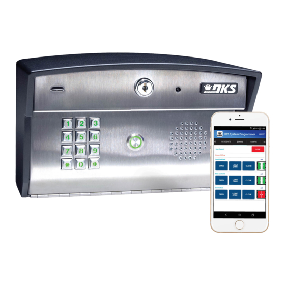
Installation/Owner's Manual
Internet/Cellular Programmable Video Telephone/Access Control System
Use this manual for circuit board 8863-010 Revision C or higher.
1 1
2 2
4 4
3 3
5 5
7 7
6 6
8 8
9 9
0 0
S u
r f a
c e
M o
u n
t
Download the smart phone App at:
Android-version 8 or higher OR iphone 6-with IOS 9 or higher
Date Installed:
Installer/Company Name:
Phone Number:
Leave Manual with Owner
UL Listed
Circuit Board
Serial Number
and Revision Letter:
Register and Program your Entry System at:
https://dksti.com
Copyright 2021 DoorKing
®
, Inc. All rights reserved.
Control a main door / gate and two other entry points
F l u
s h
M o
u n
t
Copyright 2009 DoorKing, Inc. All rights reserved.
Model 2112
Model 2112
Model 2112
2112-065-G-12-21
1 1
2 2
4 4
3 3
5 5
7 7
6 6
8 8
9 9
0 0
Advertisement
Table of Contents

Related Manuals for DoorKing 2112


Summary of Contents for DoorKing 2112
- Page 1 Installer/Company Name: Circuit Board Serial Number Phone Number: and Revision Letter: Leave Manual with Owner Register and Program your Entry System at: https://dksti.com Copyright 2021 DoorKing ® , Inc. All rights reserved. UL Listed Copyright 2009 DoorKing, Inc. All rights reserved.
- Page 2 2112-065-G-12-21...
-
Page 3: Features
Kiosk DoorKing, Inc. reserves the right to make changes in the products described in this manual without notice and without obligation of DoorKing, Inc. to notify any persons of any such revisions or changes. Additionally, DoorKing, Inc. makes no representations or warranties with respect to this manual. This manual is copyrighted, all rights reserved. -
Page 4: Specifications
9.25” Flush Box Rough-In Box 4.25” 4.5” 12” 10” 3.5” Flush Box .875” Dia F l u 5” 2.5” Bottom Views - I n 10.25” u g h 3.5” Rough-In Box 1.25” Dia 5” 2.625” Specs - 2 2112-065-G-12-21... -
Page 5: Table Of Contents
1.3 Mount the 2112 Remove Control Board and Faceplate 2112 Surface Mount Configurations 2112 Flush Mount 2112 Flush Mount in a DoorKing Self-Standing Lighted Kiosk SECTION 2 - WIRING 2.1 Terminals TB1, TB2, TB3, TB4 2.2 Raspberry Pi 3 Model B Audio/Video Board 2.3 Grounding and Surge Suppression... -
Page 6: Important Notices Fcc - United States, Doc - Canada
DOC Registration Number: 1736 4507 A Notice: DoorKing does not provide a power transformer on units sold into Canada. Use only transformers that are CSA listed to power the telephone entry system. The model 2112 requires a 16.5-volt, 20 VA transformer. -
Page 7: General Information Installation Guidelines And Safety Information
Instruct the end user to read and follow these instructions. Instruct the end user to never let children play with or operate any access control device. This Owner’s Manual is the property of the end user and must be left with them when installation is complete. 2112-065-G-12-21... -
Page 8: Section 1 - Installation
Note: DoorKing cannot replace this specific lock or keys if lost. 1.1 Standard Internet Installation ONLY A Cat5 wire will need to be run to the 2112 installation location that is ALREADY connected to the internet, then installation can begin. Typical Internet Source... -
Page 9: Mount The 2112
1.3 Mount the 2112 Use the specification dimensions page in front of manual and the next 2 pages to help with the installation of your chosen 2112 model. Remove Control Board and Faceplate The control board removal is the same for flush mount model. -
Page 10: 2112 Surface Mount Configurations
NOT make a good Cellular connection, see ground. sections 1.1 and 1.2). TIP: The mounting height of the 2112 will determine the Add washers on field-of-view of the video lens. High profile vehicles may bottom to angle the present a problem when viewing the person inside the vehicle unit upward (see Tip). -
Page 11: 2112 Flush Mount
F l u 7 . 5 ” h - I ” 4 . 5 . 2 5 ” IMPORTANT Choose how your u i t 2112 will function (Internet or Cellular connection, see sections 1.1 and 1.2). 2112-065-G-12-21... -
Page 12: 2112 Flush Mount In A Doorking Self-Standing Lighted Kiosk
2112 Flush Mount in a DoorKing Self-Standing Lighted Kiosk ONLY the flush mount can be installed into the self-standing kiosk Bolt flush box into the (P/N 1200-175). rough-in box with 4 Secure the rough-in box in the kiosk. Run all necessary wires to supplied bolts. -
Page 13: Section 2 - Wiring
DO NOT power strikes or The 2112 operates ONLY on 16.5 VAC. magnetic locks from the 2112 power DO NOT power the 2112 with 24 Volt transformer. It is recommended to keep transformer or source voltage. power wire runs as short as possible. -
Page 14: Raspberry Pi 3 Model B Audio/Video Board
Low Voltage Surge Suppressor Surge suppressor within 10 ft of 2112. It is highly recommended that a low voltage surge suppressor (DoorKing P/N 1878-010) be installed to help protect the telephone entry system from power surges. 1878-010 POWER LINE 2112... -
Page 15: Section 3 - Register / Programming / Volume Adjust
3.1 Register 2112 After the 2112 is connected to the internet (Cat5 connection or cellular module), go to DoorKing's website: https://dksti.com to register the 2112. The System ID Number will be needed for registering, found inside the 2112. Click on the REGISTER button and fill out the necessary fields on the page. A confirmation e-mail will be sent to you after completing the registration page successfully. -
Page 16: 2112 Wiring Schematic
2112 Wiring Schematic Blue end MUST be inserted on LEFT side of video connector as shown. L i f s t o V i d R i b Video 1894-041 Lighted Keypad Wire Right POT 2 POT 1 MIC OUT 1... - Page 17 2112-065-G-12-21...
- Page 18 Installation/Owner’s Manual Model 2112 Model 2112 Model 2112 Internet/Cellular Programmable Video Telephone/Access Control System Use this manual for circuit board 8863-010 Revision C or higher. 2112-065-G-12-21 Control a main door / gate and two other entry points Download the smart phone App at:...
Need help?
Do you have a question about the 2112 and is the answer not in the manual?
Questions and answers