Table of Contents
Advertisement
Quick Links
Advertisement
Table of Contents

Related Manuals for Axis FA Series


Summary of Contents for Axis FA Series
- Page 1 OPERATION MANUAL FORCE GAUGE FA Series File: 2012-05-25 FA-140 FA0021 GB...
-
Page 2: Table Of Contents
OPERATION MANUAL Contents: Introduction _____________________________________________________________________ 3 Basic Set _______________________________________________________________________ 3 Safety instructions ________________________________________________________________ 4 3.1 Main safety rules ________________________________________________________________ 4 3.2 Safety rules during measurements above 1kN (about 100kg) ______________________________ 4 Rules for handling a worn force gauge ________________________________________________ 5 Technical data ___________________________________________________________________ 6 Keys and indicators _______________________________________________________________ 8 Preparing the force gauge for operation _______________________________________________ 9... -
Page 3: Introduction
OPERATION MANUAL 1. Introduction The FA series force gauges are designed for measuring pressure or pulling force in laboratory, manufacturing and quality control applications. Measurements up to 200N are executed by holding the gauge in hand. Measurements from 200N to 500N require using a double-hand handle (additional equipment). -
Page 4: Safety Instructions
OPERATION MANUAL 3. Safety instructions 3.1 Main safety rules Read carefully the safety instructions included below. Observe these instructions to avoid electrocution or damage to the force gauge itself or other devices connected to the force gauge. • Repairs and any necessary adjustments may only be conducted by qualified personnel. -
Page 5: Rules For Handling A Worn Force Gauge
OPERATION MANUAL from one side and the other side of the sensor must have adequate strength, as evidenced by a proper certificate. Exploitation • On the basis of this force gauge manual, a whole measurement system manual should be developed by user. Measurement system manual should be available on the measurement post during exploitation. -
Page 6: Technical Data
OPERATION MANUAL 5. Technical data Type FA50 FA200 FA500 Maximum force measured 50N (~5kg) 200N (~20kg) 500N (~50kg) Reading graduation (d) 0,01N (1g) 0,05N (5g) 0,1N (10g) ±0,05% Accuracy Measurement units N, g, lb, oz, kg Maximum overload Operating temperature -10 ÷... - Page 7 OPERATION MANUAL Type FA50k FA100k FA200k 50kN 100kN 200kN Maximum force measured (~5t) (~10t) (~20t) Reading graduation (d) 10N (1kg) 20N (2kg) 50N (5kg) ±0,05% Accuracy Measurement units N, g, lb, oz, kg Maximum overload Operating temperature -10 ÷ 40°C Internal resolution 24 bits (16mln graduation) Process speed...
-
Page 8: Keys And Indicators
OPERATION MANUAL Keys and indicators Main keys: ON/OFF ON / OFF key (standby), UNIT/CLEAR Change units / cancel selection or change a parameter value, BACKLIGHT Turn on illumination (ECO mode), ENTER Confirm / select an option or a digit, (→0←) Zeroing / resetting (entering the current reference value to be subtracted from the measured values in each consecutive measurement) Navigation keys:... -
Page 9: Preparing The Force Gauge For Operation
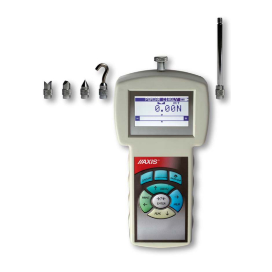
- tip A – measurement of surface pressure force, - tip B – measurement of point pressure force, - tip C – measurement of pressure on an axis or an edge, - tip D – measurement of edge pressure force, - tip E –... - Page 10 OPERATION MANUAL Force gauges with a range from 1kN to 20kN are equipped with an external force sensor connected by a rod with a plug. Bearings are connected to the extensometric force gauge in order to avoid unwanted stress when mounting load.-{}- The meter is delivered in two carrying cases (separate for the meter and for the sensor).
-
Page 11: General Rules For Use
1. When conducting measurements by hand, make sure that the direction of the measured force is identical with the gauge’s axis (axis of the gauge plunger). Otherwise, only a component force along the gauge’s axis will be measured. -
Page 12: Turning On The Gauge
9. Turning on the gauge Place the gauge in the operating AXIS position, e.g. horizontal position (by laying it on a table). Turn on the AXIS Sp. z o.o. gauge by pressing the key. ON/OFF ul. Kartuska 375B 80-125 Gdańsk When necessary, plug the gauge’s... -
Page 13: Description Of Measurement Methods
OPERATION MANUAL 10. Description of measurement methods The gauge can be used to measure pressure and pull forces. In addition, when mounted properly, it can be used as suspension scales to measure the mass. 10.1 Measuring actual and peak value of a pressure/pull force Measuring pressure force Measuring pull force Measuring pull force external load cell vertion... - Page 14 OPERATION MANUAL Before starting the measurement, choose a suitable measurement tip, screw it to the gauge plunger and reset the gauge in the operating position, e.g. horizontal position (laying the gauge on a table). The resetting process starts automatically after →T(0)←...
-
Page 15: Force Characteristics Measurement, Measurement Registration To Memory
OPERATION MANUAL 10.2 Force characteristics measurement, measurement registration to memory In order to enable changing force measurement and to create results visualizations (graphs or histograms), force gauge is equipped with actual results buffer memory and a memory that holds up to 8 files with measurement results. Detailed description of available options can be found in 13.1 chapter. -
Page 16: Measurement Of The Mass - Using The Gauge As Scales
5kg will indicate 5,000kg, but when it will be moved to Katowice (50° 15′ N, h=250m above sea-level.) it will indicate 4,998kg. The factory preset value is the gravitational acceleration in AXIS headquarters location ( ). When using force gauge as a balance in place with = 9.81415 m/s... - Page 17 OPERATION MANUAL Measurement Measurement using a gauge using a hand-held gauge mounted on a stand (stand available on request) Suspended weight measurement (suspension element available on request)
- Page 18 OPERATION MANUAL Screw the hook tip to the gauge plunger, suspend a bowl on the hook and place the gauge in the operating position (as shown in the figure). The display’s indications will rotate by 180 USER’s MENU To change force units to mass 1.
-
Page 19: Connecting External Devices
OPERATION MANUAL 11. Connecting external devices The force gauge is equipped with a socket for an external power supply unit and RS232C serial connector for a printer or a computer. ZASILACZ RS232C masa ZASILACZ POWER SUPPLY UNIT masa Description of the data transmission protocol when working with a computer (LonG): The scales transmit the result as follows (8 bits, 1 stop, no parity, 4,800 bps): Computer→Gauge: initiating signal S I CR LF (53 h 49 h 0Dh 0 Ah),... -
Page 20: User's Menu
OPERATION MANUAL 12. User’s Menu The User’s Menu includes all functions and options necessary to operate the gauge or extend its functionalities. USER’s MENU To use the options of the USER’s 1. Applications , use the Move the MENU MENU 2. -
Page 21: Data Stored
OPERATION MANUAL 13.1 Data stored application allows for the following: Data memory - presentation of the collected measurements, saving, reading, erasing memory Statistics), - selecting the mode for collecting data, - exit. USER’s MENU 1. Applications Move the cursor to Applications and 2. - Page 22 Statistics data: – transmission to a printer, PRINT> < < – bar graph, HISTOGRAM> – graph with a time axis. GRAPH> < USER’s MENU 1. Applications Move the cursor to Applications and 2. Units press ENTER 3.
- Page 23 OPERATION MANUAL Save, read, erase memory (Statistics) option allows for the following: Statistics – saves the data currently presented, SAVE > < – reads a file from the memory, < READ > – erases the data currently presented, < RESET > –...
-
Page 24: Comparison With Threshold Values Min / Ok / Max
OPERATION MANUAL 13.2 Comparison with threshold values MIN / OK / MAX This selection includes the following functions to effectively assist you with the measurement: - memory operations and data analysis, - comparison with two threshold values (MIN / MAX). USER’s MENU 1. -
Page 25: Units
OPERATION MANUAL 14. Units Basic measurement unit for force gauge is 1N (force in SI unit) The following units are available to the user: - kilogram (kg) 1kg ≈ 9,81415N - Pound: 1 lb = 453.592374 g - ounce: 1 oz = 28.349523 g - Newton: 1 N = 0.10197 kg (starting from FA0021 program version): - kilogram-siła (kgf): 1kgf=9,80665N... -
Page 26: Configuration
OPERATION MANUAL 15. Configuration This selection includes all options for setting the gauge’s modes of operation. USER’s MENU 1. Applications Move the cursor to Configuration 2. Units and press ENTER 3. Configuration 4. Calibration 5. Info 6. Exit CONFIGURATION 1. Measure speed Move the cursor to the desired 2. -
Page 27: Auto-Zeroing
OPERATION MANUAL 15.2 Auto-zeroing When activated, this option automatically maintains zero indications on the gauge, if the gauge’s sensor is not affected by any external force or if the zero indication → ← was produced by pressing the key. The range of values (calculated in the gauge’s reading graduation near zero) subject to the reset must be entered under option (2 digits). -
Page 28: Print Settings
OPERATION MANUAL 15.3 Print settings According to the requirements of GLP procedures, it is possible use an external printer to produce print-outs from the gauge including text information. USER’s MENU Use the navigation keys and to select ENTER Print settings 1. -
Page 29: Setting Parameters For Serial Connectors
OPERATION MANUAL 15.4 Setting parameters for serial connectors The parameters of the serial connector must be suitable for the device receiving the signal. USER’s MENU Parameters to be set: 1. Applications - Baudrate – transmission and 2. Units receiving rate (4,800 ÷ 115,200 3. -
Page 30: Lcd Settings
OPERATION MANUAL 15.5 LCD settings This option adjusts the gauge’s display to external lighting conditions. USER’s MENU 1. Applications 2. Units Use the navigation keys and 3. Configuration to select 4. Calibration ENTER LCD settings. Next, use →, ← and 2. -
Page 31: Selecting The Menu Language
OPERATION MANUAL 15.6 Selecting the menu language Three menu languages are available: <PL> – Polish, <ENG> – English, <DE> – German, <ESP> - Spanish. USER’s MENU Use the navigation keys and 1. Applications to select ENTER Language. 2. Units select one of the available menu 3. -
Page 32: Setting Date And Time
OPERATION MANUAL 15.7 Setting date and time This option is used for entering the current date and time. Access to this setting is secured by the PIN code. USER’s MENU Use the navigation keys and to select If a ENTER Date and time. -
Page 33: Turning The Sound On/Off When Using The Keypad (Beep)
OPERATION MANUAL 15.8 Turning the sound ON/OFF when using the keypad (beep) This options turns ON or OFF the sound signalling that a key on the keypad has been pressed. When the sound is turned on, the user usually does not apply excessive force when pushing the keys. -
Page 34: Automatic Power Off (Auto-Off)
OPERATION MANUAL 15.9 Automatic power OFF (Auto-OFF) This option allows for an automatic cut-off of the gauge’s power supply to save the battery’s energy. USER’s MENU Use the navigation keys and 1. Applications to select ENTER Auto-OFF 2. Units and one of the following 3. -
Page 35: Monitoring The Batteries' Charge Level (Battery)
OPERATION MANUAL 15.10 Monitoring the batteries’ charge level (Battery) This option is used for reading the charge level of the batteries and allows for the charging to be turned off to protect ordinary batteries, if such batteries are used instead of rechargeable batteries. Charging ordinary batteries used instead of rechargeable batteries may lead to major damage to the gauge. -
Page 36: Firmware Update
6. Calibration 7. Exit After setting force gauge into CONFIGURATION update mode (sign Firmware update displayed) turn on AXIS . . . Loader computer program and 7. Date and time follow the instructions in program 8. Auto-OFF 9. Battery manual. -
Page 37: Reset Settings
OPERATION MANUAL 15.12 Reset settings This option restores factory settings (default settings) for all options. USER’s MENU Use the navigation keys and 8. Applications to select ENTER Reset settings 9. Units the option 10. Configuration YES. 11. Calibration 12. Exit As a result of restoring factory CONFIGURATION settings, the gauge will reset and... -
Page 38: Calibration
OPERATION MANUAL 16. Calibration To calibrate the gauge, select the method of applying load. For this purpose, use a stand or suspend a standard of mass on the gauge. Reset the gauge without load using → ← key. Use the navigation keys and USER’s MENU to select ENTER... -
Page 39: Maintenance, Troubleshooting And Repairing Minor Types Of Damage
OPERATION MANUAL 17. Maintenance, troubleshooting and repairing minor types of damage 1. Keep the gauge clean. 2. When using the force gauge, make sure that no contamination gets between the gauge plunger and the enclosure. Upon identifying any contamination, remove it using a tool which does not conduct electricity. -
Page 40: Force Gauge Menu Diagram
OPERATION MANUAL 18. Force gauge menu diagram Menu Data stored Count Applications Stats Total Direct acces keys: Average CLEAR St.dev. Rel.dev. <PRINT><HISTOGRAM><CHART><SAVE><LOAD><RESET><DELETE><EXIT> <FILE01> <FILE01> <FILE01> <FILE02> <FILE02> <FILE02> ..<FILE08> <FILE08> <FILE08> Mode <MANUAL>... - Page 41 OPERATION MANUAL Interface Baudrate <4 800-115 200> Bits <7>< 8-bit> Parity <none><even><odd> Sending <NORMAL><NO STB><AUTOSTB> <CONTIN.> Exit LCD settings Contrast Backlig. <ON><OFF><ECO><BAT> Direct. <AUTO><UP><DOMN> Time LCD <OFF><ON> Exit Language <PL><ENG><DE><ESP> Time Time&Date Date 1234 12/24 <12H><24H> Format <YYYY-MM-DD><MM-DD-YYYY><DD-MM-YYYY>> Exit Keyboard Beep <ON><OFF>...
-
Page 42: Declaration Of Conformity
OPERATION MANUAL Declaration of Conformity AXIS Spółka z o.o. 80-125 Gdańsk, ul.Kartuska 375B confirm with all responsibility that force gauges: FA50, FA200, FA500, FA1k, FA2k, FA5k, FA10k, FA20k, FA50k, FA100k i FA200k marked with CE mark comply with the following: 1. - Page 43 OPERATION MANUAL Appendix A FA00 meter with external sensor 1. General description FA00 force gauge requires joining the force sensor by using connector situated in meter housing. Moreover it is crucial to set force gauge working parameters. After this actions earlier chapters of the manual are applied. 2.
- Page 44 OPERATION MANUAL 4. Meter calibration FA00 meter calibration method doesn’t differ from the description in 16 chapter - Calibration. Calibration weight value must respond to force gauge parameters.
- Page 45 OPERATION MANUAL Notes...
- Page 46 OPERATION MANUAL...
Need help?
Do you have a question about the FA Series and is the answer not in the manual?
Questions and answers