Advertisement
Quick Links
Model #
1034- -290
Assembly Instructions
For immediate help with assembly, or
for additional product information,
call our toll-free number:
Mon-Fri - - 7am-11pm, Sat - - 9am-5pm ET
United States and Canada (except holidays)
Our highly trained Customer Service
staff is ready to provide friendly
assistance. And, if a part is damaged or
missing, most replacements ship from
our facility in one to two business days.
Lot #: 1510340
Date Purchased:
Record the date you
purchased this unit and
save the booklet for
future reference.
If you ever need to
contact Sauder about this
unit, refer to the lot #
and the model # when
calling our toll-free
number. Or write to:
Sauder Woodworking
P. O. Box 156
Archbold, OH 43502.
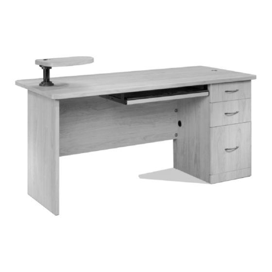
Computer Workcenter
(Desk)
Notice
This instruction booklet contains important
safety and warranty information. Please read
and keep for future reference.
Don't miss out on your opportunity to enter the $100,000
Give Away. Simply fill out the Product Registration and
Warranty Confirmation card found in the center section of this
booklet to qualify.
For more information about our furniture or company, please
visit our web site at: www.sauder.com
Les instructions en français et en espagnol sont situées dans liencart au
milieu de ce manuel. Pour plus de commodité, celles-ci sont facilement
détachables.
Se incluyen las instrucciones en español y francés en el centro de este
folleto. Para facilitar su uso, se puede desprenderlas fácilmente.
The center pages of this book are French and Spanish instructions.
02 / 22 / 02 French & Spanish included
Advertisement

Related Manuals for Sauder 1034-290


Summary of Contents for Sauder 1034-290
- Page 1 Warranty Confirmation card found in the center section of this booklet to qualify. For more information about our furniture or company, please visit our web site at: www.sauder.com For immediate help with assembly, or for additional product information, call our toll-free number:...
-
Page 2: Parts Identification
PARTS IDENTIFICATION (A) END - - 1 (B) DRAWER (C) DRAWER END - - 1 UPRIGHT - - 1 (H) MONITOR (I) SKIRT - - 1 (J) BRACE - - 1 (K) WRIST (L) FILE DRAWER (M2) FILE DRAWER SHELF - - 1 REST - - 1 FRONT - - 1 SIDE - - 2... - Page 3 Each part for this unit may not have a label or inked letter on it. Parts are labeled or inked on the edge to help distinguish similar parts from each other. Use this PARTS IDENTIFICATION to help identify similar parts. (D) TOP - - 1 (E) MODESTY (F) BACK - - 1...
- Page 4 NPACK PARTS CAREFULLY TO PREVENT SCRATCHING OF THE FINISHED PIECES O NOT BEGIN ASSEMBLY UNTIL YOU ARE FAMILIAR WITH THE PARTS The polystyrene foam used in Sauder packaging contains no CFCs which XTRA TIME SPENT DURING THE ASSEMBLY WILL BE WELL WORTH IT are known to reduce stratospheric ozone layers.
- Page 5 You must assemble the Desk first. When the Desk is completed, begin assembly of the Bookcase Return. - To begin assembly, push a SAUDER TWIST-LOCK FASTENER (QQ) into the holes in the MODESTY PANEL (E). Repeat this step for the BACK (F) and BRACE (J).
- Page 6 METAL BRACKET (RR) Unfinished edge SKIRT (I) BRACE (J) Surface with TWIST-LOCK FASTENERS METAL BRACKET (RR) 9/16” LARGE HEAD SCREW (AAA) (4 used in this step) - Before beginning this step, separate the 9/16” LARGE HEAD SCREWS (AAA) and 7/8” LARGE HEAD SCREWS (YY).
- Page 7 DRAWERS ON THE RIGHT (continue with steps 4 through 10) DRAWERS ON THE LEFT (continue with steps 11 through 17) - You have the choice of assembling this unit two ways. In the first method, you can assemble this unit with the drawers on the right side of the desk.
- Page 8 5/16” FLAT HEAD SCREW (DDD) (12 used in this step) DRAWERS ON THE RIGHT SHORT RIGHT CABINET RAIL (CC) Roller LONG RIGHT CABINET RAIL (Y) Roller SHORT LEFT Flat edge CABINET RAIL (DD) Roller Unfinished surface Use this hole. DRAWER END (B) Unfinished surface...
- Page 9 DRAWERS ON THE RIGHT METAL BRACKET (RR) DRAWER END (B) DRAWER UPRIGHT (C) 9/16” LARGE HEAD SCREW (AAA) (5 used in this step) - Fasten two METAL BRACKETS (RR) to the DRAWER UPRIGHT (C). Fasten three METAL BRACKETS (RR) to the DRAWER END (B).
- Page 10 SKIRT (I) Follow the diagrams closely for this step. Be sure the parts are positioned as shown. How to use the SAUDER TWIST-LOCK FASTENER (Refer to the enlarged diagram.) 1. Insert the dowel end of the FASTENER into the hole of the adjoining part.
- Page 11 DRAWERS ON THE RIGHT METAL BRACKET (RR) METAL BRACKET (RR) MODESTY PANEL (E) Surface with TWIST-LOCK FASTENERS END (A) Be sure these 9/16” LARGE HEAD SCREW (AAA) two large holes (6 used in this step) are located here. - Position the END (A) and MODESTY PANEL (E) as shown. NOTE: Be sure the two large holes in the END are positioned as shown.
- Page 12 DRAWERS ON THE RIGHT DRAWER END (B) DRAWER UPRIGHT (C) Flat edge TOP (D) Unfinished surface 9/16” LARGE HEAD SCREW (AAA) These two sets (5 used in this step) of holes should be located here. IMPORTANT: Be sure the floor is clear of any objects that could scratch the finished surface of the TOP. - Position the TOP (D) on the floor with the unfinished surface facing up as shown.
- Page 13 DRAWERS ON THE RIGHT DRAWER UPRIGHT (C) MODESTY PANEL (E) END (A) Surface with METAL BRACKETS TOP (D) 9/16” LARGE HEAD SCREW (AAA) (6 used in this step) The diagram shows a see- -through view of the END (A). This is done to show the positioning of the MODESTY PANEL (E).
- Page 14 DRAWERS ON THE RIGHT TOP (D) Open EXTENSION RAIL (W) Open EXTENSION RAIL (W) 9/16” LARGE HEAD SCREW (AAA) Use this hole. (4 used in this step) - Separate the EXTENSION SLIDES (X) from the EXTENSION RAILS (W). To do this, fully extend the EXTENSION SLIDE and push down on the metal release lever on the SLIDE.
- Page 15 5/16” FLAT HEAD SCREW (DDD) (12 used in this step) DRAWERS ON THE LEFT LONG LEFT Roller CABINET RAIL (Z) Roller SHORT LEFT CABINET RAIL (DD) Flat edge SHORT RIGHT CABINET RAIL (CC) Roller Unfinished surface DRAWER END (B) Use this hole. Unfinished surface DRAWER...
- Page 16 DRAWERS ON THE LEFT METAL BRACKET (RR) DRAWER END (B) DRAWER UPRIGHT (C) 9/16” LARGE HEAD SCREW (AAA) (5 used in this step) - Fasten two METAL BRACKETS (RR) to the DRAWER UPRIGHT (C). Fasten three METAL BRACKETS (RR) to the DRAWER END (B).
- Page 17 SKIRT (I) Follow the diagrams closely for this step. Be sure the parts are positioned as shown. How to use the SAUDER TWIST-LOCK FASTENER (Refer to the enlarged diagram.) 1. Insert the dowel end of the FASTENER into the hole of the adjoining part.
- Page 18 DRAWERS ON THE LEFT METAL BRACKET (RR) METAL BRACKET (RR) MODESTY PANEL (E) Surface with TWIST-LOCK FASTENERS END (A) Be sure these 9/16” LARGE HEAD SCREW (AAA) two large holes (6 used in this step) are located here. - Position the MODESTY PANEL (E) and END (A) as shown. NOTE: Be sure the surface of the MODESTY PANEL with TWIST-LOCK FASTENERS is facing up.
- Page 19 DRAWERS ON THE LEFT DRAWER END (B) DRAWER UPRIGHT (C) Flat edge TOP (D) Unfinished surface These two sets of holes should 9/16” LARGE HEAD SCREW (AAA) be located here. (5 used in this step) IMPORTANT: Be sure the floor is clear of any objects that could scratch the finished surface of the TOP. - Position the TOP (D) on the floor with the unfinished surface facing up as shown.
- Page 20 DRAWERS ON THE LEFT DRAWER MODESTY UPRIGHT (C) PANEL (E) Surface with METAL END (A) BRACKETS TOP (D) 9/16” LARGE HEAD SCREW (AAA) (6 used in this step) The diagram shows a see- -through view of the END (A). This is done to show the positioning of the MODESTY PANEL (E).
- Page 21 DRAWERS ON THE LEFT TOP (D) Open EXTENSION RAIL (W) Open EXTENSION RAIL (W) 9/16” LARGE HEAD SCREW (AAA) Use this hole. (4 used in this step) - Separate the EXTENSION SLIDES (X) from the EXTENSION RAILS (W). To do this, fully extend the EXTENSION SLIDE and push down on the metal release lever on the SLIDE.
- Page 22 ADJUSTABLE FLANGE (NN) MONITOR SHELF (H) More threads ADJUSTABLE SHELF FLANGE (NN) POST (PP) Less threads FIXED FLANGE (MM) TOP (D) Thick edge WEDGE (OO) MONITOR SHELF (H) 1- -1/4” FLAT HEAD SCREW (XX) (3 used in this step) ADJUSTABLE FLANGE (NN) - With someone’s help, carefully stand the unit upright.
- Page 23 - Position the SMALL DRAWER BACK (U) on edge Slide the as shown. SIDE down. NOTE: Be sure the groove in the SMALL DRAWER BACK is toward the floor. Follow the diagram. SMALL DRAWER SMALL - Slide a SMALL DRAWER SIDE (T) onto each end of SIDE (T) DRAWER BACK (U)
- Page 24 Slide the - Position the DRAWER BACK (Q) on edge SIDE down. as shown. NOTE: Be sure the groove in the DRAWER BACK is toward the floor. Follow DRAWER DRAWER the diagram. BACK (Q) SIDE (P2) - Slide a DRAWER SIDE (P2) onto each end of the DRAWER BACK.
- Page 25 Slide the - Position the FILE DRAWER BACK (N) on SIDE down. edge as shown. NOTE: Be sure the groove in the FILE DRAWER BACK is toward the FILE DRAWER floor. Follow the diagram. BACK (N) - Slide a FILE DRAWER SIDE (M2) onto each FILE DRAWER end of the FILE DRAWER BACK.
- Page 26 FILE DRAWER SIDE (M2) FILE GLIDE (EEE) FILE GLIDE (EEE) FILE ROD (FFF) Insert the FILE RODS into the holes of your choice in the FILE GLIDES, depending on your file sizes. FILE DRAWER SIDE (M2) - Press one of the FILE GLIDES (EEE) over a FILE DRAWER SIDE (M2) on one of the drawers as shown in the top diagram.
- Page 27 Roller SHORT RIGHT DRAWER SLIDE (EE) SMALL DRAWER SIDE (T) Roller SMALL DRAWER SIDE (T) SHORT LEFT DRAWER SLIDE (FF) 1/2” FLAT HEAD SCREW (BBB) (4 used in this step) - Fasten the SHORT LEFT DRAWER SLIDE (FF) and the SHORT RIGHT DRAWER SLIDE (EE) to the SMALL DRAWER SIDES (T) as shown.
- Page 28 Roller LONG RIGHT DRAWER SLIDE (AA) DRAWER SIDE (P2) Roller DRAWER SIDE (P2) DRAWER FRONT (O) LONG LEFT DRAWER SLIDE (BB) PULL (UU) 7/8” MACHINE SCREW (ZZ) 1/2” FLAT HEAD SCREW (BBB) (6 used for the PULLS) (8 used for the SLIDES) - Fasten a LONG LEFT DRAWER SLIDE (BB) and a LONG RIGHT DRAWER SLIDE (AA) to the DRAWER SIDES (P2) as shown.
- Page 29 For assembly tips involving this step, visit our web site at: www.sauder.com/tips - To insert the drawers into your unit, tip the front of the drawer down and drop the rollers on the drawer behind the rollers on the unit. Lift the front of the drawer up and slide it into the unit.
- Page 30 Open EXTENSION SLIDE (X) KEYBOARD SHELF (G) Finished surface Finished edge EXTENSION SLIDE (X) KEYBOARD SHELF (G) WRIST REST (K) 7/8” LARGE HEAD SCREW (YY) (4 used in this step) Only a portion of the desk is shown in this step. This is done to show the diagram larger. - Fasten both EXTENSION SLIDES (X) to the KEYBOARD SHELF (G).
- Page 31 CAP (TT) GROMMET (SS) 40 lbs. TOP (D) 125 lbs. 25 lbs. SMALL DRAWER 10 lbs. CAUTION: THIS SAUDER UNIT HAS BEEN DESIGNED FOR THE DRAWER WEIGHTS SHOWN IN THIS 15 lbs. STEP. EXCEEDING THESE RECOMMENDED WEIGHTS COULD RESULT FILE IN EXCESSIVE “SAGGING”...
- Page 32 Caution Please use your furniture correctly and safely. Improper use can cause safety hazards, or damage to your furniture or household items. Carefully read the following chart. Look out for..What can happen: How to avoid the problem: - - Improperly moving furniture. - - Furniture can tip over or - - Unload drawers and work break if improperly moved.
Need help?
Do you have a question about the 1034-290 and is the answer not in the manual?
Questions and answers