Advertisement
Quick Links
sauder.com
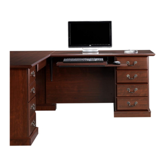
48" Return Kit
Heritage Hill Collection | 109848
Need help? Visit Sauder.com to view video assembly tips or chat with a live rep.
Prefer the phone? Call 1-800-523-3987.
Share your journey!
Go all Wall Street
on everyone.
NOTE: THIS INSTRUCTION
BOOKLET CONTAINS IMPORTANT
SAFETY INFORMATION.
PLEASE READ AND KEEP FOR
FUTURE REFERENCE.
English pg 1-39
Français pg 40-45
Español pg 46-52
Lot # 372723
06/01/15
Purchased: __________________
Be sure to give us a ring before
making any returns. 1-800-523-3987
Advertisement

Related Manuals for Sauder 109848


Summary of Contents for Sauder 109848
- Page 1 Heritage Hill Collection | 109848 NOTE: THIS INSTRUCTION BOOKLET CONTAINS IMPORTANT SAFETY INFORMATION. Need help? Visit Sauder.com to view video assembly tips or chat with a live rep. PLEASE READ AND KEEP FOR FUTURE REFERENCE. Prefer the phone? Call 1-800-523-3987.
- Page 2 Assembly Tools Required Part Identifi cation No. 2 Phillips Screwdriver Tip Shown Actual Size Hardware Identifi cation Assembly Steps 5-39 Hammer Not actual size Français 40-45 Español 46-52 Skip the power trip. Safety 53-54 This time. Warranty Page 2 109848 www.sauder.com/services...
- Page 3 OUTER END (1) RIGHT MOLDING (1) SHORT SKIRT (1) INNER END (1) LEFT MOLDING (1) KEYBOARD SHELF (1) TOP (1) SHORT MOLDING (1) SLIDING SHELF (1) MODESTY PANEL (1) END MOLDING (2) BOTTOM (1) LONG SKIRT (2) www.sauder.com/services 109848 Page 3...
- Page 4 BLACK 1-7/8" FLAT HEAD SCREW - 6 BROWN 1-1/2" FLAT HEAD SCREW - 3 BLACK 7/8" LARGE HEAD SCREW - 4 SILVER 1-1/8" FLAT HEAD SCREW - 12 BLACK 9/16" LARGE HEAD SCREW - 40 BLACK 9/16" WAFER HEAD SCREW - 2 Page 4 109848 www.sauder.com/services...
- Page 5 SHORT MOLDING (H) to the TOP (C). Use twelve SILVER 1-1/8" FLAT HEAD SCREWS (EE). NOTE: Do not overtighten the SCREWS into the TOP. å SILVER 1-1/8" FLAT HEAD SCREW (12 used for the MOLDINGS) Do not overtighten the SCREWS (EE). www.sauder.com/services 109848 Page 5...
- Page 6 Push the release lever in and pull the SLIDE from the RAIL. Open end Unfi nished edge (8 used) Open end BLACK 9/16" LARGE HEAD SCREW (8 used for the SHELF GLIDES) BLACK 7/8" LARGE HEAD SCREW (4 used for the KEYBOARD SLIDES) Page 6 109848 www.sauder.com/services...
- Page 7 Step 3 The diagram shows the 109843 Executive Desk. å If the keyboard shelf and drawers have already been å inserted into the 109843 Executive Desk, remove them at this time. 109843 Executive Desk www.sauder.com/services 109848 Page 7...
- Page 8 Step 4 You have the choice of assembling this unit four ways: å 1. If attaching the 109848 Return Kit to the right side of å the 109843 Executive Desk (with or without the 109872 U-Shape Connector Kit), continue with step 5.
- Page 9 1/2 turn counter-clockwise. Then, pull the pedestal assembly off of the Top as shown. NOTE: Save these screws and set the pedestal assembly å off to the side. 109843 Right Upright R i g s t y 1. Remove these screws. www.sauder.com/services 109848 Page 9...
- Page 10 Molding and the two screws from the Extension Block. NOTE: Save the screws and set the Modesty Panel, Short å Molding, and Extension Block off to the side. 1. Remove these screws. s t y 109843 r i g Extension Block 109843 Short Molding Page 10 109848 www.sauder.com/services...
- Page 11 Step 7 To begin assembly, push a SAUDER TWIST-LOCK® RETURN KIT(S) ON RIGHT å FASTENER (R) into the indicated holes in the ENDS (A and B) and MODESTY PANEL (D). Do not tighten the TWIST-LOCK® FASTENERS in this step. These holes must be here.
- Page 12 Fasten the MODESTY PANEL (D) to the 109843 Top as å shown. Tighten the TWIST-LOCK® FASTENERS in the MODESTY PANEL. ® How to use the SAUDER TWIST-LOCK FASTENER NOTE: If you pushed TWIST-LOCK® FASTENERS into å 1. Insert the dowel end of the FASTENER into the hole of the the wrong holes in the MODESTY PANEL, pull the adjoining part.
- Page 13 FLAT HEAD SCREWS you removed in step 6. Tighten the TWIST-LOCK® FASTENER in the INNER END (B). å fi n i s h r f a BLACK 1-7/8" FLAT HEAD SCREW (2 used in this step, removed in step 6) www.sauder.com/services 109848 Page 13...
- Page 14 Fasten the OUTER END (A) to the 109843 Short Molding. RETURN KIT(S) ON RIGHT å Tighten the TWIST-LOCK® FASTENERS in the OUTER END. r f a i s h fi n This hole must be here. Page 14 109848 www.sauder.com/services...
- Page 15 SCREWS should be even with the surface of the MOLDING. RETURN KIT(S) ON RIGHT SILVER 1-1/8" FLAT HEAD SCREW (3 used in this step, removed in step 6) F i n i s h r f a www.sauder.com/services 109848 Page 15...
- Page 16 å PANEL (D). Use two BLACK 9/16" LARGE HEAD SCREWS (CC). * U.S. Pat. No. 5,499,886 å Slide the END MOLDING (I) onto the notched edge. BLACK 9/16" LARGE HEAD SCREW (2 used in this step) Page 16 109848 www.sauder.com/services...
- Page 17 Fasten the BOTTOM (E) to the OUTER END (A) RETURN KIT(S) ON RIGHT å and INNER END (B). Use four BLACK 1-7/8" FLAT HEAD SCREWS (Y). BLACK 1-7/8" FLAT HEAD SCREW (4 used in this step) This hole must be here. www.sauder.com/services 109848 Page 17...
- Page 18 RETURN KIT(S) ON RIGHT å Use a BLACK 9/16" LARGE HEAD SCREW (CC). NOTE: Be sure the BRACKETS are even with the edges of å the LONG SKIRTS (J). BLACK 9/16" LARGE HEAD SCREW (2 used in this step) Page 18 109848 www.sauder.com/services...
- Page 19 BOTTOM (E). Use two BLACK 9/16" LARGE HEAD SCREWS (CC). Stand your unit upright. å BLACK 9/16" WAFER HEAD SCREW (2 used for the FEET) BLACK 9/16" LARGE HEAD SCREW (2 used for the METAL BRACKETS) www.sauder.com/services 109848 Page 19...
- Page 20 Extension Block. Tighten the Twist-Lock® Fasteners in the Right End and Right Upright. 109843 Right End R i g r i g Surface with more holes 109843 Extension Block SILVER 1-1/8" FLAT HEAD SCREW (2 used in this step, removed in step 6) Page 20 109848 www.sauder.com/services...
- Page 21 I S T - L O ® F A S T E N E R BLACK 1-7/8" FLAT HEAD SCREW (2 used in this step, removed in step 5) www.sauder.com/services 109848 Page 21...
- Page 22 NOTE: There is no pre-drilled hole for this SCREW. Use a little extra force to get it started. å Push the release lever in and pull the SLIDE from the RAIL. RETURN KIT(S) ON RIGHT s t y Open end Open end BLACK 9/16" LARGE HEAD SCREW (7 used in this step) Page 22 109848 www.sauder.com/services...
- Page 23 With someone’s help, carefully position the 109848 Return Kit next to the 109843 Executive Desk. å Fasten two CONNECTOR PLATES (T) to the bottom of the MOLDINGS on the 109848 Return Kit and 109843 Executive Desk. å Use sixteen BLACK 9/16" LARGE HEAD SCREWS (CC).
- Page 24 Then, pull the pedestal assembly off of the Top as shown. NOTE: Save these screws and set the pedestal assembly å off to the side. 109843 Left Upright s t y 1. Remove these screws. Page 24 109848 www.sauder.com/services...
- Page 25 NOTE: Save the screws and set the Modesty Panel, Short å Molding, and Extension Block off to the side. 1. Remove these screws. s t y 109843 R i g Extension r i g Block 109843 Short Molding www.sauder.com/services 109848 Page 25...
- Page 26 Assemble your unit on a carpeted fl oor or on the empty RETURN KIT(S) ON LEFT å carton to avoid scratching your unit or the fl oor. To begin assembly, push a SAUDER TWIST-LOCK® å FASTENER (R) into the indicated holes in the ENDS (A and B) and MODESTY PANEL (D).
- Page 27 FASTENERS back out of the holes and insert them into the proper holes. Pull at the front and back edges, slowly working the FASTENERS out of the holes. How to use the SAUDER TWIST-LOCK ® FASTENER 1. Insert the dowel end of the FASTENER into the hole of the Fasten the 109843 Right Upright to the MODESTY å...
- Page 28 FLAT HEAD SCREWS you removed in step 21. Tighten the TWIST-LOCK® FASTENER in the INNER END (B). å i s h fi n r f a BLACK 1-7/8" FLAT HEAD SCREW (2 used in this step, removed in step 21) Page 28 109848 www.sauder.com/services...
- Page 29 Fasten the OUTER END (A) to the 109843 Short Molding. RETURN KIT(S) ON LEFT å Tighten the TWIST-LOCK® FASTENERS in the OUTER END. This hole must be here. fi n i s h r f a www.sauder.com/services 109848 Page 29...
- Page 30 SCREWS should be even with the surface of the MOLDING. SILVER 1-1/8" FLAT HEAD SCREW (3 used in this step, removed in step 21) i s h F i n r f a Page 30 109848 www.sauder.com/services...
- Page 31 Fasten two CORD MANAGERS (S) to the MODESTY PANEL (D). å Use two BLACK 9/16" LARGE HEAD SCREWS (CC). * U.S. Pat. No. 5,499,886 å Slide the END MOLDING (I) onto the notched edge. BLACK 9/16" LARGE HEAD SCREW (2 used in this step) www.sauder.com/services 109848 Page 31...
- Page 32 Fasten the BOTTOM (E) to the OUTER END (A) RETURN KIT(S) ON LEFT å and INNER END (B). Use four BLACK 1-7/8" FLAT HEAD SCREWS (Y). BLACK 1-7/8" FLAT HEAD SCREW (4 used in this step) This hole must be here. Page 32 109848 www.sauder.com/services...
- Page 33 RETURN KIT(S) ON LEFT å Use a BLACK 9/16" LARGE HEAD SCREW (CC). NOTE: Be sure the BRACKETS are even with the edges of å the LONG SKIRTS (J). BLACK 9/16" LARGE HEAD SCREW (2 used in this step) www.sauder.com/services 109848 Page 33...
- Page 34 BOTTOM (E). Use two BLACK 9/16" LARGE HEAD SCREWS (CC). Stand your unit upright. å BLACK 9/16" WAFER HEAD SCREW (2 used for the FEET) BLACK 9/16" LARGE HEAD SCREW (2 used for the METAL BRACKETS) Page 34 109848 www.sauder.com/services...
- Page 35 Extension Block. Tighten the Twist-Lock® Fasteners in the Left End and Left Upright. 109843 Left End r i g Surface with more holes 109843 Extension Block SILVER 1-1/8" FLAT HEAD SCREW (2 used in this step, removed in step 21) www.sauder.com/services 109848 Page 35...
- Page 36 N E R S T E ® F A - L O I S T i t h f a c S u r BLACK 1-7/8" FLAT HEAD SCREW (2 used in this step, removed in step 20) Page 36 109848 www.sauder.com/services...
- Page 37 NOTE: There is no pre-drilled hole for this SCREW. Use a little extra force to get it started. å Push the release lever in and pull the SLIDE from the RAIL. RETURN KIT(S) ON LEFT s t y Open end Open end BLACK 9/16" LARGE HEAD SCREW (7 used in this step) www.sauder.com/services 109848 Page 37...
- Page 38 With someone’s help, carefully position the 109848 Return Kit next to the 109843 Executive Desk. å Fasten two CONNECTOR PLATES (T) to the bottom of the MOLDINGS on the 109848 Return Kit and 109843 Executive Desk. å Use sixteen BLACK 9/16" LARGE HEAD SCREWS (CC).
- Page 39 Insert the small drawers, large drawers, keyboard shelves, å and sliding shelf into the 109843 Executive Desk and 109848 Return Kit. You may refer to step 19 of the 109843 instruction book. NOTE: You have the option of attaching the keyboard å...
- Page 40 élément et conserver le livret pour future référence. EXTRÉMITÉ EXTERNE ..........1 GLISSIÈRE DE TABLETTE DE CLAVIER ..2 Pour contacter Sauder EXTRÉMITÉ INTERNE ..........1 COULISSEAU DE TABLETTE DE CLAVIER ..2 en ce qui concerne cet DESSUS ................1 COULISSE DE TABLETTE ........2...
- Page 41 : EXTRÉMITÉS (A et B) et le VOILE DE FOND (D). 1. Pour fi xer le Kit de Retour 109848 à la droite du Bureau Ministre 109843 (avec ou sans le Kit de connecteur en U 109872), ÉTAPE 8 procéder à...
- Page 42 à travers l’intérieur du montant gauche et dans le chant du VOILE DE FOND. ÉTAPE 14 Utilisation de la FIXATION TWIST-LOCK® SAUDER Fixer une CONSOLE EN MÉTAL (V) à chaque PLINTHE 1. Insérer l'extrémité fi letée de la FIXATION dans le trou de la LONGUE (J).
- Page 43 Pour commencer l'assemblage, enfoncer une FIXATION TWIST-LOCK® pour la troisième VIS. Il faudra forcer un peu pour serrer cette VIS. SAUDER (R) dans les trous indiqués des EXTRÉMITÉS (A et B) et le VOILE DE FOND (D). IMPORTANT : Le Kit de retour 9848-015 doit être attaché au Bureau ministre 109843 comme il l’est indiqué...
- Page 44 VOILE DE FOND. Fixer le DESSOUS (E) à l'EXTRÉMITÉ EXTERNE (A) et à l'EXTRÉMITÉ Utilisation de la FIXATION TWIST-LOCK® SAUDER INTERNE (B). Utiliser quatre VIS TÊTE PLATE 48 mm NOIRES (Y).
- Page 45 REMARQUE : Il n’y a pas de trou pré-percé pour cette VIS. Utiliser un peu de force pour la démarrer. ÉTAPE 35 Le schéma représente le Kit de retour 109848 sur la droite du Bureau ministre 109843. Insérer les petits tiroirs, les grands tiroirs, les tablettes de clavier et la tablette coulissante dans le Bureau ministre 109843 et le Kit de retour 109848.
- Page 46 RIEL DE TECLADO .............2 et conserver le livret pour future référence. EXTREMO INTERNO ..........1 CORREDERA DE TECLADO .......2 Pour contacter Sauder PANEL SUPERIOR ............1 CORRIMIENTO DE ESTANTE ......2 en ce qui concerne cet (JUEGO DE EXTENSIÓN SE MUESTRA POR SEPARADO) VELO DE FONDO ............1...
- Page 47 Se ofrecen cuatro opciones para el ensamblaje de esta unidad: Para comenzar el ensamblaje, empuje un SUJETADOR 1. Para fi jar el Kit de Mesa Auxiliar 109848 al lado derecho del TWIST-LOCK® SAUDER (R) dentro de los agujeros indicados Escritorio Ejecutivo 109843 (con o sin el Kit de Conexión en U de los EXTREMOS (A y B) y del VELO DE FONDO (D).
- Page 48 5 e insértelos en el paral izquierdo y en el borde del VELO PERDIDA de 48 mm (Y). DE FONDO. Cómo utilizar el SUJETADOR TWIST-LOCK® SAUDER PASO 14 1. Inserte el extremo con cabilla del SUJETADOR en el agujero de Fije un SOPORTE DE METAL (V) al cada FALDÓN LARGO (J).
- Page 49 Fije dos PLACAS DE CONECTOR (T) a la parte inferior de las corta y los dos tornillos del bloque de extensión. MOLDURAS en el kit de mesa auxiliar 109848 y en el escritorio NOTA: Guarde los tornillos y coloque a un lado el velo de fondo, la ejecutivo 109843.
- Page 50 20 e insértelos en el paral derecho y en el borde del VELO DE FONDO. Deslice una MOLDURA DE EXTREMO (I) patentada* sobre los dos Cómo utilizar el SUJETADOR TWIST-LOCK® SAUDER bordes con muesca del EXTREMO EXTERNO (A) y del EXTREMO INTERNO (B). Cuidadosamente deslice ambas MOLDURAS hasta 1.
- Page 51 CABEZA GRANDE de 14 mm (CC) entre este agujero y entre extremo izquierdo y el paral izquierdo. el velo de fondo. NOTA: No hay agujeros ya perforados para este TORNILLO. Use un poco de fuerza para iniciar la perforación. www.sauder.com/services 109848 Page 51...
- Page 52 PASO 34 PASO 35 Cuidadosamente ponga la unidad en posición vertical. El diagrama muestra el kit de mesa auxiliar 109848 en el lado derecho del escritorio ejecutivo 109843. Si también compró el kit conector en forma de U 109872, diríjase a este libro de instrucciones ahora.
- Page 53 à Les téléviseurs peuvent être particulièrement un téléviseur. cet eff et. lourds. De plus, le poids et l’emplacement du tube image ont tendance à rendre les téléviseurs instables et enclins à tomber vers l’ a vant. www.sauder.com/services 109848 Page 53...
- Page 54 Además, el peso y la ubicación del tubo de imagen tienden a causar la inestabilidad de televisores y propensa a volcarse hacia adelante. Page 54 109848 www.sauder.com/services...
- Page 55 à compter de la date d'achat la première fois et qui sont signalés à Sauder dans les limites de couverture de la contre tout défaut de matériaux ou de fabrication des composantes de mobilier Sauder.
- Page 56 Dear Valued Customer: So, how did it go? Thanks so much for choosing Sauder® furniture. I hope the Set a world record for speed? purchase and assembly process was a positive experience Feeling good about yourself? and you feel good about the furniture you just built. If you Nice.
Need help?
Do you have a question about the 109848 and is the answer not in the manual?
Questions and answers