Chapters
Table of Contents

Related Manuals for WIKA air2guide A2G-85


Summary of Contents for WIKA air2guide A2G-85
- Page 1 Operating instructions Betriebsanleitung Ventilation duct sensor for CO and temperature Model A2G-85 Lüftungskanalfühler für CO und Temperatur Typ A2G-85 Model A2G-85...
- Page 2 Operating instructions model A2G-85 Page 3 - 26 Betriebsanleitung Typ A2G-85 Seite 27 - 49 © 03/2011 WIKA Alexander Wiegand SE & Co. KG All rights reserved. / Alle Rechte vorbehalten. WIKA is a registered trademark in various countries. ® WIKA ist eine geschützte Marke in verschiedenen Ländern.
-
Page 3: Table Of Contents
2. Design and function 3. Safety 4. Transport, packaging and storage 5. Commissioning, operation 6. Menu navigation 7. Maintenance, cleaning and recalibration 8. Dismounting, return and disposal 9. Specifications Declarations of conformity can be found online at www.wika.com. WIKA operating instructions model A2G-85... -
Page 4: General Information
The general terms and conditions contained in the sales ■ documentation shall apply. Subject to technical modifications. ■ Further information: ■ - Internet address: www.wika.de / www.wika.com www.air2guide.com - Relevant data sheet: SP 69.07 WIKA operating instructions model A2G-85... -
Page 5: Design And Function
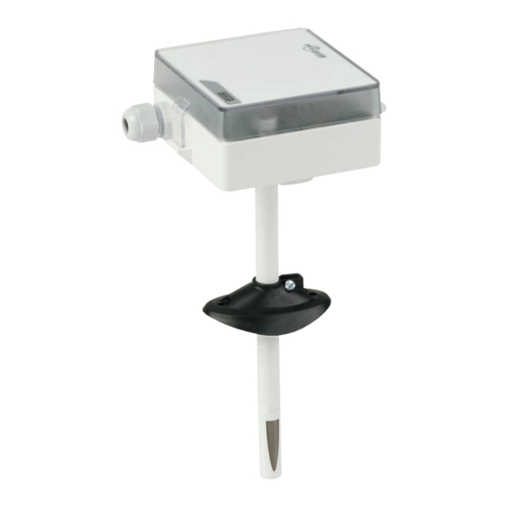
(CO ) in accordance with the NDIR measurement principle, and in addition also temperature. Due to the combination of these two measurands in one single instrument, the material and mounting cost is considerably reduced. WIKA operating instructions model A2G-85... - Page 6 Adjustable 40 … 155 mm Dimensions in mm [in] Ø G 95.5 88.5 2.4 Scope of delivery Digital ventilation duct sensor for CO₂ and temperature ■ Mounting flange ■ Cross-check scope of delivery with delivery note. WIKA operating instructions model A2G-85...
-
Page 7: Safety
The model A2G-85 ventilation duct sensor is used for the detection of carbon dioxide (CO ) and temperature in living, office and production spaces, assembly rooms, rooms for large gatherings, etc. This instrument is not permitted to be used in hazardous areas! WIKA operating instructions model A2G-85... - Page 8 Improper handling or operation of the instrument outside of its technical specifications requires the instrument to be taken out of service immediately and inspected by an authorised WIKA service engineer. The manufacturer shall not be liable for claims of any type based on operation contrary to the intended use.
- Page 9 The personnel trained by the operator are understood to be personnel who, based on their education, knowledge and experience, are capable of carrying out the work described and independently recognising potential hazards. Special operating conditions require further appropriate knowledge, e.g. of aggressive media. WIKA operating instructions model A2G-85...
- Page 10 Supply: DC 24 V / AC 24 V ±10 % < 1 W E-Nr. 66209848 Made in EU Model Measuring range Output signal Supply voltage Serial number Before mounting and commissioning the instrument, ensure you read the operating instructions! WIKA operating instructions model A2G-85...
-
Page 11: Transport, Packaging And Storage
Avoid exposure to the following factors: Direct sunlight or proximity to hot objects ■ Mechanical vibration, mechanical shock (putting it down hard) ■ Soot, vapour, humidity, dust and corrosive gases ■ Hazardous environments, flammable atmospheres ■ WIKA operating instructions model A2G-85... -
Page 12: Commissioning, Operation
Damage to the instrument When working on open electric circuits (PCBs) there is a risk of damaging sensitive electronic components through electrostatic discharge. ▶ The correct use of grounded working surfaces and personal armbands is required. WIKA operating instructions model A2G-85... - Page 13 Select a mounting location (at a duct). ■ Use the mounting flange as a template and mark the screw holes. ■ Mount the flange to the duct with the screws (screws are not included ■ in delivery). Mount the flange WIKA operating instructions model A2G-85...
- Page 14 Air flow direction Air flow direction Air flow direction Strain relief directed downwards Strain relief facing down Air flow direction Air flow direction Air flow direction Air flow direction Air flow direction Air flow direction WIKA operating instructions model A2G-85...
- Page 15 Output DC 0/2 … 5/10 V 24 V Supply voltage U Optional mA output Output 4 … 20 mA Output 4 … 20 mA Modbus output signal ® Modbus ® Modbus ® 24 V Supply voltage U WIKA operating instructions model A2G-85...
-
Page 16: Menu Navigation
Keep the selection button “SELECT” pressed for at least 2 seconds to access the menu. ▶ MENU is displayed 2. Selecting and adjusting the parameters Press the “DOWN” button once ▶ Next menu item is displayed XXXXXXXX XXXX WIKA operating instructions model A2G-85... - Page 17 OUT MAX” menu item is displayed 5. Select lower temperature measuring range 0 … 45 °C or 32 ... 112 °F TE OUT MIN 0.0 °C Press the “DOWN” button once ▶ “TE OUT MIN” menu item is displayed WIKA operating instructions model A2G-85...
- Page 18 Press the “DOWN” button once ▶ “CO OFFSET” menu item is displayed 10. Select temperature offset: ±5 °C or ±9 °F TE OFFSET 0.0 °C Press the “DOWN” button once ▶ “TE OFFSET” menu item is displayed WIKA operating instructions model A2G-85...
- Page 19 5. Select the parity bit: None, even, odd PARITY BIT NONE Press the “DOWN” button once ▶ “PARITY BIT” menu item is displayed 6. Press the “SELECT” button in order to exit the menu. SELECT EXIT MENU WIKA operating instructions model A2G-85...
-
Page 20: Maintenance, Cleaning And Recalibration
Improper cleaning may lead to physical injuries and damage to property and the environment. Residual media in the dismounted instrument can result in a risk to persons, the environment and equipment. ▶ Carry out the cleaning process as described below. WIKA operating instructions model A2G-85... -
Page 21: Dismounting, Return And Disposal
▶ Observe the information in the material safety data sheet for the corresponding medium. ▶ Wash or clean the dismounted instrument, in order to protect persons and the environment from exposure to residual media. WIKA operating instructions model A2G-85... - Page 22 During disassembly, there is a danger from aggressive media and high pressures. ▶ Observe the information in the material safety data sheet for the corresponding medium. ▶ Dismount the instrument when there is no pressure. WIKA operating instructions model A2G-85...
- Page 23 8. Dismounting, return and disposal 8.2 Return Strictly observe the following when shipping the instrument: All instruments delivered to WIKA must be free from any kind of hazardous substances (acids, bases, solutions, etc.) and must therefore be cleaned before being returned.
-
Page 24: Specifications
0 … 50 °C [32 … 122 °F] (at sensor) Ambient -20 … +70 °C [-4 … +158 °F] Relative humidity 0 ... 95 %, non-condensing Ingress protection per IP54 IEC/EN 60529 Weight 150 g Mounting Via adjustable mounting flange WIKA operating instructions model A2G-85... - Page 25 Baud rate 9,600, 19,200, 38,400 - adjustable in the configuration Modbus addresses 1 … 247 addresses selectable in the configuration menu ® For further specifications, see WIKA data sheet SP 69.07 and the order documentation. WIKA operating instructions model A2G-85...
- Page 26 WIKA operating instructions model A2G-85...
- Page 27 1. Allgemeines 2. Aufbau und Funktion 3. Sicherheit 4. Transport, Verpackung und Lagerung 5. Inbetriebnahme, Betrieb 6. Menüführung 7. Wartung, Reinigung und Rekalibrierung 8. Demontage, Rücksendung und Entsorgung 9. Technische Daten Konformitätserklärungen finden Sie online unter www.wika.de. WIKA Betriebsanleitung Typ A2G-85...
-
Page 28: Allgemeines
Das Fachpersonal muss die Betriebsanleitung vor Beginn aller Arbei- ■ ten sorgfältig durchgelesen und verstanden haben. Es gelten die allgemeinen Geschäftsbedingungen in den Verkaufsun- ■ terlagen. Technische Änderungen vorbehalten. ■ Weitere Informationen: ■ - Internet-Adresse: www.wika.de / www.wika.com www.air2guide.com - Zugehöriges Datenblatt: SP 69.07 WIKA Betriebsanleitung Typ A2G-85... -
Page 29: Aufbau Und Funktion
Der A2G-85 ist eine hochwertige Produktlösung für die Luft- und Klima- technik. Dieser Lüftungskanalfühler misst Kohlendioxid (CO ) nach dem NDIR-Messprinzip und zusätzlich die Temperatur. Die Verbindung dieser beiden Messgrößen in nur einem Gerät reduziert den Kostenaufwand für Material und Montage erheblich. WIKA Betriebsanleitung Typ A2G-85... - Page 30 Regelung oder Gebäudeautomation übermittelt. 2.3 Abmessungen in mm Einstellbar 40 … 155 mm Abmessungen in mm [in] Ø G 95,5 88,5 2.4 Lieferumfang Digitaler Lüftungskanalfühler für CO₂ und Temperatur ■ Montageflansch ■ Lieferumfang mit dem Lieferschein abgleichen. WIKA Betriebsanleitung Typ A2G-85...
-
Page 31: Sicherheit
Der Lüftungskanalfühler Typ A2G-85 dient zur Erfassung von Kohlendi- oxid (CO ) und Temperatur in Wohnräumen, Büroräumen, Produktions- räumen, Versammlungsräumen, Räumlichkeiten für große Menschenan- sammlungen etc. Dieses Gerät ist nicht für den Einsatz in explosionsgefährdeten Berei- chen zugelassen! WIKA Betriebsanleitung Typ A2G-85... - Page 32 Die technischen Spezifikationen in dieser Betriebsanleitung sind einzuhalten. Eine unsachgemäße Handhabung oder ein Betreiben des Gerätes außerhalb der technischen Spezifikationen macht die sofortige Stilllegung und Überprüfung durch einen autorisierten WIKA-Servicemit- arbeiter erforderlich. Ansprüche jeglicher Art aufgrund von nicht bestimmungsgemäßer Verwendung sind ausgeschlossen.
- Page 33 Das vom Betreiber geschulte Personal ist aufgrund seiner Bildung, Kenntnisse und Erfahrungen in der Lage, die beschriebenen Arbeiten auszuführen und mögliche Gefahren selbstständig zu erkennen. Spezielle Einsatzbedingungen verlangen weiteres entsprechendes Wissen, z. B. über aggressive Medien. WIKA Betriebsanleitung Typ A2G-85...
- Page 34 Supply: DC 24 V / AC 24 V ±10 % < 1 W E-Nr. 66209848 Made in EU Messbereich Ausgangssignal Hilfsenergie Seriennummer Vor Montage und Inbetriebnahme des Gerätes unbedingt die Betriebsanleitung lesen! WIKA Betriebsanleitung Typ A2G-85...
-
Page 35: Transport, Verpackung Und Lagerung
Zulässige Bedingungen am Lagerort: Lagertemperatur: -20 ... +70 °C Folgende Einflüsse vermeiden: Direktes Sonnenlicht oder Nähe zu heißen Gegenständen ■ Mechanische Vibration, mechanischer Schock (hartes Aufstellen) ■ Ruß, Dampf, Feuchtigkeit, Staub und korrosive Gase ■ Explosionsgefährdete Umgebung, entzündliche Atmosphären ■ WIKA Betriebsanleitung Typ A2G-85... -
Page 36: Inbetriebnahme, Betrieb
VORSICHT! Beschädigung des Gerätes Bei Arbeiten mit offenen Schaltkreisen (Leiterplatten) besteht die Gefahr empfindliche elektronische Bauteile durch elektro- statische Entladung zu beschädigen. ▶ Die ordnungsgemäße Verwendung geerdeter Arbeitsflä- chen und persönlicher Armbänder ist erforderlich. WIKA Betriebsanleitung Typ A2G-85... - Page 37 3. Gerät ist nun bereit für die Konfiguration. 5.1 Mechanische Montage Montageort (an einem Kanal) wählen. ■ Montageflansch als Schablone verwenden und die Schraubenlöcher ■ markieren. Flansch mit Schrauben am Kanal montieren (Schrauben nicht im ■ Lieferumfang enthalten). Flansch montieren WIKA Betriebsanleitung Typ A2G-85...
- Page 38 Richtung des Luftstroms Richtung des Luftstroms Air flow direction Air flow direction Zugentlastung nach unten gerichtet Strain relief facing down Richtung des Luftstroms Richtung des Luftstroms Richtung des Luftstroms Air flow direction Air flow direction Air flow direction WIKA Betriebsanleitung Typ A2G-85...
- Page 39 Ausgang DC 0/2 … 5/10 V Ausgang DC 0/2 … 5/10 V 24 V Hilfsenergie U Optionaler mA-Ausgang Ausgang 4 … 20 mA Ausgang 4 … 20 mA Modbus -Ausgangssignal ® Modbus ® Modbus ® 24 V Hilfsenergie U WIKA Betriebsanleitung Typ A2G-85...
-
Page 40: Menüführung
1. Gerätemenü wählen Die Auswahltaste „SELECT“ für mindestens 2 Sekunden gedrückt halten, um in das Menü zu gelangen. ▶ MENU erscheint 2. Parameter wählen und anpassen XXXXXXXX Taste „DOWN“ einmal drücken XXXX ▶ Nächster Menüpunkt erscheint WIKA Betriebsanleitung Typ A2G-85... - Page 41 Taste „DOWN“ einmal drücken ▶ Menüpunkt „CO OUT MAX“ erscheint 5. Unteren Temperaturmessbereich wählen 0 … 45 °C oder 32 ... 112 °F TE OUT MIN 0,0 °C Taste „DOWN“ einmal drücken ▶ Menüpunkt „TE OUT MIN“ erscheint WIKA Betriebsanleitung Typ A2G-85...
- Page 42 Dies ist in anspruchsvollen Anwendungen 0 CO notwendig, die eine jährliche Kalibrierung erfordern. Taste „DOWN“ einmal drücken ▶ Menüpunkt „CO OFFSET“ erscheint 10. Temperatur-Offset wählen: ±5 °C oder ±9 °F TE OFFSET 0.0 °C Taste „DOWN“ einmal drücken ▶ Menüpunkt „TE OFFSET“ erscheint WIKA Betriebsanleitung Typ A2G-85...
- Page 43 Taste „DOWN“ einmal drücken ▶ Menüpunkt „BAUD RATE“ erscheint 5. Paritäts-Bit wählen: None, Even, Odd PARITY BIT Taste „DOWN“ einmal drücken NONE ▶ Menüpunkt „PARITY BIT“ erscheint 6. Taste „SELECT“ drücken, um das Menü zu verlassen. SELECT EXIT MENU WIKA Betriebsanleitung Typ A2G-85...
-
Page 44: Wartung, Reinigung Und Rekalibrierung
Fachpersonal durchzuführen. 7.2 Reinigung VORSICHT! Körperverletzungen, Sach- und Umweltschäden Eine unsachgemäße Reinigung führt zu Körperverletzungen, Sach- und Umweltschäden. Messstoffreste im ausgebauten Gerät können zur Gefährdung von Personen, Umwelt und Einrichtung führen. ▶ Reinigungsvorgang wie folgt beschrieben durchführen. WIKA Betriebsanleitung Typ A2G-85... -
Page 45: Demontage, Rücksendung Und Entsorgung
Messstoffreste im ausgebauten Gerät können zur Gefähr- dung von Personen, Umwelt und Einrichtung führen. ▶ Angaben im Sicherheitsdatenblatt für den entsprechenden Messstoff beachten. ▶ Ausgebautes Gerät spülen bzw. säubern, um Personen und Umwelt vor Gefährdung durch anhaftende Messstoff- reste zu schützen. WIKA Betriebsanleitung Typ A2G-85... - Page 46 Die Demontage des Gerätes darf nur durch Fachpersonal erfolgen. ▶ Gerät im stromlosen Zustand demontieren. WARNUNG! Körperverletzung Bei der Demontage besteht Gefahr durch aggressive Medien und hohe Drücke. ▶ Angaben im Sicherheitsdatenblatt für den entsprechenden Messstoff beachten. ▶ Gerät im drucklosen Zustand demontieren. WIKA Betriebsanleitung Typ A2G-85...
- Page 47 8. Demontage, Rücksendung und Entsorgung 8.2 Rücksendung Beim Versand des Gerätes unbedingt beachten: Alle an WIKA gelieferten Geräte müssen frei von Gefahrstoffen (Säuren, Laugen, Lösungen, etc.) sein und sind daher vor der Rücksendung zu reinigen. WARNUNG! Körperverletzungen, Sach- und Umweltschäden durch Messstoffreste Messstoffreste im ausgebauten Gerät können zur Gefähr-...
-
Page 48: Technische Daten
0 … 50 °C [32 … 122 °F] (am Sensor) Umgebung -20 … +70 °C [-4 … +158 °F] Relative Feuchte 0 ... 95 %, nicht kondensierend Schutzart nach IEC/EN 60529 IP54 150 g Gewicht Montage Über einstellbaren Montageflansch WIKA Betriebsanleitung Typ A2G-85... - Page 49 - 1 Bit für Parität - 1 Stop-Bit Baudrate 9.600, 19.200, 38.400 - einstellbar in der Konfiguration Modbus -Adressen 1 ... 247 Adressen wählbar im Konfigurationsmenü ® Weitere technische Daten siehe WIKA-Datenblatt SP 69.07 und Bestell- unterlagen. WIKA Betriebsanleitung Typ A2G-85...
- Page 50 WIKA operating instructions model A2G-85...
- Page 51 WIKA operating instructions model A2G-85...
- Page 52 WIKA subsidiaries worldwide can be found online at www.wika.com. WIKA-Niederlassungen weltweit finden Sie online unter www.wika.de. WIKA Alexander Wiegand SE & Co. KG Alexander-Wiegand-Straße 30 63911 Klingenberg • Germany Tel. +49 9372 132-0 +49 9372 132-406 info@wika.de www.wika.de WIKA operating instructions model A2G-85...
Need help?
Do you have a question about the air2guide A2G-85 and is the answer not in the manual?
Questions and answers