Table of Contents
Advertisement
Quick Links
Advertisement
Table of Contents

Related Manuals for Teledyne Lecroy MDA800A


Summary of Contents for Teledyne Lecroy MDA800A
- Page 1 Motor Drive Analyzer Getting Started Guide...
- Page 2 Teledyne LeCroy documentation for internal educational purposes. Teledyne LeCroy is a trademark of Teledyne LeCroy, Inc. Other product or brand names are trademarks or requested trademarks of their respective holders. Information in this publication supersedes all earlier versions. Specifications are subject to change without notice.
-
Page 3: Table Of Contents
Welcome Thank you for buying a Teledyne LeCroy product. We’re certain you’ll be pleased with the detailed features unique to our instruments. This guide is intended to help you set up a Motor Drive Analyzer and learn some basic operating procedures, so you're quickly working with waveforms. -
Page 4: Introduction
INTRODUCTION Introducing Motor Drive Analyzer Key Specifications The Motor Drive Analyzer (MDA) captures waveforms from drive power Detailed specifications are on the product datasheet at teledynelecroy.com. sections, power transistors and embedded control systems, performing three- Bandwidth 350 MHz to 1 GHz phase power analysis of the complete motor drive in one, high-performance instrument. - Page 5 Measuring terminals are not intended to be connected directly to supply mains. Do not operate with suspected failures. Check body and cables regularly. If any part is damaged, cease operation immediately and sequester the instrument from inadvertent use. MDA800A Getting Started Guide...
-
Page 6: Overview
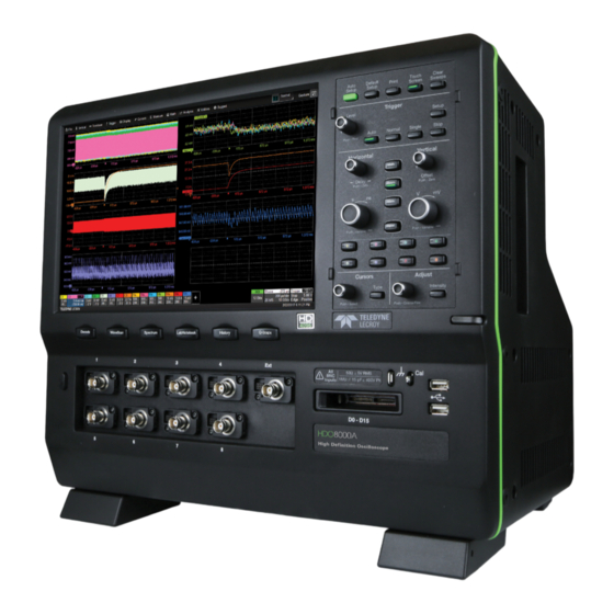
OVERVIEW Front of Motor Drive Analyzer A. Touch Screen Display B. Front Panel C. Shortcut Buttons D. Built-in Stylus Holder E. Power On/Standby Button F. Input Channels 1-4 G. EXT Input H. Mixed Signal Interface I. Ground and Cal Out Terminals J. -
Page 7: Powering On/Off
CAUTION. Do not change the Windows® Power setting to System Standby or System Hibernate. Doing so may cause failure. MDA800A Getting Started Guide... -
Page 8: Back Of Motor Drive Analyzer
OVERVIEW Back of Motor Drive Analyzer A. Built-in Carrying Handle B. Ref In/Out C. Aux Out B C D D. USBTMC Port E. Ethernet Ports (2) F. USB 3.0 Ports (4) G. DisplayPort H. Audio In/Out I. AC Power Inlet J. -
Page 9: Connecting To External Devices/Systems
DP cable. Go to Display > Display Setup > Open Monitor Control Panel to configure display settings using the Windows MDA800A supports USB printers that are compatible with the Windows control panel. Be sure to select the oscilloscope as the primary display. -
Page 10: Side Of Motor Drive Analyzer
OVERVIEW Side of Motor Drive Analyzer The side of the MDA800A houses a removable hard drive. To remove the drive: Loosen the two knobs that secure the cover and remove it. You may use a screwdriver to loosen the knobs. -
Page 11: Front Panel
Most of the front panel controls duplicate functionality available through the touch screen display. They are covered in more detail in the Basics section and in the HDO8000A/MDA800A Oscilloscopes Operator’s Manual. Below are some special front panel controls. A. Auto Setup turns on and configures all channels with a signal attached. -
Page 12: Touch Screen Display
OVERVIEW Touch Screen Display The entire display is active. Use your finger or a stylus to touch, drag-and-drop, swipe, pinch and flick. Many controls that display information also work as “buttons” to access other functions. If you have a mouse installed, you can click anywhere you can touch to activate a control; in fact, you can alternate between clicking and touching, whichever is convenient for you. - Page 13 Dialogs appear at the bottom of the display for entering set up data. The top dialog will be the main entry point for the selected function. Related dialogs appear as a series of tabs behind the main dialog. Apply a custom label to the trace. MDA800A Getting Started Guide...
-
Page 14: Changing The Display
BASICS Changing the Display Q-Scape Multi-Tab Display In addition, the display area can be divided into multiple tabs. Each tab The grid is 8 Vertical divisions representing 4096 Vertical levels and 10 can show a single grid or a multi-grid mode. Horizontal time divisions. - Page 15 The front panel Intensity button sets the Adjust knob to control the trace intensity setting. Trace with Intensity 100% Motor Drive Analyzer with an extended display. Trace with Intensity 40%. MDA800A Getting Started Guide...
-
Page 16: Working With Traces
BASICS Working With Traces Adjusting Setups Trace Descriptor Boxes On setup dialogs, many entries can be made by selecting from the pop-up Channel (C1-C8), Zoom (Z1-Z12), Math (F1-F12), Memory (M1-M12) and menu that appears when you touch a control. Digital (Digital1-Digital4) descriptor boxes appear along the bottom of the grid when a trace is turned on. -
Page 17: Maui With Onetouch
It is now To turn on the Measure table when it is closed, touch the Add New box the active trace. and choose Measurement. MDA800A Getting Started Guide... - Page 18 BASICS Copy Setups Change Source To copy the setup of one trace to another of the same type (e.g., channel to To change the source of a trace, drag-and-drop the descriptor box of the channel, math to math), drag-and-drop the source descriptor box onto the desired source onto the target descriptor box.
- Page 19 To change the trigger source channel, drag-and-drop the desired channel (Cn) the grid. Cursors on the source traces adjust position accordingly. descriptor box onto the Trigger descriptor box. The trigger will revert to the last trigger set on that channel. MDA800A Getting Started Guide...
- Page 20 BASICS Store to Memory Scroll To store a trace to internal memory, drag-and-drop its trace descriptor box To scroll long lists of values or readout tables, swipe the selection dialog or onto the target memory (Mn) descriptor box. table in an up or down direction. Move Trace To move a trace to a different grid, drag-and-drop the trace descriptor box onto the target grid.
- Page 21 Zn descriptor box to open the zoom factor controls and adjust the zoom exactly. To "zoom in" on any trace, unpinch two fingers over the trace horizontally. To "zoom out" on any trace, pinch two fingers over the trace horizontally. MDA800A Getting Started Guide...
-
Page 22: Motor Drive Setup
BASICS Motor Drive Setup The Drive Setup shortcut button immediately below the touch screen opens the Motor Drive Analysis dialog for you to begin configuring your motor drive characteristics. The current settings for AC Input, DC Bus, Drive Output and Mechanical sensors are summarized on this dialog. Use it to navigate to the detailed setup dialogs. -
Page 23: Numerics Table
The table is displayed with the acquisition waveforms. Color overlay marks measurement cycle on Sync signal trace. Measurements for up-to-12 inputs displayed on the Numerics table. Choose the inputs to Choose the motor parameters (MP) display (rows). to display for each input (columns). MDA800A Getting Started Guide... -
Page 24: Waveforms And Statistics
BASICS Waveforms and Statistics Touch a cell of the Numerics table to create a synthesized per-cycle Waveform tracking the value of that motor parameter (MP) over time. This also displays the MP statistics on the Statistics table. As many as 12 per-cycle Waveforms may be created in this way. Use the Waveforms shortcut button to show/hide all per-cycle Waveforms and statistics, or to access the Waveforms + Stats dialog for you to select and modify them. -
Page 25: Zoom And Gate
All measurements gated to width of zooms. Number of measurement cycles matches number shown in zooms (best seen on Sync signal zoom with cycle overlay). MDA800A Getting Started Guide... -
Page 26: Q-Scape Multi-Tab Display
BASICS Q-Scape Multi-Tab Display The Q-Scape shortcut button puts the into tabbed display mode. Press the button again to return to Normal display mode (no tabs). Touch-and-hold Touch the Q-Scape (right-click) on soft button on the tab marker to menu bar to change rename it. -
Page 27: Saving And Sharing Data
LabNotebooks. You can also use the touch screen File > Save Screen Image. File Sharing If the MDA800A is networked, LabNotebooks, reports and other user data files can be emailed directly from the instrument or saved to accessible network devices. -
Page 28: Vertical (Channel)
BASICS Vertical (Channel) Vertical controls adjust traces along the Y axis. Traces represent eight Vertical divisions of the source signal at the selected number of units per division. The zero level is at the center grid line unless you add positive or negative Offset. The front panel Volts knob also controls the Vertical Scale of zoom, math and memory traces. - Page 29 Channel. Touch new Cn descriptor to open the Cn setup dialog. Enter Attenuation for passive and other vendors' probes. Enter Volts/div and Offset. Enter Coupling Apply optional Rescale channel Make any other for cables/probes. Bandwidth Filters. trace, or change Pre-Processing settings. Vertical Unit of grid. MDA800A Getting Started Guide...
-
Page 30: Digital
BASICS Digital On instruments with the Mixed Signal option (HDO8K-MSO), digital selections are added to the Vertical menu, and the front panel Vertical knobs control active Digital line and bus traces. From the Front Panel Digital Descriptor Box # Digital Lines in Group Turn Offset to Digital Sample Rate raise/lower group... - Page 31 Select as you select lines. the state of each the group. and Group Height Custom to enter line: high, low, or in divisions. Optionally, enter unique names. transitioning. a custom line name in the field beneath. MDA800A Getting Started Guide...
-
Page 32: Horizontal (Timebase)
BASICS BASICS Horizontal (Timebase) Horizontal controls adjust traces along the X axis. Analog traces usually represent one acquisition of the source signal for 10 divisions of the selected Time per division. The trigger event is shown at the center of the grid, unless you add positive or negative Delay time. The front panel Time knob also controls the Horizontal Scale of zoom, math and memory traces, allowing you to "zoom in"... - Page 33 Select Sampling Mode. Optionally, enter Delay, Set To Zero Enter fixed Sampling Rate or (negative) time before trigger removes Delay. Maximum Points of memory or (positive) time after trigger to use in acquisition. event to show. MDA800A Getting Started Guide...
-
Page 34: Triggers
Triggers tell the instrument when to perform an acquisition. The acquisition starts as soon as the trigger is armed and all trigger conditions are met, unless postponed by a Holdoff count of time or number of trigger events. Trigger types and modes are described at more length in the HDO8000A/ MDA800A Oscilloscopes Operator’s Manual. From the Front Panel... - Page 35 Trigger setup dialog. Source channel. Choose trigger Type. Set other conditions, Set trigger Level, Icon summarizes the such as Slope and or Find Level based trigger selections. Coupling (vary by on the input signal. trigger type). MDA800A Getting Started Guide...
-
Page 36: Zoom
BASICS Zoom Zoom traces (Zn) display a magnified portion of another trace. Any trace can be zoomed, although Zoom is most useful for channel traces, as it allows you to see the source at the original Timebase at the same time as the Zoom "close up." From the Front Panel When you use the front panel Zoom button, a new Zoom trace is created for every open trace, showing a 10x magnification of the source trace. - Page 37 Draw a Zoom box over a portion of the source trace. Repeat on another section to reposition the Zoom trace. On the source trace setup dialog, touch Action Toolbar Zoom button to create a new zoom of just that source trace. MDA800A Getting Started Guide...
-
Page 38: Cursors
Cursors set measurement points on the Vertical or Horizontal axis of a trace (or both). The five preset cursor types are described in more detail in the HDO8000A/MDA800A Oscilloscopes Operator’s Manual. All show the absolute value where the cursor intersects the waveform and the delta of the two lines. -
Page 39: Measurements & Statistics
Enter Gates (in div) to constrain Turn on Help Markers plot Histogram, Trend or span of measurement, or just drag to show what is being Track of measurement. gate markers from edge of grid. measured on waveform. MDA800A Getting Started Guide... -
Page 40: Math
BASICS Math Math creates a new trace that displays the result of applying a mathematical function (e.g., Sum, Product, FFT) to one or more source traces. Operations can be chained by using one math function as a source for the other. The math trace always opens in a separate grid from the source and can be viewed along side it. -
Page 41: Memories (Reference Waveforms)
Note: Only files saved with the .trc extension can be recalled. Choose Math > Memory Setup. On the Mn tab, select the trace you want stored in Copy From Waveform, then touch Copy Now. Optionally, add Notes or Labels to the stored memory. MDA800A Getting Started Guide... -
Page 42: Decode
BASICS Decode The Action toolbar Decode soft button opens the dialogs for configuring serial decode and trigger options. Decoders apply software algorithms to extract encoded information from physical layer waveforms measured on your instrument. Waveforms are annotated to provide fast, intuitive understanding of the relationship between protocol and signal. -
Page 43: Wavescan
Choose scan Mode (event to find) and Source waveform to search. Take action when an event is found, Select different views of the scan: event table such as sounding a beep. with/without time stamps, overlay, zoom. MDA800A Getting Started Guide... -
Page 44: Spectrum Analyzer
BASICS Spectrum Analyzer Spectrum Analyzer lets you quickly and easily use the Fast Fourier Transform (FFT) for frequency analysis. The controls are the same as you would find on an RF spectrum analyzer. You set the inputs and desired frequency span, and the instrument automatically generates output in units relevant to the frequency domain. -
Page 45: History Mode
"replay" history at varying speeds to capture detailed changes in the waveforms over time. Select row of History table to view that acquisition. Auto Play buttons and slider bar “replay” history View History table to find events of using absolute time interest. or relative time. MDA800A Getting Started Guide... -
Page 46: Maintenance
MDA800A will meet all specifications. CAUTION. Do not attempt to clean internal parts. Warm up the MDA800A for at least 20 minutes prior to use. During the warm-up period, the instrument will automatically initiate calibrations to Language Selection ensure that it is always calibrated. -
Page 47: Firmware Updates
MAINTENANCE Firmware Updates Switching Windows Users Free firmware updates are available periodically from the Teledyne LeCroy Windows 10 oscilloscopes only. website at teledynelecroy.com/support/softwaredownload. Registered Windows 10 oscilloscopes are by default set to operate from the LeCroyUser users will receive email notification when a new update is released. -
Page 48: Service
Service Centers COD or Collect shipments. We recommend air freighting. Insure the item For a complete list of Teledyne LeCroy offices by country, including our you’re returning for at least the replacement cost. Follow these steps for a sales and distribution partners, visit: teledynelecroy.com/support/contact smooth product return. -
Page 49: Support
MERCHANTABILITY, FITNESS, OR ADEQUACY FOR ANY PARTICULAR PURPOSE OR a demonstration of MAUI with OneTouch. USE. TELEDYNE LECROY SHALL NOT BE LIABLE FOR ANY SPECIAL, INCIDENTAL, OR CONSEQUENTIAL DAMAGES, WHETHER IN CONTRACT OR OTHERWISE. THE Teledyne LeCroy publishes a free Technical Library on its website at CUSTOMER IS RESPONSIBLE FOR THE TRANSPORTATION AND INSURANCE teledynelecroy.com/support/techlib. -
Page 50: Certifications
Certifications 2 Emissions which exceed the levels required by this standard may occur when the instrument is Teledyne LeCroy certifies compliance to the following standards as of connected to a test object. the time of publication. Please see the EC Declaration of Conformity 3 This product is intended for use in nonresidential areas only. - Page 51 The has been certified by Underwriters Laboratories (UL) to conform to the following safety standard and bears the UL Listing Mark: All patents pertaining to the MDA800A can be found on our website at: UL 61010-1 Third Edition – Safety standard for electrical measuring and teledynelecroy.com/patents/...
- Page 52 929958-00 Rev A January, 2019 © 2019 Teledyne LeCroy, Inc. All rights reserved.
Need help?
Do you have a question about the MDA800A and is the answer not in the manual?
Questions and answers