Advertisement
Quick Links
Antaira Technologies
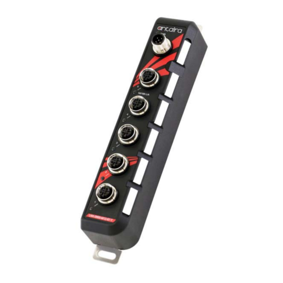
LNX-0500-M12-67 Series
5-Port M12 Industrial IP67 Waterproof Ethernet Switch,
with 5*10/100Tx with M12 Connector
Quick Installation Guide
Version 1.0
(May 2018)
Tel: 1-844-268-2472
Fax: 1-714-671-9944
www.antaira.com
Package Check List
The package contains the following items:
1 – Quick installation guide
1 – LNX-0500-M12-67(-T)
1 – DIN-Rail kit with screws
6 – M12 protective caps
6 – Port labels
Front Panel Layout
Power LED
Power Inputs Port
(M12 5-pin A-Coded Male Connector)
10/100 Ethernet Port 1-5
(M12 4-pin D-Coded Female Connector)
10/100Mbps Link/Activity LED
Product Overview
System Interface/Performance
All Ethernet ports support the auto MDI/MDI-X function
M12 connector with IP67 rated protection
Store-and-forward switching architecture
Power Input & Connection
DC 12 to 48V redundant power
It is recommended to use a UL listed industrial power supply
Operating Temperature
Standard operating temperature model: -10°C to 70°C
Extended operating temperature model: -40°C to 75°C
Case/Installation
IP67 protection
Wall Mount/DIN-Rail design
LED Indicators
LED
Color
On
PWR
Green
Off
On
LAN Port 1~5
Green
Flashing
(LINK/ACT)
Off
19020000000066
Screw Holes for Wall Mounting/Grounding
Power Port Label
Ethernet Port Label
Screw Holes for Wall Mounting/Grounding
Description
Power input 1 or 2 is active
Power input 1 and 2 are inactive
Connected to network, 10/100Mbps
Networking is active
Not connected to network
Quick Installation
Ethernet Ports
M12 Ports (Auto MDI/MDI-X)
All M12 ports (4-Pin D-Coded Female Connector) are
auto-sensing for 10Base-T or 100Base-TX device connections.
Please follow the wiring pin assignment table below for Ethernet
port installation.
M12 4-Pin D-Coded Female Connector
Illustration
Pinouts
10/100Base-T(X) Signal
1
Transmit Data + (TX+)
2
Receive Data + (RX+)
3
Transmit Data - (TX-)
4
Receive Data - (RX-)
Power Input Wiring
• Input voltage: 12-48VDC
• Dual DC power inputs for power redundancy
• Connection format: M12 5-Pin A-Coded male connector
• Suggest using UL listed industrial power supply
• Pin assignment of M12 power connector:
M12 5-Pin A-Coded Male Power Connector
Illustration
Pinouts
Function
1
V1+
2
V2+
3
V2-
4
V1-
5
NOTE: Recommended use the wire gauge between 18~24AWG.
Description
Power Input 1 +
Power Input 2 +
Power Input 2 -
Power Input 1 -
Grounding
Advertisement

Subscribe to Our Youtube Channel
Related Manuals for ANTAIRA LNX-0500-M12-67 Series


Summary of Contents for ANTAIRA LNX-0500-M12-67 Series
- Page 1 6 – Port labels Please follow the wiring pin assignment table below for Ethernet port installation. Front Panel Layout LNX-0500-M12-67 Series M12 4-Pin D-Coded Female Connector Screw Holes for Wall Mounting/Grounding 5-Port M12 Industrial IP67 Waterproof Ethernet Switch, Illustration...
- Page 2 Insert the top of the DIN-Rail on to the track. convenient as possible. expense for shipping the RMA unit(s) to Antaira. Antaira is Lightly pull down the bracket on to the rail.
Need help?
Do you have a question about the LNX-0500-M12-67 Series and is the answer not in the manual?
Questions and answers