Table of Contents
Advertisement
Quick Links
Advertisement
Table of Contents
Troubleshooting

Related Manuals for Fronius WF 15i


Summary of Contents for Fronius WF 15i
- Page 1 Perfect Welding / Perfect Charging / / Solar Energy Operating Instructions WF 15i WF 15i n.S. Wire-feed unit WF 25i WF 30i 42,0426,0116,EN 034-11022020 Fronius prints on elemental chlorine free paper (ECF) sourced from certified sustainable forests (FSC).
- Page 3 Thank you for the trust you have placed in our company and congratulations on buying this high-quality Fronius product. These instructions will help you familiarise yourself with the product. Reading the instructions carefully will enable you to learn about the many different features it has to offer.
-
Page 5: Table Of Contents
Contents Safety rules ..............................General ..............................Proper use ............................Environmental conditions........................Obligations of the operator........................Obligations of personnel ........................Mains connection ..........................Protecting yourself and others ......................Danger from toxic gases and vapours ....................Danger from flying sparks ........................Risks from mains current and welding current..................Meandering welding currents........................ - Page 6 General ..............................Safety..............................Every start-up............................Every 6 months ............................. Disposal ..............................Technical data Technical data............................WF 15i..............................WF 15i n.S............................WF 25i..............................WF 30i..............................HP 70i ..............................HP 95i ..............................HP 120i ..............................HP 70i, HP PC Cable HD 70.........................
-
Page 7: Safety Rules
Safety rules General The device is manufactured using state-of-the-art technology and according to recognised safety standards. If used incorrectly or misused, however, it can cause: injury or death to the operator or a third party, damage to the device and other material assets belonging to the operating company, inefficient operation of the device. -
Page 8: Obligations Of The Operator
Ambient temperature range: during operation: -10 °C to + 40 °C (14 °F to 104 °F) during transport and storage: -20 °C to +55 °C (-4 °F to 131 °F) Relative humidity: up to 50% at 40 °C (104 °F) up to 90% at 20 °C (68 °F) The surrounding air must be free from dust, acids, corrosive gases or substances, etc. -
Page 9: Danger From Toxic Gases And Vapours
Suitable protective clothing must be worn when working with the device. The protective clothing must have the following properties: Flame-resistant Insulating and dry Covers the whole body, is undamaged and in good condition Safety helmet Trousers with no turn-ups Protective clothing refers to a variety of different items. Operators should: Protect eyes and face from UV rays, heat and sparks using a protective visor and reg- ulation filter Wear regulation protective goggles with side protection behind the protective visor... -
Page 10: Danger From Flying Sparks
Flammable vapours (e.g. solvent fumes) should be kept away from the arc's radiation area. Close the shielding gas cylinder valve or main gas supply if no welding is taking place. Danger from fly- Flying sparks may cause fires or explosions. ing sparks Never weld close to flammable materials. -
Page 11: Meandering Welding Currents
Operating the device on a grid without a ground conductor and in a socket without a ground conductor contact will be deemed gross negligence. The manufacturer shall not be held liable for any damage arising from such usage. If necessary, provide an adequate earth connection for the workpiece. Switch off unused devices. -
Page 12: Emf Measures
either radio or television receivers). If this is the case, then the operator is obliged to take appropriate action to rectify the situ- ation. Check and evaluate the immunity to interference of nearby devices according to national and international regulations. Examples of equipment that may be susceptible to interfer- ence from the device include: Safety devices Power, signal and data transfer lines... -
Page 13: Requirement For The Shielding Gas
Never touch the workpiece during or after welding - risk of burns. Slag can jump off cooling workpieces. The specified protective equipment must therefore also be worn when reworking workpieces, and steps must be taken to ensure that other people are also adequately protected. Welding torches and other parts with a high operating temperature must be allowed to cool down before handling. -
Page 14: Danger From Escaping Shielding Gas
Protect shielding gas cylinders containing compressed gas from excessive heat, mechan- ical impact, slag, naked flames, sparks and arcs. Mount the shielding gas cylinders vertically and secure according to instructions to prevent them falling over. Keep the shielding gas cylinders well away from any welding or other electrical circuits. Never hang a welding torch on a shielding gas cylinder. -
Page 15: Safety Measures In Normal Operation
Before transporting the device, allow coolant to drain completely and detach the following components: Wirefeeder Wirespool Shielding gas cylinder After transporting the device, the device must be visually inspected for damage before commissioning. Any damage must be repaired by trained service technicians before com- missioning the device. -
Page 16: Safety Inspection
(e.g. relevant product standards of the EN 60 974 se- ries). Fronius International GmbH hereby declares that the device is compliant with Directive 2014/53/EU. The full text on the EU Declaration of Conformity can be found at the following address: http://www.fronius.com... -
Page 17: General
General... -
Page 19: General
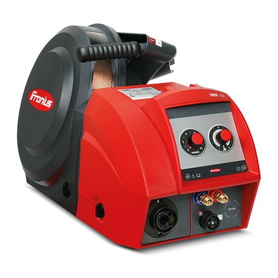
General Device concept The wire-feed units WF 15i, WF 25i, WF 30i are fitted with a cover for wirespools with an outer diameter of up to 300 mm (11.81 in). Also available is the WF 15i n.S. (no Spool) variant without an integrated wirespool hol- der. - Page 20 Attention: Les pièces peuvent être à la tension de soudage 40,0006,3035 WF 15i n.S. Do not use the functions described here until you have thoroughly read and understood the following documents: these operating instructions all the operating instructions for the system components, especially the safety rules Welding is dangerous.
-
Page 21: Controls, Connections And Mechanical Components
Controls, connections and mechani- cal components... -
Page 23: Controls, Connections And Mechanical Components
Function Coolant return connection (red) - is fitted as standard on WF 15i, WF 15i n.S., WF 30i, as an option for WF 25i for connecting the coolant hose from the welding torch hosepack... -
Page 24: Rear Of Wire-Feed Unit
SpeedNet cable Shielding gas connection Function Coolant return connection (red) - is fitted as standard on WF 15i, WF 15i n.S., WF 30i, as an option for WF 25i for connecting the coolant hose from the interconnecting hosepack Coolant flow connection (blue) - is fitted as standard on WF 15i, WF 15i n.S.,... -
Page 25: Wire-Feed Unit Underside
Wire-feed unit un- Function derside Socket for swivel pin (not in the case of WF 15i n.S.) for placing the wire-feed unit on the swivel pin in the swivel pin holder... -
Page 26: Optional Control Panels
Optional control panels Safety WARNING! Danger from incorrect operation. This can result in severe personal injury and damage to property. ► All the functions described may only be used by trained and qualified personnel. ► Fully read and understand this document. ►... -
Page 27: Opt/I Wf Gas Test & Wire Threading
Adjuster functions during TIG welding Setting the welding current Not active OPT/i WF gas test Function & wire threading OPT/i WF gas test & wire threading Operating status LED lights up green when the device is ready for use Gas-test button for setting the required gas flow rate on the pressure regulator Gas will flow out for 30 seconds... - Page 28 Function Wire threading button to thread the wire electrode into the torch hosepack with no accompanying flow of gas or current Wire threading can be performed using one of two methods: Method 1 Threading the wire electrode using the preset feeder inching speed: Press and hold the wire threading button The wire electrode will be threaded 1 mm (0.039 in.) after the wire threading button is pressed...
-
Page 29: Opt/I Wf Standard Control Panel
OPT/i WF Stand- ard control panel (10) (14) (11) (13) (12) - Page 30 Parameter selection button (left) for selecting the parameters listed below. The corresponding indicator lights up when a parameter is select- Material thickness *) in mm or inches Current *) current in A Before the start of welding, the machine automatically displays a standard value based on the programmed parameters.
- Page 31 Parameter selection button (right) for selecting the parameters listed below. The corresponding indicator lights up when a parameter is select- Arc length correction for correcting the arc length - ... shorter arc length 0 ... neutral arc length + ... longer arc length Voltage *) in V Before the start of welding, the machine automatically displays a...
- Page 32 Welding process button for selecting the welding process PULS SYNERGIC - MIG/MAG pulse synergic welding SYNERGIC - MIG/MAG standard synergic welding MANUAL - MIG/MAG standard manual welding JOB - Job Mode STICK - Manual metal arc welding SP (SP = special programs: LSC, PMC, TIG, etc.) - Depending on which package of functions is enabled, various welding pro- cesses can be selected.
-
Page 33: Installation And Commissioning
Installation and commissioning... -
Page 35: Before Installation And Commissioning
60° to the vertical The WF 15i, WF 25i and WF 30i wirefeeders can be set up and operated outdoors in ac- cordance with degree of protection IP23. Avoid direct wetting (e.g. from rain). -
Page 36: Placing Wire-Feed Unit On Swivel Pin Holder
Placing wire-feed unit on swivel pin holder Safety WARNING! Danger from electric current. This can result in severe personal injury and damage to property. ► Turn the power source mains switch to the "O" position. ► Disconnect the power source from the mains. ►... -
Page 37: Connecting Wire-Feed Unit To Power Source
Connecting wire-feed unit to power source Safety WARNING! Danger from electric current. This can result in severe personal injury and damage to property. ► Turn the power source mains switch to the "O" position. ► Disconnect the power source from the mains. ►... -
Page 38: Connecting The Extension Hosepack
Connecting the CAUTION! extension hose- pack Danger from electric current due to inadequate connections. This can result in severe personal injury and damage to property. ► All cables, leads and hosepacks must be properly connected, undamaged, correctly in- sulated and adequately dimensioned. Only on water-cooled hosepack CON = interconnecting hosepack EXT = extension hosepack... -
Page 40: Connecting The Welding Torch
Connecting the welding torch Safety WARNING! Danger from electric current. This can result in severe personal injury and damage to property. ► Turn the power source mains switch to the "O" position. ► Disconnect the power source from the mains. ►... -
Page 41: Inserting/Replacing Feed Rollers
Inserting/replacing feed rollers Safety WARNING! Danger from electric current. This can result in severe personal injury and damage to property. ► Turn the power source mains switch to the "O" position. ► Disconnect the power source from the mains. ► Ensure that the power source remains disconnected from the mains until all work has been completed. - Page 42 CAUTION! Danger from exposed feed rollers. This can result in severe injuries. ► Always fit the protective cover of the 4-roller drive after inserting or replacing a feed roll-...
-
Page 43: Inserting The Wirespool, Inserting The Basket-Type Spool
Inserting the wirespool, inserting the basket-type spool Safety WARNING! Danger from electric current. An electric shock can be fatal. ► Turn the power source mains switch to the "O" position. ► Disconnect the power source from the mains. ► Ensure that the power source remains disconnected from the mains until all work has been completed. -
Page 44: Inserting The Basket-Type Spool
Inserting the bas- CAUTION! ket-type spool Danger from falling basket-type spool. This can result in severe personal injury and damage to property. ► When working with basket-type spools, only use the basket-type spool adapter includ- ed in the scope of supply. CAUTION! Danger from the basket-type spool falling because the locking ring has been placed the wrong way around. -
Page 46: Threading The Wire Electrode
Threading the wire electrode General NOTE! If there is no wire threading button on the wire-feed unit, use the wire threading but- ton of another of the manufacturer's system components to thread the wire, for ex- ample the power source wire threading button. The wire threading button functions in the same way for all system components from the manufacturer. -
Page 47: Threading The Wire Electrode
Threading the CAUTION! wire electrode Danger from welding current and accidental ignition of an arc. This can result in severe personal injury and damage to property. ► Before starting work, disconnect the ground earth connection between the welding sys- tem and the workpiece. CAUTION! Danger from emerging wire electrode. -
Page 48: Setting The Contact Pressure
Setting the con- NOTE! tact pressure Risk from excessive contact pressure. This can result in severe damage to property and poor weld properties. ► Set the contact pressure in such a way that the wire electrode is not deformed but nev- ertheless ensures proper wirefeeding. -
Page 49: Adjust The Brake
Adjust the brake General NOTE! Risk from brake lag. This can result in serious damage to property. ► After releasing the torch trigger / wire threading button the wirespool must stop unreel- ing. ► If it continues unreeling, readjust the brake. Adjusting the CAUTION! brake... -
Page 50: Design Of The Brake
STOP Design of the brake WARNING! Danger from incorrect installation. This can result in severe personal injury and damage to property. ► Do not dismantle the brake. ► Maintenance and servicing of brakes is to be carried out by trained, qualified personnel only. -
Page 51: Start-Up
(not for WF 15i n.S.) Wire electrode threaded in Feed roller contact pressure set Brake set (not for WF 15i n.S.) All covers closed, all side panels in place, all protection devices intact and in their proper place General The wire-feed unit is started by pressing the torch trigger (for manual applications) or by means of a welding start-up signal (for automatic applications). -
Page 53: Troubleshooting, Maintenance And Disposal
Troubleshooting, maintenance and disposal... -
Page 55: Troubleshooting
Troubleshooting Safety WARNING! Danger due to work that has been carried out incorrectly. This can result in severe personal injury and damage to property. ► All the work described below must only be carried out by trained and qualified person- nel. - Page 56 Power source has no function Mains switch is on, but indicators are not lit up Cause: There is a break in the mains lead; the mains plug is not plugged in Remedy: Check the mains lead, ensure that the mains plug is plugged in Cause: Mains socket or mains plug faulty Remedy:...
- Page 57 Irregular wire feed speed Cause: Braking force has been set too high Remedy: Loosen the brake Cause: Hole in the contact tip is too narrow Remedy: Use a suitable contact tip Cause: Faulty inner liner in welding torch Remedy: Check the inner liner for kinks, dirt, etc. and replace if necessary Cause: The feed rollers are not suitable for the wire electrode being used Remedy:...
- Page 58 Poor weld properties Cause: Incorrect welding parameters Remedy: Check the settings Cause: Poor ground earth connection Remedy: Ensure good contact to workpiece Cause: Inadequate or no protective gas shield Remedy: Check the pressure regulator, gas hose, gas solenoid valve, torch gas con- nection, etc.
-
Page 59: Care, Maintenance And Disposal
Care, maintenance and disposal General Under normal operating conditions, the device requires only a minimum of care and main- tenance. However, it is vital to observe some important points to ensure the welding sys- tem remains in a usable condition for many years. Safety WARNING! Danger due to work that has been carried out incorrectly. -
Page 60: Every 6 Months
Every 6 months CAUTION! Danger of damage to electronic components. ► Do not bring the air nozzle too close to electronic components. Open covers, remove device side panels and clean inside of device with dry reduced compressed air. After cleaning, restore device to its original state. Disposal Dispose of in accordance with the applicable national and local regulations. -
Page 61: Technical Data
Technical data... -
Page 63: Technical Data
25.91 x 11.10 x 14.25 in. Weight 13 kg 28.66 Ib. *) D.C. = duty cycle WF 15i n.S. Supply voltage 24 V DC / 60 V DC Nominal current 0,5 A / 1 A Welding current at 10 min / 40 °C (104 °F) 40 % D.C.* 60 % D.C.* 100 % D.C.*... -
Page 64: Wf 25I
40 % D.C.* 60 % D.C.* 100 % D.C.* 500 A 450 A 360 A Maximum shielding gas pressure 7 bar 101.53 psi Coolant Original Fronius Maximum coolant pressure 5 bar 72.53 psi Wire feed speed 1 - 25 m/min 39.37 - 984.25 ipm Wire drive... -
Page 65: Hp 70I
Wirespool weight max. 19 kg max. 41.89 Ib. Degree of protection IP 23 Mark of conformity S / CE Dimensions l x w x h 658 x 282 x 362 mm 25.91 x 11.10 x 14.25 in. Weight 13 kg 28.66 Ib. - Page 68 FRONIUS INTERNATIONAL GMBH Froniusstraße 1, A-4643 Pettenbach, Austria E-Mail: sales@fronius.com www.fronius.com Under www.fronius.com/contact you will find the addresses of all Fronius Sales & Service Partners and locations...
Need help?
Do you have a question about the WF 15i and is the answer not in the manual?
Questions and answers