Cisco UCS C Series Installing Manual
Hide thumbs
Also See for UCS C Series:
- Programmer's manual (138 pages) ,
- Configuration manual (88 pages) ,
- Installing (20 pages)
Table of Contents
Advertisement
Quick Links
Installing the Server
This chapter contains the following topics:
•
•
•
•
•
•
•
•
Preparing for Installation
This section contains the following topics:
Installation Warnings and Guidelines
Note
Warning
Preparing for Installation, on page 1
Installing the Server in a Rack, on page 4
Initial Server Setup, on page 9
NIC Mode and NIC Redundancy Settings, on page 14
Updating the BIOS and Cisco IMC Firmware, on page 15
Accessing the System BIOS, on page 16
Smart Access Serial, on page 16
Smart Access USB, on page 17
Before you install, operate, or service a server, review the
for Cisco UCS C-Series Servers
IMPORTANT SAFETY INSTRUCTIONS
This warning symbol means danger. You are in a situation that could cause bodily injury. Before you
work on any equipment, be aware of the hazards involved with electrical circuitry and be familiar with
standard practices for preventing accidents. Use the statement number provided at the end of each
warning to locate its translation in the translated safety warnings that accompanied this device.
Statement 1071
Regulatory Compliance and Safety Information
for important safety information.
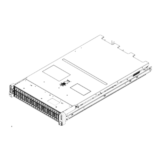
Installing the Server
1
Advertisement
Table of Contents


Need help?
Do you have a question about the UCS C Series and is the answer not in the manual?
Questions and answers