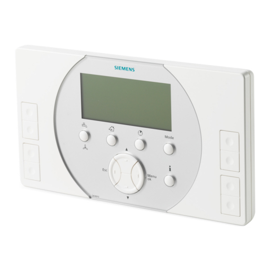
Summary of Contents for Siemens Synco living AP260
- Page 1 Synco living Train the Trainer Mounting Safety Devices August 2007 Page 1/11 Train the Trainer August 2007 Door / Window Contact Smoke Detector...
- Page 2 Mounting Auxiliary Equipment Mounting the Door / Window Contact Door / window contact AP260 The door / window contact is supplied complete with Installation Instructions, battery, magnetic contact, and fixing material. Page 2/11 Train the Trainer August 2007 Door / Window Contact Smoke Detector...
- Page 3 It must be ensured that the SIEMENS logo on the mounting plate (C2) and that on the magnet (C3) are aligned above one another and that the distance...
- Page 4 Mounting Auxiliary Equipment Mounting the Door / Window Contact Mounting location door / window contact AP260 Prior to attaching the RF sensor (E1) to the mounting plate (E2), the transit tab (D4) at the rear of the RF sensor in the battery compartment (D1) must be removed.
- Page 5 Mounting Auxiliary Equipment Mounting the Door / Window Contact Removing door / window contact AP260 For example, to replace the battery of the door / window contact, the RF sensor (H1) must be removed from its mounting plate. To do this, insert a tool (e.g. a small screwdriver (H4)) into the slot between RF sensor (H1) and mounting plate (H2), press the holding nose (H3) down and slide the RF sensor (H1) to the left over the holding...
- Page 6 Mounting Auxiliary Equipment Mounting the Smoke Detector DELTA reflex smoke detector The DELTA reflex smoke detector is supplied complete with Installation Instructions, batteries, and fixing material. Per room, maximum 1 DELTA reflex smoke detector can be fitted. Page 6/11 Train the Trainer August 2007 Door / Window Contact Smoke Detector...
- Page 7 Mounting Auxiliary Equipment Mounting the Smoke Detector DELTA reflex smoke detector To enable the DELTA reflex smoke detector to deliver an alarm via radio link, it requires a smoke detector module M255. DELTA reflex smoke detector Smoke detector module M255 Page 7/11 Train the Trainer August 2007...
- Page 8 Mounting Auxiliary Equipment Mounting the Smoke Detector Mounting location DELTA reflex smoke detector When choosing the mounting location for the smoke detector, the following points must be observed: Every smoke detector can cover an area of max. 60 m Fit the smoke detector as close as possible to the center of the ceiling (minimum distance from wall and corner: 15 cm) In rooms with inclined or pointed ceilings, fit the smoke detector...
- Page 9 Mounting Auxiliary Equipment Mounting the Smoke Detector Unsuited mounting locations for the DELTA reflex smoke detector In rooms, where considerable amounts of water vapor, dust or smoke occur In rooms with open fire places In the vicinity of electrical fields (e.g. fluorescent energy saving lamps and wiring, minimum distance: 50 cm) At locations where ambient temperatures drop below 0 °C or exceed +50 °C...
- Page 10 Mounting Auxiliary Equipment Mounting the Smoke Detector Inserting the smoke detector module Removing the module‘s cover: Insert a screwdriver in the respective opening and push it downward to lift the cover Hold the smoke detector module at the edges, insert it in its respective place and push it downward until the module‘s 2 lateral catches engage Replace the cover to prevent malfunctions...
- Page 11 Mounting Auxiliary Equipment Mounting the Smoke Detector Mounting the DELTA reflex smoke detector Open the 2-sectional device (base B1 and smoke detector B2 ) by holding firmly the base and turning the detector counterclockwise Secure the base (B1) to the ceiling using the enclosed fixing material Insert the 3 enclosed batteries (B2) in the battery compartment (observe correct polarity)


Need help?
Do you have a question about the Synco living AP260 and is the answer not in the manual?
Questions and answers