Advertisement
Quick Links
CERBERUS PYROTRONICS™
MODEL PB-1191
Linear Smoke Detection System
Operation and Installation Manual
Siemens Building Technologies, Inc.
8 Fernwood Road
Florham Park, New Jersey 07932
P/N 315-095424-3
Cerberus Division
Siemens Building Technologies, Ltd.
50 East Pearce Street
Richmond Hill, Ontario L4B 1B7 CN
Advertisement

Related Manuals for Siemens Cerberus Pyrotronics PB-1191


Summary of Contents for Siemens Cerberus Pyrotronics PB-1191
- Page 1 Cerberus Division CERBERUS PYROTRONICS™ MODEL PB-1191 Linear Smoke Detection System Operation and Installation Manual Siemens Building Technologies, Inc. Siemens Building Technologies, Ltd. 8 Fernwood Road 50 East Pearce Street Florham Park, New Jersey 07932 Richmond Hill, Ontario L4B 1B7 CN...
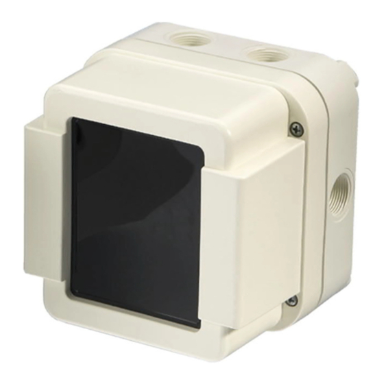
- Page 2 PB-1191 Beam Detector Overview Figure 1 PBA-1191 Characteristics • Microprocessor-controlled signal processing • Suitable for surveillance ranges from 17 to 280 feet • Operates according to the principle of light-attenuation by smoke • Response behavior selectable In 3 sensitivity stages •...
- Page 3 PB-1191 Beam Detector Design The PB-1191 linear smoke detector has the following components: • Base PBB-1191 consisting of: – Terminal support with terminals The base housing features six PG16 tapped cable inlets. • Detector module PBA-1191 consisting of: – Transmitter –...
- Page 4 PB-1191 Beam Detector Operating principle The transmitter (IRLED) emits an invisible infrared (IR) pulse through the transmitter lens. The IR pulse crosses over the measuring section and reaches the reflector located opposite the detector. The reflector deflects the IR pulse back to the point of origin. The receiver lens directs the reflected IR pulse to a silicon photodiode.
-
Page 5: Technical Data
PB-1191 Beam Detector Technical Data Value Parameters Symbol Unit min. typ. max. Conditions Operating voltage (quiescent) Maximum permissible voltage Switch-on current Operating current (quiescent condition) Alarm voltage at I = 1 ... 10mA Alarm current at U = 24V Reset voltage Reset time (U = 2V) Distance between detector and... -
Page 6: Design And Principle Of Operation
PB-1191 Beam Detector Design and Principle of Operation Detector Short Distance Filter Sighting Device (mirror with backsight) Sighting device (foresight) Receiver Lens Locking Screw Knurled Screw For Horizontal Adjustment Knurled Screw For Vertical Adjustment Locking Screw Transmitter Lens Program Switch Detector Heater Terminal Reed Contact (initialization) Connector for... - Page 7 PB-1191 Beam Detector Manual Effective Core Scattered region region region Detector Reflector PBA-1191 PBR-1191 Figure 5 Structure of the infrared beam • The effective region corresponds to the ribbon connecting transmitter, reflector and receiver. • The core region contains sufficient radiation energy to operate the system. •...
- Page 8 PB-1191 Beam Detector Manual Reflector PBR-1191 Detector PBA-1191 22 ft. 5° 5° 22 ft. 280 ft. Figure 8 Vertical adjustment range of the optical system - max. 5° above and below the axis Note: One rotation of the knurled screw moves the beam at 280 ft. approximately 3 ¾ ft. Reflectors Retroreflectors reflect the received light beam in parallel to the latter.
-
Page 9: Compatible Equipment
PB-1191 Beam Detector Manual Light beam Figure 10 PBR-1191 reflector and reflection principle PBR-1192, PBR-1193 reflector This reflector consists of microprismatic elements that are formed by transparent, synthetic resin sealed to a plastic substrate. Compatibility COMPATIBLE EQUIPMENT Zone System Module System - 3 ZB-35 CZM-4... -
Page 10: Fields Of Use
PB-1191 Beam Detector Manual Planning Fundamentals of planning The linear smoke detector PBA-1191 is ideal for certain applications. Use it to supplement or replace point-type smoke detectors. Refer to the Fields of Use table for suitable applications. FIELDS OF USE Very Suitable: Suitable: Large and high halls... - Page 11 PB-1191 Beam Detector Manual Monitoring areas with flat ceilings Min. spacing between two Distance between PBA-1191 parallel beams determined by and reflector 17 - 280 ft. distance PBA-1191 and reflector (See Figure 20) Max. distance from ceiling Max. width of monitored area min 1 ft.
- Page 12 PB-1191 Beam Detector Manual Figure 13 If the ceiling slopes only slightly (N <0.5), the monitoring beam in the gable is unnecessary Both distances are determined by height of the room (See Figure 23.) When the sides of the roof are unequal, the unit must be displaced from the center towards the less steep side.
- Page 13 PB-1191 Beam Detector Manual Monitoring areas with beam constructions Note that the term beams, also covers such structures as air conditioning ducts which are mounted up to 0.5 ft below the ceiling. Layout underneath beam construction If the beam construction is less than 20% of the total height of the room, the units of the linear smoke detector can be mounted below the beams as indicated in Figure 15.
- Page 14 PB-1191 Beam Detector Manual Detection of smoldering fire in high rooms In order to detect smoldering fires with weak thermal current even in high rooms, the second IR beam must be arranged at the assumed height of the spread of smoke of a smoldering fire. Figure 17 Detection of smoldering fires in high rooms with two linear smoke detectors Guideline for distances between PBA-1191 and reflector...
- Page 15 PB-1191 Beam Detector Manual Pane of glass Pane of glass Partial light PBA-1191 PBR-1191 PBA-1191 PBR-1191 scatter Partial light min. 10° scatter CORRECT - THE RECEIVER IS NOT AFFECTED INCORRECT - THE RECEIVER IS AFFECTED Figure 18 With the penetration of panes of glass, check the angle in relation to the optical axis Glass wall PBR-1191 correctly...
- Page 16 PB-1191 Beam Detector Manual Minimum distances between two pairs of detectors The monitoring beam must not be mounted closer than 1 ft. to the ceiling, walls, installations, and stored material. In order to prevent the mutual interference of two or more PBA-1191 detectors where there is an increasing distance between PBA-1191 and reflector, maintain an ever-increasing transverse distance between PBA-1191 and reflector.
- Page 17 PB-1191 Beam Detector Manual NOTE: The steeper the gable roof, the greater the distance must be between the IR beam in the gable and the ridge. Figure 22 Distance from IR beam ⇒ ⇒ ⇒ ⇒ ⇒ sloping ceiling (N > 0,2) Maximum monitoring width The monitoring width can be increased with increasing room height.
- Page 18 PB-1191 Beam Detector Manual Measures against condensation If the PBA-1191 or the reflector is mounted on cool outside walls or in rooms in which there is high humidity and a rapid increase in temperature (e.g. sunshine on a non-insulated roof), use the detector heating unit PBH-1191.
- Page 19 PB-1191 Beam Detector Manual Accessibility The PB-1191 must always be easily accessible in high halls for commissioning and servicing. Suitable equipment for this purpose includes fixed ladders, catwalks, etc. or safe mobile equipment such as stacker trucks, sky-workers etc. Figure 26 Difficult and dangerous work using a ladder Figure 27 Precise and safe work using a permanent plafform...
-
Page 20: Installation
PB-1191 Beam Detector Manual Installation Mounting Surface mounting directly on the wall (minimum clearance to ceiling and other obstacles at least 1 ft) 3/16" 5 3/8" Base PBB-1191 PG16 Detector module Mounting plane PBA-1191 PBB-1191 NOTE: The response indicator should always be at the bottom. - Page 21 PB-1191 Beam Detector Manual Wiring The detector is installed with a twisted 2-wire line from base to base. The PBB-1191 base contains one terminal block with 6 terminals for connecting the detector to the line and for connecting the external response indicator. The terminal block incorporates a slide switch jumper which places the end of line device in the circuit for initial continuity check.
- Page 22 Figure 31 Connection of the dector heater Connection RLI-1 or RLI-2 End of line device To UL Listed Siemens Building Technologies, Inc. Control Panel Response Indicator MB = RED pulse signal (for adjusting the lenses during detector production)
- Page 23 PB-1191 Beam Detector Manual Commissioning Settings • Remove the detector cover. • Set the DIP switches. The detector has 3 sensitivity settings - REDUCED, STANDARD, and INCREASED. Set the response threshold with DIPswitch S1 and S2. The transmitter intensity (strong, weak) is set with DIPswitch S3. The S3 DIPswitch, which governs the transmitter intensity is set to STRONG by default.
- Page 24 PB-1191 Beam Detector Manual Preliminary adjustment Install the alignment device on the detector. The mirror and the front sight must be • installed without play! • Unfasten the locking screw. • Align the detector lens to the reflector. The detector lens can be adjusted with the knurled screws.
- Page 25 PB-1191 Beam Detector Manual Final Adjustment • Set the switch on the adjustment unit to AUTO-RANGE. • Using the knurled screws, fine-adjust the detector lens to display the maximum level in the RANGE display. Note: The knurled screws should be turned slowly in order to avoid large signal jumps.
- Page 26 PB-1191 Beam Detector Manual Initialization To initialize the detector, activate a reed relay located near the internal response indicator with the supplied magnet. A flashing response indicator signals initialization. Reed relay rear of the response indicator Magnet Figure 36 Initialization with the magnet During the initialization, the working range of the electronics (RANGE), the compensation value, all smoothing algorithms and diagnostics, and the staus are set to an initial value.
- Page 27 PB-1191 Beam Detector Manual Troubles / Overhaul Trouble Removing the detector triggers a trouble condition (zone line interruption). Blocking the IR Beam also triggers a trouble condition (in approximately 1 minute). Reflection If a reflective surface comes too close to the coverage area or near the detector, a reflection can occur.
- Page 28 Siemens Building Technologies, Inc. Siemens Building Technologies, Ltd. 8 Fernwood Road 50 East Pearce Street Florham Park, New Jersey 07932 Richmond Hill, Ontario L4B 1B7 CN P/N 315-095424-3...
Need help?
Do you have a question about the Cerberus Pyrotronics PB-1191 and is the answer not in the manual?
Questions and answers