Siemens FDA241 Technical Manual
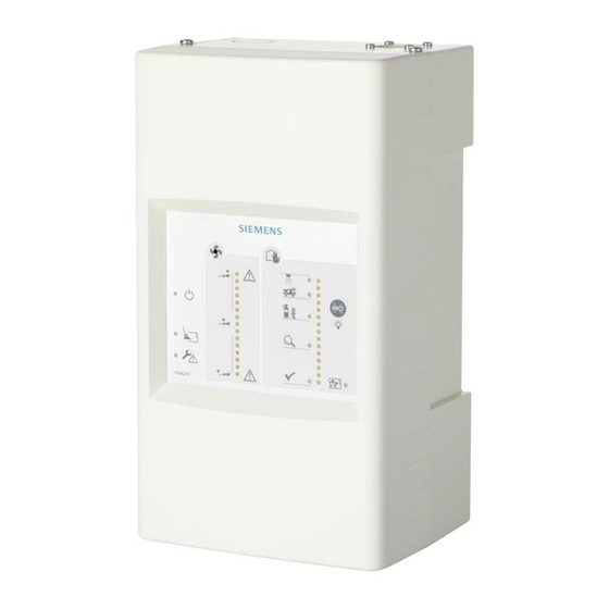
Aspirating smoke detector
Hide thumbs
Also See for FDA241:
- Planning, mounting (56 pages) ,
- Mounting & installation (36 pages) ,
- Manual (6 pages)

Related Manuals for Siemens FDA241


Summary of Contents for Siemens FDA241
- Page 1 FDA241, FDA221 Aspirating Smoke Detector Technical Manual Building Technologies A6V10334410_h_en_-- 2015-09-29 Control Products and Systems...
- Page 2 Legal notice Legal notice Technical specifications and availability subject to change without notice. © Siemens Switzerland Ltd, 2011 Transmittal, reproduction, dissemination and/or editing of this document as well as utilization of its contents and communication thereof to others without express authorization are prohibited.
-
Page 3: Table Of Contents
Table of contents About this document ..................7 Applicable documents ..................9 Download center ....................9 Technical terms ....................10 Revision history ....................11 Safety ......................13 Safety instructions ..................13 Safety regulations for the method of operation ..........14 Standards and directives complied with ............16 Release Notes ....................16 Structure and function .................17 Overview ......................17 3.1.1... - Page 4 'Smoke 4…20 mA' analog output ............. 66 5.3.3 Configurable 'GPI' input ..............68 5.3.4 'Purge' relay output for blowing out (with FDA241 only) ....68 5.3.5 'Dust' relay output for dust value (with FDA241 only) ......69 5.3.6 'Fault' relay output for error messages..........69 5.3.7...
- Page 5 Faults ......................101 8.11.1 Table of faults ................102 8.11.2 Fault analysis ................. 104 Specifications ..................... 105 Technical data for FDA241, FDA221 ............. 105 Dimensions....................108 Environmental compatibility and disposal ............108 Annex ......................109 10.1 Fault indication ..................... 109 Index ........................
- Page 6 Building Technologies A6V10334410_h_en_-- Fire Safety 2015-09-29...
-
Page 7: About This Document
Following the instructions consistently will ensure that the product can be used safely and without any problems. Intended use Aspirating smoke detectors FDA241 and FDA221 may only be used for fire detection and fire control purposes. Target groups The information in this document is intended for the following target groups:... - Page 8 About this document Applicable documents Source language and reference document The source/original language of this document is German (de). The reference version of this document is the international version in English. The international version is not localized. Document identification The document ID is structured as follows: ID code Examples...
-
Page 9: Applicable Documents
Troubleshooting A6V10210424 FS720 Fire detection system - Configuration A6V10229261 List of compatibility (for 'Cerberus™ PRO' product line) A6V10331032 Data sheet Aspirating Smoke Detectors FDA221, FDA241 A6V10332759 Installation, Operation Manual, Configuration 'ASD Configuration Tool FXS2051' A6V10334435 Planning, Installation ASD Pipe system... -
Page 10: Technical Terms
About this document Technical terms Technical terms Term Explanation Acrylonitrile-butadiene-styrene (plastic) Aspirating smoke detector FDnet/C-NET Addressed detector line General Purpose Input, connection for an external switch MC link Maintenance and commissioning link n.c. normally closed (standard state of connection is closed) n.o. -
Page 11: Revision History
'Operation on addressed detector line' ('Selection of settings' > 'Smoke alarm delay time'); 'Testing the airflow' ('Large deviations in the airflow'); 'Power supply'; 'Normalization'; 'Table of faults'; ' 'Dust' relay output for dust value (FDA241 only)'; 'Technical data FDA241, FDA221'... - Page 12 About this document Revision history The table below shows the published language versions and country variants with the corresponding modification index: Modification index en_-- de_-- fr_-- it_-- es_-- – – – – – – – – – – – – –...
-
Page 13: Safety
Safety Safety instructions 2 Safety Safety instructions The safety notices must be observed in order to protect people and property. The safety notices in this document contain the following elements: Symbol for danger Signal word Nature and origin of the danger ... -
Page 14: Safety Regulations For The Method Of Operation
Safety regulations for the method of operation National standards, regulations and legislation Siemens products are developed and produced in compliance with the relevant European and international safety standards. Should additional national or local safety standards or legislation concerning the planning, mounting, installation,... - Page 15 Disregard of the safety regulations Before they are delivered, Siemens products are tested to ensure they function correctly when used properly. Siemens disclaims all liability for damage or injuries caused by the incorrect application of the instructions or the disregard of danger warnings contained in the documentation.
-
Page 16: Standards And Directives Complied With
Safety Standards and directives complied with Standards and directives complied with A list of the standards and directives complied with is available from your Siemens contact. Release Notes Limitations to the configuration or use of devices in a fire detection installation with a particular firmware version are possible. -
Page 17: Structure And Function
Structure and function Overview 3 Structure and function Overview Aspirating smoke detectors are used for early detection of smoke-generating fires in rooms and equipment. They are especially suited to applications in which point detectors are pushed to their limits, cannot be used or can only be used with restrictions. - Page 18 Structure and function Overview The aspirating smoke detector can be operated on an FDnet/C-NET detector line. For this purpose, communication transponder FDCC221S is also required: Aspirating smoke detector on addressed detector line 1 Aspirating smoke detector with 5 Return line (optional) communication transponder FDCC221S 2 External power unit with battery 6 Fire control panel FC20xx/FC72x...
- Page 19 Structure and function Overview Alternatively, various external devices can be connected to the aspirating smoke detector in standalone operation [➙ 37]: Aspirating smoke detector in standalone operation 1 Aspirating smoke detector 6 PC with 'FXS2051 ASD Configuration Tool' software 2 External power unit with battery 7 External control/indicator (optional) 3 Blowing-out unit (optional) 8 External button (optional)
-
Page 20: Details For Ordering
Structure and function Overview Properties Patented technology Can be used with Siemens FDnet/C-NET loop (with optional FDCC221S installed) Extended optical detection thanks to dual wavelengths (blue and infrared) Configuration via USB or FDCC221S (option) 'Out-of-the-box' installation and commissioning ... -
Page 21: Product Version Es
Structure and function Overview 3.1.2 Product version ES The product version ES provides the technical status of a device in terms of software and hardware. The product version is provided as a two-digit number. You will find the details of your device's product version: On the packaging label ... -
Page 22: Setup
Structure and function Setup Setup Components Overview Position Part Function Housing cover Front indicator Operating indicators and fault indicators, connected to the interface card by a cable Opening Cable entry Back box Wall mounting with screws Interface card Connections to external devices and signal equipment. - Page 23 Structure and function Setup Position Part Function Mini USB connection for Interface for configuring the aspirating smoke detector using the 'FXS2051 ASD Configuration Tool' software Air outlet Air outlet in the room or return line connection Cables Connection to the front indicator Contact pins Connection for communication transponder FDCC221S...
-
Page 24: Front Indicator
LED indicators. The buzzer can be switched off and a function test for LEDs and buzzers activated using a button. Front indicator FDA241 Front indicator FDA221 The front indicator can be rotated 180° in the housing cover if necessary. See 'Adapting the front indicator to the installation position [➙... - Page 25 Structure and function Setup Display Designation Function Operating indication The green LED lights up permanently: When the power supply is connected Blowing-out indicator The yellow LED lights up permanently: When the blowing-out process is activated The yellow LED flashes: Once the blowing-out process has been activated until the normal operating status ...
- Page 26 Structure and function Setup Alarming indicator The aspirating smoke detector's current alarm status is indicated by LEDs in the smoke indicator (bar graph indicator). Smoke indicator Number of LEDs lighting up and their meaning 1…5 'Smoke low' Yellow LED 6…9 'Inspect' 10…12 'Prealarm' 13…14 'Fire 1' 15 'Fire 2'...
- Page 27 The 4…20 mA analog output remains on fault. Dust indicator Flashing becomes more frequent as the dust density increases. LED status Meaning Normal operation Slow flashing Low dust value Fast flashing Medium dust value Permanently on High dust value FDA241 only Building Technologies A6V10334410_h_en_-- Fire Safety 2015-09-29...
-
Page 28: Internal Indicator
Structure and function Setup 3.2.2 Internal indicator When the housing cover [➙ 46] is open, the internal indicator is accessible. The internal indicator performs the following functions: Status display for airflow, smoke value, and alarm using 3 LEDs Activate or stop normalization of the airflow using a button ... -
Page 29: Interface Card
Structure and function Setup 3.2.3 Interface card The interface card in the back box is accessible once the housing cover has been removed. You can do the following on the interface card: Establish the cable connection to the front display in the housing cover ... - Page 30 'Purge' relay output for blowing out (with FDA241 only) You will find details on page [➙ 68]. 'Dust' relay output for dust value (with FDA241 only). You will find details on page [➙ 69]. 'Fault' relay output for error messages. You will find details on page [➙ 69].
-
Page 31: External Power Unit And Batteries
Suitable power unit: Company Type For battery type Siemens FP120-Z1 G214130 2x FA2003-A1 (12 V, 7 Ah) 2x FA2004-A1 (12 V, 12 Ah) 2x FA2005-A1 (12 V, 17 Ah) You will find more information on the power supply kit FP120-Z1 in document A6V10393194. -
Page 32: Pipe System
Structure and function Pipe system Pipe system The pipe system must be designed according to the calculation with the 'FXS2055 ASD Asyst Tool' software. The components used for the pipe system must satisfy the requirements according to document A6V10334435. See 'Applicable documents [➙ 9]'. Example pipe system for air aspiration Pipe system 1 Monitored room... -
Page 33: Water Trap In The Pipe System
Structure and function Pipe system 3.3.1 Water trap in the pipe system In the case of highly variable ambient conditions where there is a risk of condensation water forming in the pipe system, a water trap must be used. The water trap collects the condensation water. -
Page 34: Parameter Settings
Structure and function Parameter settings Parameter settings Parameter sets can be used to select the sensitivity with a view to optimizing the aspirating smoke detector for the current application. You will find information about selection and application in the chapter 'Operating modes [➙ 39]'. Function The aspirating smoke detector can be used on a FDnet/C-NET detector line or in standalone operation. -
Page 35: Danger Levels
Structure and function Function 3.5.1.1 Danger levels The aspirating smoke detector can transmit the following danger levels to the fire control panel: Symbol Danger level Designation Inspect Prealarm Fire 1 Fire 2 Configuration in the Sensor 1 Sensor 2 fire detection installation Meaning No danger... -
Page 36: Test Mode
Structure and function Function 3.5.1.3 Test mode For testing purposes the aspirating smoke detectors can be set to test mode. Test mode does the following: The relays are deactivated. The buzzer is operated at a lower sound level. The green operating indicator flashes. -
Page 37: Standalone Operation
2 spacer bolts – 4-pin terminal – ID adhesive label Compatible with: – Aspirating smoke detector FDA241 – Aspirating smoke detector FDA221 Order no.: S24218-A201-A2 See also Installing communication transponder FDCC221S [➙ 62] 3.6.2 Power supply kit A (70 W) FP120-Z1 For converting the mains voltage into system ... -
Page 38: Battery Fa2003-A1 (12 V, 7 Ah, Vds)
– Fire control panels for the 'Sinteso' and 'Cerberus PRO' product lines – External power units for the aspirating smoke detectors FDA241 and FDA221 VdS approval: G103032 Order no.: A5Q00019353 See also Determining the batteries [➙ 42] 3.6.4... -
Page 39: Planning
Planning Compatibility 4 Planning Compatibility Compatible with fire control panels that support the FDnet/C-NET detector line. You will find detailed information in the 'List of compatibility'. The table below shows the compatibility of the aspirating smoke detectors and installed communication transponder FDCC221S with various fire control panels: Detector line Fire control panel FC20xx... -
Page 40: Parameter Sets
Planning Operating modes 4.2.1 Parameter Sets The following information applies to the 'Automatic: switches between blue and blue-red based on ratio' mode. FDA241 Sensitivity [%/m] Comment Inspect Prealarm Fire 1 Fire 2 0.07 0.10 0.15 default 0.03 0.04 0.05 0.03 0.045... -
Page 41: Power Supply
M20 cable grommet: Ø 8…12 mm M25 cable grommet: Ø 9…14 mm Also observe the notices in the 'Technical data for FDA241, FDA221 [➙ 105]' chapter. Capacity calculation Use the following formula to calculate the nominal capacity of the batteries:... -
Page 42: Determining The Batteries
Planning Determining the batteries Determining the batteries If the aspirating smoke detector's power supply via the external power unit fails, power is supplied via batteries. Determining the required battery type The battery capacity depends on the following conditions: Buffer time required ... -
Page 43: Limits To Planning
In rooms where there is an increased risk (rooms with ventilation systems), the size of the monitored area drops to 270…540 m² with the FDA241 (170…340 m² with the FDA221). The maximum monitored area depends on the topology selected and the overall maximum pipe length. -
Page 44: Environmental Influences
Planning Environmental influences Environmental influences If the devices are used in industrial applications, consultation with the project manager is required, since plastics do not withstand certain environmental conditions. The following factors must be taken into consideration: Chemicals Temperature Moisture ... -
Page 45: Mounting / Installation
Mounting / Installation Preparatory work 5 Mounting / Installation Preparatory work 5.1.1 Opening and closing the housing cover when the power supply is switched off When the housing cover is open, the mini USB connection and the internal indicators are accessible. NOTICE Electrostatic discharge Damage to electronic components in the aspirating smoke detector... -
Page 46: Opening And Closing The Housing Cover When The Power Supply Is Switched On
Mounting / Installation Preparatory work Closing the housing cover The size 2 Phillips screwdriver and the two screws are available. The power supply is switched off. 1. Slide the housing cover in the opposite direction to the arrow (step 2) until it reaches the end position at the bottom. - Page 47 Mounting / Installation Preparatory work Opening the housing cover Opening the housing cover The housing is free from dust. 1. Remove the two screws on the top of the aspirating smoke detector using a size 2 Phillips screwdriver (step 1). 2.
-
Page 48: Removing And Installing The Housing Cover When The Power Supply Is Switched Off
Mounting / Installation Preparatory work 5.1.3 Removing and installing the housing cover when the power supply is switched off NOTICE Electrostatic discharge Damage to electronic components in the aspirating smoke detector ● When working on the open aspirating smoke detector, use anti-static floor mats and anti-static work surfaces. - Page 49 Mounting / Installation Preparatory work Removing the housing cover The housing is free from dust. Do not disconnect the connection cable running between the housing cover and the back box. 1. Remove the two screws on the top of the aspirating smoke detector using a size 2 Phillips screwdriver (step 1).
- Page 50 Mounting / Installation Preparatory work Installing the housing cover Markings on the housing cover and back box The size 2 Phillips screwdriver and the two screws are available. 1. Connect the connection cable plug to the interface card! 2. Place the housing cover on the back box so that marking (1) is located between both of the (2) markings.
-
Page 51: Removing And Installing The Housing Cover When The Power Supply Is Switched On
Mounting / Installation Preparatory work 5.1.4 Removing and installing the housing cover when the power supply is switched on NOTICE Electrostatic discharge Damage to electronic components in the aspirating smoke detector ● When working on the open aspirating smoke detector, use anti-static floor mats and anti-static work surfaces. - Page 52 Mounting / Installation Preparatory work Removing the housing cover Removing the housing cover The housing is free from dust. Do not disconnect the connection cable running between the housing cover and the back box. 1. Remove the two screws on the top of the aspirating smoke detector using a size 2 Phillips screwdriver (step 1).
- Page 53 Mounting / Installation Preparatory work The removed housing cover can be hung on the back box. Hanging the removed housing cover on the back box If the connection cable does need to be disconnected, you must switch off the power supply before removing the cable from the interface card. Building Technologies A6V10334410_h_en_-- Fire Safety...
- Page 54 Mounting / Installation Preparatory work Installing the housing cover Markings on the housing cover and back box The size 2 Phillips screwdriver and the two screws are available. 1. Connect the connection cable plug to the interface card! 2. Place the housing cover on the back box so that marking (1) is located between both of the (2) markings.
-
Page 55: Installation Position And Space Requirements
Mounting / Installation Preparatory work 5.1.5 Installation position and space requirements Installation site requirements Only to be installed within a building where the ambient conditions are permissible No direct sunlight Take into account the additional space required by and the need to access the ... - Page 56 Mounting / Installation Preparatory work Four connection types are possible: Standard: From above (A) From below (B) when the aspirating smoke detector is installed rotated by 180° From left (D) or right (E) when the aspirating smoke detector is installed ...
- Page 57 2. Attach the plastic cable entries (usual size M20) to the housing. 3. Insert the cables through the relevant cable entries. See also Adapting the front indicator to the installation position [➙ 58] Technical data for FDA241, FDA221 [➙ 105] Building Technologies A6V10334410_h_en_-- Fire Safety...
-
Page 58: Mounting
Mounting / Installation Mounting Mounting 5.2.1 Adapting the front indicator to the installation position The aspirating smoke detector can be installed rotated by 180° if required. The front indicator must then also be installed rotated by 180°. 180° Adapting the front indicator to the installation position ... -
Page 59: Fastening On A Level Substructure
Mounting / Installation Mounting 5.2.2 Fastening on a level substructure A drilling template is punched in the inner packaging of the aspirating smoke detector packaging. The punched symbol in the center of the packaging indicates the airflow direction (air inlet and air outlet). The mounting holes in the back box are not symmetrical, so use the drilling template. - Page 60 Mounting / Installation Mounting 4. Screw the four screws into the mounting holes. – Do not screw in the screws as far as the stop. A gap of approx. 10 mm must remain between the screw head and the wall. 5.
-
Page 61: Connecting The Pipe System To The Aspirating Smoke Detector
Mounting / Installation Mounting 5.2.3 Connecting the pipe system to the aspirating smoke detector NOTICE Connection between pipe system and aspirating smoke detector Damage to the pipe system and/or the aspirating smoke detector ● Do not glue the pipe system to the aspirating smoke detector! If the pipe system has to be separated from the aspirating smoke detector for maintenance work or repairs, components may be damaged. -
Page 62: Installing Communication Transponder Fdcc221S
Mounting / Installation Mounting 5.2.4 Installing communication transponder FDCC221S Communication transponder FDCC221S may only be installed if the aspirating smoke detector is connected to FDnet/C-NET. Installation is not permitted in the case of standalone operation. Communication transponder FDCC221S has its own ID. The ID of communication transponder FDCC221S is made visible to the detector line and it replaces the ID of the aspirating smoke detector. - Page 63 Mounting / Installation Mounting Mounting The housing cover is open. The aspirating smoke detector's external power supply is switched off and disconnected from the aspirating smoke detector. A communication transponder FDCC221S (accessory) is available. 1. Insert communication transponder FDCC221S into the aspirating smoke detector's interface card with the two spacer bolts as shown in the diagram.
-
Page 64: Installation
Mounting / Installation Installation Installation CAUTION Electrical voltage on lines Risk of injury due to electric shock ● During mounting and installation work, electrical voltage must not be applied to the lines. Note the positive and negative poles. Only connect one wire per terminal. This is the only way to ensure the connection is failure-free for the entire service life of the device. - Page 65 Mounting / Installation Installation Procedure A suitable external power unit is available. The aspirating smoke detector's housing cover is removed. 1. Before connecting the external power unit to the terminal block, check the voltage provided by the power unit. Permissible value: DC 24 V ±4 V 2.
-
Page 66: Smoke 4
Smoke value (device default) Dust value (FDA241 only) Airflow (FDA241 only) Fine dust value (FDA241 only) Example illustrating analog input (IN) Connection for DC 9…25 V power supply Smoke value (device default) 4…20 mA analog output... - Page 67 Mounting / Installation Installation Dust value 4…20 mA analog output No dust 4 mA Low dust value 8 mA Medium dust value 12 mA High dust value 16 mA Very high dust value 20 mA Fine dust value 4…20 mA analog output 0 μg/m³...
-
Page 68: Configurable 'Gpi' Input
Monitoring for short circuit and open line (2 resistors) Input for error monitoring on the external power unit 5.3.4 'Purge' relay output for blowing out (with FDA241 only) Relay output for controlling an external blowing-out unit. Connection: n.o. Properties Suitable for controlling an external blowing-out unit. -
Page 69: Dust' Relay Output For Dust Value (With Fda241 Only)
Mounting / Installation Installation 5.3.5 'Dust' relay output for dust value (with FDA241 only) Relay output for external monitoring of the dust value. Connection: n.o. Properties Suitable for external monitoring of the dust value. Is activated with increased dust concentration. -
Page 70: Prealarm' Relay Output For Pre-Alarm
Mounting / Installation Installation 5.3.8 'PreAlarm' relay output for pre-alarm Relay output for 'pre-alarm' alarm level. Connection: n.o. (default setting) Properties Activation occurs according to the chosen setting. The connection can be changed to 'n.c.' with the 'FXS2051 ASD Configuration ... -
Page 71: Connecting To The Detector Line With The Fdcc221S
2. Check whether the aspirating smoke detector is being supplied with power. The LED lights up. 3. Start the detector line. The aspirating smoke detector is not detected as FDA241 or FDA221 by the fire control panel. If the aspirating smoke detector has not been detected correctly, refer to the fire control panel documentation for the remainder of the process. -
Page 72: Connection To Input/Output Module
Installation 5.3.12 Connection to input/output module Aspirating smoke detectors FDA241 and FDA221 can be connected to a fire control panel via an input/output module. For fire control panels FC20xx and FC72x, the aspirating smoke detector should be connected via the communication transponder FDCC221S, see chapter 'Connecting to the detector line with the FDCC221S [➙... - Page 73 Mounting / Installation Installation Variant 1 (for aspirating smoke detector FDA241 only) Input/output module used: FDCIO222 Monitoring: For open line Example representation of monitoring for open line when using an input/output module FDCIO222 1 Fire control panel 4 Monitoring resistor for GPI input (see chapter 'Configurable 'GPI' input [➙...
- Page 74 Mounting / Installation Installation Interface Function 'GPI' Possible to reset an alarm or the status of the aspirating smoke detector using the fire control panel 'Fault' A general fault is indicated on the fire control panel 'Inspect 1' An early warning is indicated on the fire control panel 'Prealarm' A pre-alarm is indicated on the fire control panel 'Fire 1'...
- Page 75 Mounting / Installation Installation Variant 2 (for aspirating smoke detectors FDA241 or FDA221) Input/output module used: FDCIO222 Monitoring: For open line and short-circuit Example representation of monitoring for open line and short-circuit when using an input/output module FDCIO222 1 Fire control panel 4a, 4b Monitoring resistors for GPI input (see chapter 'Configurable 'GPI' input [➙...
- Page 76 Mounting / Installation Installation Interface Function 'GPI' Possible to reset an alarm or the status of the aspirating smoke detector using the fire control panel 'Fault' A general fault is indicated on the fire control panel 'Prealarm' A pre-alarm is indicated on the fire control panel 'Fire 1' An alarm is indicated on the fire control panel 'Fire 2'...
-
Page 77: Configuration
Configuration 6 Configuration The aspirating smoke detector can be configured in two ways: Via the fire control panel and using the configuration software for the FS20/FS720 (with limited configuration options) Using the 'FXS2051 ASD Configuration Tool' software Values whose parameters were set from the fire control panel cannot be changed with the 'FXS2051 ASD Configuration Tool' software. - Page 78 Configuration Updating the firmware The existing version of the firmware has been checked against the latest version and needs to be updated. The 'FXS2051 ASD Asyst Tool' software is running. The installed version can be displayed on the 'Help' main menu under the 'About' menu. 1.
-
Page 79: Commissioning
2. Check whether the aspirating smoke detector is being supplied with power. The LED lights up. 3. Start the detector line. The aspirating smoke detector is not detected as FDA241 or FDA221 by the fire control panel. If the aspirating smoke detector has not been detected correctly, refer to the fire control panel documentation for the remainder of the process. - Page 80 Commissioning Operation on addressed detector line Selection of settings Field Action Purge activation mode Select the purge interval You can choose from the following: Auto max. 1x Auto max. 2x Auto max. 3x Interval 12 h ...
- Page 81 Commissioning Operation on addressed detector line Field Action Smoke delay time Set the alarm delay for smoke detection. You can choose from the following: Device default 0 sec (EN54-20) 15 sec 60 s 120 sec ...
-
Page 82: Standalone Application
Commissioning Standalone application Standalone application With the standalone option, the aspirating smoke detector is not connected to a fire control panel and is not configured using the configuration software for the FS20/FS720. The aspirating smoke detector is correctly installed. ... -
Page 83: Functional Testing Of The System
Commissioning Functional testing of the system Functional testing of the system 7.3.1 Functional testing of the system with an addressed detector line (FDnet/C-NET) NOTICE Accidental triggering of an alarm Using smoke or aerosols for testing purposes may trigger an alarm unintentionally. -
Page 84: Functional Testing Of The System With The Standalone Option
Commissioning Functional testing of the system 7.3.2 Functional testing of the system with the standalone option NOTICE Accidental triggering of an alarm Using smoke or aerosols for testing purposes may trigger an alarm unintentionally. ● Make sure no alarm is sent to the fire brigade during the test. Testing without alarm transmission/triggering of an alarm ... - Page 85 Commissioning Functional testing of the system Testing with alarm transmission/triggering of an alarm Communication transponder FDCC221S is not installed. The relay outputs are activated. A smoke stick/aerosol spray is available. A connected fire detection installation and the connected alarm devices must be configured as appropriate for the test.
-
Page 86: Testing The Indication Of Faults On The Front Indicator/Internal Indicator
Commissioning Testing the indication of faults on the front indicator/internal indicator Testing the indication of faults on the front indicator/internal indicator To test the indicator, the housing cover can be opened so that the fault indicator flashes. The 'internal indicator' is visible. When you close the housing cover, the fault indicator goes out. -
Page 87: Testing The Airflow
Commissioning Testing the airflow Testing the airflow At the time of commissioning, the airflow through the aspirating smoke detector is measured and this value is saved (normalization [➙ 90]). During operation, the aspirating smoke detector measures the current airflow continually. The current measured value is compared with the saved measured value and any deviations are indicated on the airflow indicator. -
Page 88: Testing The Response Time
Commissioning Testing the response time Large deviations in the airflow outside the set limit parameters If the airflow is outside the set limit parameters (e.g., ±20 %), the fault relay is activated. In the event of other deviations, the LED on the fault indicator lights up and the device reports a fault on all connected interfaces. -
Page 89: Checking And Testing The Power Supply Units
Commissioning Checking and testing the power supply units Checking and testing the power supply units The power supply units must be checked and tested in accordance with the manufacturer's instructions, both on first commissioning and at regular intervals. LED and buzzer test During the test, the following is checked: Function test of the detector indicator ... -
Page 90: Normalization
Commissioning Normalization Normalization During normalization, the aspirating smoke detector is set to the prevailing usage and ambient conditions. This setting cannot be made during detector production. Example: The ambient conditions prevailing in the industrial zone of a large city where there is a lot of air pollution will be very different from those found in a climatic spa town. - Page 91 Commissioning Normalization The airflow is being normalized. The smoke value is being normalized. For firmware version ≥3.10: The LED flashes and the yellow LEDs go out one The central LED flashes. If another LED on the by one. bar graph flashes, this indicates the deviation of the current measured value from the averaged value If normalization was successful, the aspirating smoke detector switches to normal...
- Page 92 The normalization process can only be carried out within a defined range for the airflow values. Please refer to the following table for the limits of the range: Device Lower limit for the airflow Upper limit for the airflow FDA241 15 l/min 57 l/min FDA221 15 l/min...
-
Page 93: Maintenance / Repair
Maintenance / Repair Visual inspection 8 Maintenance / Repair Visual inspection Check the following: Assuming the pipe system is freely accessible, check it is securely attached and free of damage. The aspirating holes of the pipe system are clear. ... -
Page 94: Communication With The Aspirating Smoke Detector
Maintenance / Repair Status queries with service devices 8.3.1 Communication with the aspirating smoke detector Establishing connection between aspirating smoke detector and PC The 'FXS2051 ASD Configuration Tool' software closes automatically when the connection cable is loosened or when the aspirating smoke detector's power supply is interrupted. - Page 95 Maintenance / Repair Status queries with service devices Connecting the aspirating smoke detector to a PC 1 Aspirating smoke detector 4 Mini USB interface 2 Screw connection between housing cover and back box 5 Connection cable 3 Slide housing cover Disconnecting connection between aspirating smoke detector and ...
-
Page 96: Resetting Status Displays And Relay Outputs (Standalone Option)
Maintenance / Repair Resetting status displays and relay outputs (standalone option) 4. Tighten the two screws (2). The aspirating smoke detector (1) is ready for use. The 'FXS2051 ASD Configuration Tool' software closes automatically when the connection cable is loosened or when the aspirating smoke detector's power supply is interrupted. -
Page 97: Performance Check
Maintenance / Repair Performance check Performance check The front indicator and the internal indicator provide information about the aspirating smoke detector's current status. The function of the front indicator can be checked with a test. See 'LED and buzzer test'. [➙ 89] All the relevant settings can be read with the 'FXS2051 ASD Configuration Tool' software. - Page 98 Maintenance / Repair Carrying out water trap maintenance Example of how to arrange a water trap → → Airflow Valve for draining condensation water Aspirating smoke detector with front indicator that is rotated by 180° Outlet opening T-fitting for connecting the water trap at a low horizontal point within the pipe system Distance between manifold and surface of Condensation water...
-
Page 99: Maintenance And Cleaning Intervals
Maintenance / Repair Maintenance and cleaning intervals Maintenance and cleaning intervals The intervals for blowing out the pipe system depend on the level of dirt or may be defined as fixed time intervals. The setting can be made manually or automatically. The setting is made in the 'Purge' menu with the 'FXS2051 ASD Configuration Tool' software. -
Page 100: Event Memory
Maintenance / Repair Event memory Event memory Various changes/events that are not activated or controlled directly by a person are written to the aspirating smoke detector's event memory. The table below shows which events are stored in the event memory: Event Meaning of the saved value Status changed... -
Page 101: Faults
Maintenance / Repair Faults 8.11 Faults Faults are signaled on the front indicator. If there is any uncertainty, we recommend carrying out an LED and buzzer test. During the test, the following is checked: Function test of the detector indicator ... -
Page 102: Table Of Faults
Maintenance / Repair Faults 8.11.1 Table of faults Fault/problem Possible cause Remedy The aspirating smoke detector is not detected by Order not observed when switching Switch the detector line off. the fire control panel on/starting Switch the aspirating smoke detector's external power unit on. - Page 103 Maintenance / Repair Faults Fault/problem Possible cause Remedy Additional deviation in the airflow outside Check the pipe system for damage, e.g., the set limit parameters. cracks, holes, loose connections between the pipes and fittings. Blow out the pipe system. LED lights up Normalize the aspirating smoke detector.
-
Page 104: Fault Analysis
Maintenance / Repair Faults 8.11.2 Fault analysis indicator lights up when faults occur. The fault type is indicated when called. To do this, perform a LED and buzzer test [➙ 89]. When the LED test sequence has finished, the "fault indicator" lights up together with the relevant LED for approximately 3 seconds. -
Page 105: Specifications
20.0…30.0 V. The power supply is switched off to prevent total discharge of the batteries. The aspirating smoke detectors FDA241 and FDA221 issue a warning when a voltage of 21 V is reached before switching off the power supply: The FAULT relay is activated. - Page 106 Specifications Technical data for FDA241, FDA221 Interface for connecting to a PC Mini USB Connection to detector line with FDCC221S FDnet/C-NET (accessory) Connection factor with FDCC221S (accessory) Line separator Line voltage: Nominal DC 32 V (= V Minimum DC 12 V (= V ...
- Page 107 Specifications Technical data for FDA241, FDA221 Pipe system Pipe outer diameter 25 mm Inner diameter of pipe 21 mm Maximum piping lengths for FDA241: Single line FDA241: 60 m Branched lines FDA241: 2 x 60 m Maximum piping lengths for FDA221:...
-
Page 108: Dimensions
Specifications Dimensions Dimensions Dimensions of the aspirating smoke detectors FDA241, FDA221 Environmental compatibility and disposal This equipment is manufactured using materials and procedures which comply with current environmental protection standards as best as possible. More specifically, the following measures have been... -
Page 109: Annex
Annex Fault indication 10 Annex 10.1 Fault indication To make it easier to interpret the fault indicator, you can print this page and keep the graphic and description next to the LEDs that light up. To print this page, set your device to A4 paper without any scaling. -
Page 110: Index
Index Index Detector exchanger and tester Airflow deviation Test device, 36 Operation on detector line, 88 Detector exchanger and tester FDUD292 Standalone mode, 88 MC link, 35 Application area Deviation of airflow Ambient conditions, 44 Operation on detector line, 88 Approvals, 105 Standalone mode, 88 ASD Asyst Tool, 17... - Page 111 Index Housing cover Normal operation, 82, 89, 91, 101 Closing when the power supply is switched off, Normalization, 90 Limits, 92 Closing when the power supply is switched on, Short period, 91 Installing, 50 Installing when the power supply is switched on, Operation on addressed detector line FDnet, 18 Opening, 86...
- Page 112 Index Test device Detector exchanger and tester, 36 Intelligent detector tester, 36 Type plate Product version, 21 USB cable, 94 Building Technologies A6V10334410_h_en_-- Fire Safety 2015-09-29...
- Page 113 Index Building Technologies A6V10334410_h_en_-- Fire Safety 2015-09-29...
- Page 114 Issued by © Siemens Switzerland Ltd, 2011 Siemens Switzerland Ltd Technical specifications and availability subject to change without notice. Building Technologies Division International Headquarters Gubelstrasse 22 CH-6301 Zug Tel. +41 41-724 24 24 www.siemens.com/buildingtechnologies Document ID A6V10334410_h_en_-- Manual FD20/FD720 Edition...
Need help?
Do you have a question about the FDA241 and is the answer not in the manual?
Questions and answers