Subscribe to Our Youtube Channel
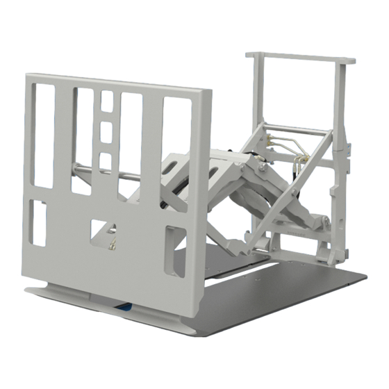
Summary of Contents for cascade corporation QFM Push/Pull E Series
- Page 1 NSTALLATION INSTRUCTIONS and PERIODIC MAINTENANCE E-Series Quick Fork Mount (QFM ) Push/Pull ™ Manual Number 684948-R7 cascade corporation Cascade is a Registered Trademark of Cascade Corporation...
- Page 2 ONTENTS Recommended Hydraulic Supply This Manual provides instructions for installing the Cascade Quick Fork Mount (QFM ) Push/Pull. Follow the ™ suggested installation procedures for best results. If you have any questions or need more information, contact your Truck Requirements nearest Cascade Service Department (see back cover).
- Page 3 RUCK REQUIREMENTS WARNING: Rated capacity of the truck/ attachment combination is a responsibility of the original truck manufacturer and may be less than that shown on the attachment nameplate. Consult the truck nameplate. Truck Relief Setting 2000 psi (140 bar) Recommended 2300 psi (160 bar) Maximum Truck Flow Volume ➀...
- Page 4 NSTALLATION Follow the steps shown to install the Push/Pull and Load Remove banding, attach Push on the truck. Read all WARNINGS and CAUTIONS overhead hoist carefully. If you don't understand a procedure, ask your supervisor, or call the nearest Cascade Service Department for assistance.
- Page 5 NSTALLATION Engage lower hooks Open safety lockpin and turn hooks up. Release safety lockpin to secure hooks up. Adjust clearance and tighten hook capscrews. PP0885.eps 1/8 in. (3.2 mm) Tighten capscrews: 60 ft.-lbs. (80 Nm) Adjust and lock upper hook setscrews Setscrew Adjust clearance for upper hook setscrews.
- Page 6 NSTALLATION Prepare hoses Determine hose lengths required for hydraulic CAUTION: Allow 4-6 in. (10-15 cm) extra hose supply configuration of truck. length for vertical motion for Sheet-Sav ™ Independent Gripper functions. Do not secure Cut hoses to length, install end fittings or hoses until unit is tested (see Step 12).
- Page 7 NSTALLATION Install solenoid control knob – Snap Ring PRESS (Solenoid-equipped units) BUTTON TO CLOSE GRIPPER PRESS PRESS PUSH BUTTON TO SIDESHIFT BUTTON TO PULL PUSH-PULL SAVE SHEET Button toward driver Adapter PRESS PUSH BUTTON TO PULL SAVE SHEET Truck control valve handle PP0321.eps PP1008.eps...
- Page 8 NSTALLATION SCHEMATIC (Single-button control knob) Single-Button Control Knob IMPORTANT: Diode banded end must Control Knob connect to positive Pushbutton White (+) side of circuit. (normally open) 7.5-Amp 7.5-Amp Fuse White Black Fuse Black User-Supplied Wiring IMPORTANT: Recommended wire size 18-AWG minimum with 1/4-in.
- Page 9 NSTALLATION Cycle Attachment functions • WARNING: Make sure all personnel are With no load, cycle all attachment functions clear of the attachment during testing. several times. • Check for operation in accordance with ITA (ISO) standards. • Push/pull a maximum load, sheet save, control gripper bar.
- Page 10 NSTALLATION Adjust platens (if required) Spacers Tighten capscrews to: PP2100.eps 40 ft.-lbs. (55 Nm) WARNING: Forks thicker than 1.50 in. (38 mm) require spacers under the platens to allow the upper mounting hooks to fully engage the upper carriage bar. Spacer kit applications listed below. Platens Fork Spacer Kit...
- Page 11 NSTALLATION Adjust faceplate gripper bar (if required) NOTE: The gripper bar is controlled by sequence valves which are Factory-adjusted to operate as follows: Faceplate Extend – Gripper bar fully raised/up when faceplate reaches full extension. Faceplate Retract – Gripper bar fully lowered/down before faceplate retracts.
- Page 12 ERIODIC MAINTENANCE WARNING: After completing maintenance Faceplate procedures, always test the attachment Push/Pull Frame through five complete cycles. First test the Cylinders attachment empty, then test with a load to make sure the attachment operates correctly before returning it to the job. 100-Hour Maintenance Gripper Every time the lift truck is serviced or every 100 hours...
-
Page 13: 2000-Hour Maintenance
ERIODIC MAINTENANCE 2000-Hour Maintenance After 2000 hours of truck operation, in addition to the 100, 500 and 1000-hour maintenance, forks in use shall be inspected at intervals of not more than 12 months (for single shift operations) or whenever any defect or permanent deformation is detected. - Page 14 Pte. Ltd. Rocklea, QLD 4107 East Tamaki, Auckland 18 Tuas South Street 5 Australia New Zealand Singapore 637796 Tel: 1-800-227-223 Tel: +64-9-273-9136 Tel: +65-6795-7555 Fax: +61 7 3373-7333 Fax: +64-9-273-9137 Fax: +65-6863-1368 Cascade Corporation 2013 06-2013 Part Number 684948-R7...


Need help?
Do you have a question about the QFM Push/Pull E Series and is the answer not in the manual?
Questions and answers