Table of Contents
Advertisement
Quick Links
Advertisement
Table of Contents

Subscribe to Our Youtube Channel
Related Manuals for Spectra PowerBox 3000A Series


Summary of Contents for Spectra PowerBox 3000A Series
- Page 1 Spectra PowerBox 3000A Series USER MANUAL Version 2.40 – October 2021 ...
-
Page 2: Table Of Contents
3.1 Removing the Top Cover ……...……………………………….….…………………..37 3.2 Installing CPU ………………………………………………………………….……………40 3.3 Installing SO-DIMM Memory…………………………………..…………….……………43 3.4 Installing a Mini-PCIe/mSATA Card on Top Side…………………………………..46 3.5 Installing a Mini-PCIe/mSATA Card on Bottom Side……………..…………………...…48 3.6 Installing Antennas…….…….…………..……….…………………………………………..49 Spectra GmbH & Co. KG User Manual sales@spectra.de Spectra PowerBox 3000A... - Page 3 4.4.1 System Agent (SA) Configuration ……………..……………………………………..97 4.4.2 PCH-IO Configuration ………………….……………………………………………..98 4.5 Security Setup …...……….………………….…..…. …………..……………………..100 4.5.1 Administrator Password …….…...………………………………………………….101 4.5.2 User Password …….…………………………………………………..…………….101 4.6 Boot Setup …...……….….……………………………...…..….…..………..…………..101 4.6.1 Setup Prompt Timeout………………………….…………………………………… 101 Spectra GmbH & Co. KG User Manual sales@spectra.de Spectra PowerBox 3000A...
- Page 4 Chapter 5 Product Application (For DIO Only) 5.1 Digital I/O (DIO) application ………..………………………………………………………105 5.1.1 Digital I/O Programming Guide ……………………………………………………105 5.2 Digital I/O (DIO) Hardware Specification …………………………………………………110 5.2.1 PB-3000A-DIO-(i)COM Connector Definition..……...………......111 Spectra GmbH & Co. KG User Manual sales@spectra.de Spectra PowerBox 3000A...
-
Page 5: Revision
2021/08/10 Copyright Notice © 2021 by Spectra GmbH & Co. KG. All rights are reserved. No parts of this manual may be copied, modified, or reproduced in any form or by any means for commercial use without the prior written permission of Spectra GmbH & Co. KG. All information and specification provided in this manual are for reference only and remain subject to change without prior notice. -
Page 6: Declaration Of Conformity
Product Warranty Statement Warranty Spectra products are warranted by Spectra GmbH & Co. KG to be free from defect in materials and workmanship starting from the date of purchase by the original purchaser. The actual warranty period of Spectra products vary with product categories. During the warranty period, we shall, at our option, either repair or replace any product that proves to be defective under normal operation. - Page 7 (such as a fuse, battery, etc.), are not warranted. Before sending your product in, you will need to fill in a Spectra RMA Request Form and obtain a RMA number from us. Please go to www.spectra.de/RMA...
-
Page 8: Technical Support And Assistance
Technical Support and Assistance 1. Visit the Spectra website at www.spectra.de where you can find the latest information about the product. 2. Contact our technical support team or sales representative for technical support if you need additional assistance. Please have following information ready before you call: ... - Page 9 14. CAUTION: Danger of explosion if battery is incorrectly replaced. Replace only with the same or equivalent type recommended by the manufacturer. 15. Equipment intended only for use in a RESTRICTED ACCESS AREA. Spectra GmbH & Co. KG User Manual sales@spectra.de...
-
Page 10: Package Contents
High Performance, Expandable and Modular Rugged Embedded Computer with 1x PCI/PCIe Expansion Slot 7/6th Generation Intel Core Series Processors, Spectra PowerBox High Performance, Expandable and Modular Rugged Embedded 32A* Computer with 2x PCI/PCIe Expansion Slots Spectra GmbH & Co. KG User Manual sales@spectra.de Spectra PowerBox 3000A... -
Page 11: Chapter 1 Product Introductions
Chapter 1 Product Introductions Spectra GmbH & Co. KG User Manual sales@spectra.de Spectra PowerBox 3000A... -
Page 12: Overview
(-40°C to 70°C), wide range DC power input (from 9V to 48V), high tolerance of shock and vibration, high-standard industrial protections and the integrated SuperCap for battery-free operation. The Spectra PowerBox 3000A Series is suitable to deploy in a harsh environment and for critical applications, and it is totally maintenance-free. -
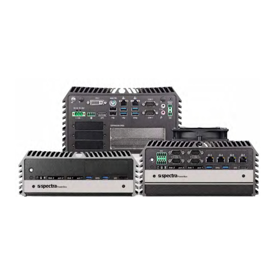
Page 13: Product Pictures
Supports 3x Full-size Mini-PCIe Slot for Wireless & I/O Expansion Wide Operating Temperature (-40°C to 70°C) EN50155 / EN50121-3-2 Certified for Railway Application E-Mark (E13, No.10R-0514229) Certified Safety: LVD EN62368-1 Spectra GmbH & Co. KG User Manual sales@spectra.de Spectra PowerBox 3000A... -
Page 14: Hardware Specification
BIOS • Dimension (WxDxH) / Weight: • AMI 16Mbit SPI BIOS Spectra PowerBox 30Ax : 227 x 261 x 88 mm, 4.70 kg Memory Spectra PowerBox 31Ax : 227 x 261 x 108 mm, 5.22 kg • 2x DDR4 260-pin SO-DIMM socket, support up to 64 GB Spectra PowerBox 32Ax : 227 x 261 x 128 mm, 5.70 kg... -
Page 15: System I/O
Digital I/O LED Removable HDD Bay Indicates the working status of digital input/ Used to inserts a SIM card, CMOS battery, and output 2.5” HDD Spectra PowerBox 30A* Spectra GmbH & Co. KG User Manual sales@spectra.de Spectra PowerBox 3000A... - Page 16 Spectra PowerBox 31A* Spectra PowerBox 32A* Spectra GmbH & Co. KG User Manual sales@spectra.de Spectra PowerBox 3000A...
-
Page 17: Rear
A terminal block used to connect to remote USB 3.0 Port power on/off switch Used to connect USB 3.0/2.0/1.1 device Universal I/O Bracket Used to customized I/O output Spectra PowerBox 30A* Spectra GmbH & Co. KG User Manual sales@spectra.de Spectra PowerBox 3000A... - Page 18 Spectra PowerBox 31A* Spectra PowerBox 32A* Spectra GmbH & Co. KG User Manual sales@spectra.de Spectra PowerBox 3000A...
-
Page 19: Mechanical Dimension
Spectra PowerBox 30A* ... - Page 20 Spectra PowerBox 32A* ...
- Page 21 Chapter 2 Switches & Connectors Spectra GmbH & Co. KG User Manual sales@spectra.de Spectra PowerBox 3000A...
-
Page 22: Location Of Switches And Connectors
2.1 Location of Switches and Connectors 2.1.1 Top View Spectra GmbH & Co. KG User Manual sales@spectra.de Spectra PowerBox 3000A... -
Page 23: Bottom View
2.1.2 Bottom View Spectra GmbH & Co. KG User Manual sales@spectra.de Spectra PowerBox 3000A... -
Page 24: Switches And Connectors Definition
Mini PCI-Express Socket + mSATA + 3G Module CN4,5 Mini PCI-Express / mSATA Socket USB11_12_1 Internal USB 2.0 Ports PCIE1 PCI-Express x16 Socket PCIE2 PCI-Express x1 Socket SODIMM1,2 DDR4 SODIMM Socket Spectra GmbH & Co. KG User Manual sales@spectra.de Spectra PowerBox 3000A... -
Page 25: Definition Of Switches
Function Disable SATA DOM Enable (Default) COM1/2 Voltage Function Setting: Pin Define SW1 Switch Switch Function mode 0V(RI) ON/ON (Default) COM1 ON/OFF OFF/OFF 0V(RI) ON/ON (Default) COM2 ON/OFF OFF/OFF Spectra GmbH & Co. KG User Manual sales@spectra.de Spectra PowerBox 3000A... -
Page 26: Definition Of Connectors
12 SIM_CLK SMB_CLK 48 +1.5V 13 REFCLK+ PETN/SATATN 49 NA 14 SIM_Reset SMB_DATA 50 GND 15 GND PETP/SATATP 51 NA 16 SIM_VPP 52 +3.3V 17 NA 18 GND USB_D- Spectra GmbH & Co. KG User Manual sales@spectra.de Spectra PowerBox 3000A... - Page 27 12 NA SMB_CLK 48 +1.5V 13 REFCLK+ PETN/SATATN 49 NA 14 NA SMB_DATA 50 GND 15 GND PETP/SATATP 51 NA 16 NA 52 +3.3V 17 NA 18 GND USB_D- Spectra GmbH & Co. KG User Manual sales@spectra.de Spectra PowerBox 3000A...
- Page 28 65°C < System Temp ≤ 70°C Blue TEMP LED 70°C < System Temp ≤ 75°C 75°C < System Temp Blinking Red The TEMP LED is only available when IGN module is installed. Spectra GmbH & Co. KG User Manual sales@spectra.de Spectra PowerBox 3000A...
- Page 29 +12V SENSE Control CN6: Remote Power on/off, Remote Reset Switch Connector Definition PWR_SW RESET_SW Do not apply power to this connector! This port is used to connect a SWITCH! Spectra GmbH & Co. KG User Manual sales@spectra.de Spectra PowerBox 3000A...
- Page 30 COM1_2_1: RS232 / RS422 / RS485 Connector Connector Type: 9-pin D-Sub RS422 / 485 RS485 RS232 Full Duplex Half Duplex Definition Definition Definition DATA - DATA + Spectra GmbH & Co. KG User Manual sales@spectra.de Spectra PowerBox 3000A...
- Page 31 COM56_SEL1: COM5 / COM6 with Power Select Connector Type: 2X5 10-pin Header, 2.54mm pitch COM5 COM6 Definition Definition 1-3 On 2-4 On 3-5 On +12V 4-6 On +12V 7-9 On 8-10 On (Default) (Default) Spectra GmbH & Co. KG User Manual sales@spectra.de Spectra PowerBox 3000A...
- Page 32 Full Duplex Half Duplex Definition Definition Definition DATA - DATA + DIO1: Digital Input / Output Connector Connector Type: Terminal Block 2X5 10-pin, 3.5mm pitch Definition Definition DC INPUT Spectra GmbH & Co. KG User Manual sales@spectra.de Spectra PowerBox 3000A...
- Page 33 Connector Type: 9-pin D-Sub RS422 / 485 RS485 RS232 Full Duplex Half Duplex Definition Definition Definition DATA - DATA + COM3/4/5/6 are isolated COM, each pin5 (GND) is independent. Spectra GmbH & Co. KG User Manual sales@spectra.de Spectra PowerBox 3000A...
- Page 34 Connector Type: M12 A coded 8pin connector Definition Definition 2_LAN1_0+ 2_LAN1_0- 2_LAN1_1+ 2_LAN1_2+ 2_LAN1_2- 2_LAN1_1- 2_LAN1_3+ 2_LAN1_3- PB-3000A-LAN-xM12 Module Pin Definitions Connector Type: M12 X coded 8pin connector Definition Definition Spectra GmbH & Co. KG User Manual sales@spectra.de Spectra PowerBox 3000A...
- Page 35 SW2: Set shutdown delay timer when ACC is turned off Pin 1 Pin 2 Pin 3 Pin 4 Definition 0 second 1 minute 5 minutes 10 minutes 30 minutes 1 hour 2 hours Reserved (0 second) Spectra GmbH & Co. KG User Manual sales@spectra.de Spectra PowerBox 3000A...
-
Page 36: Chapter 3 System Setup
Chapter 3 System Setup Spectra GmbH & Co. KG User Manual sales@spectra.de Spectra PowerBox 3000A... -
Page 37: Removing The Top Cover
1. Turn over the unit to have the bottom side face up, loosen the 6 screws on the bottom cover and place them aside for later use. 2. Remove the bottom cover from the chassis. Spectra GmbH & Co. KG User Manual sales@spectra.de... - Page 38 3. Unscrew the 2 screws at rear panel as marked on photo and place them aside for later use. 4. Loosen the 4 screws. Pull out 4 latches as marked on photo. Spectra GmbH & Co. KG User Manual sales@spectra.de...
- Page 39 5. Lift up the unit vertically by holding the front and rear panel. 6. Turn over the body of the unit and place it gently. Spectra GmbH & Co. KG User Manual sales@spectra.de Spectra PowerBox 3000A...
-
Page 40: Installing Cpu
Locate the CPU socket, remove the protection cover on it. Press the CPU socket lever and pull it aside away from the socket to unlock it. Pull back the lever to open the socket. Spectra GmbH & Co. KG User Manual sales@spectra.de... - Page 41 Align the notches on CPU with the alignment post on socket. The notches of socket provide the space for fingers while lowering the CPU, hold the CPU by the edges toward the notches and insert the CPU gently. Spectra GmbH & Co. KG User Manual sales@spectra.de...
- Page 42 Align mounting holes of heatsink with the nut studs and fasten the heat sink with provided 4 screws. Spectra GmbH & Co. KG User Manual sales@spectra.de Spectra PowerBox 3000A...
-
Page 43: Installing So-Dimm Memory
3.3 Installing SO-DIMM Memory 1. Locate the SO-DIMM sockets at the bottom side of system. Unscrews the 4 screws and remove the bracket. Spectra GmbH & Co. KG User Manual sales@spectra.de Spectra PowerBox 3000A... - Page 44 3. Tilt the SO-DIMM module at a 45-degree angle and insert it to SO-DIMM socket until the gold-pated connector of module contacted firmly with the socket. 45° 45° Lower socket Upper socket Spectra GmbH & Co. KG User Manual sales@spectra.de Spectra PowerBox 3000A...
- Page 45 4. Press the modules down until it’s fixed firmly by the two locking latches on the sides. 5. Put the cover back and fix the cover with 4 screws. Spectra GmbH & Co. KG User Manual sales@spectra.de Spectra PowerBox 3000A...
-
Page 46: Installing A Mini-Pcie/Msata Card On Top Side
Use provided two screws fasten the half size module and adapter bracket together as shown in Fig (a) below. (a) Half Size Mini-PCIe Card (b) Full Size Mini-PCIe Card Spectra GmbH & Co. KG User Manual sales@spectra.de Spectra PowerBox 3000A... - Page 47 Insert the Mini-PCIe card at a 45-degree angle until its edge connector is connected firmly into slot. ° Press down the module and fasten two screws to secure the module. Spectra GmbH & Co. KG User Manual sales@spectra.de Spectra PowerBox 3000A...
-
Page 48: Installing A Mini-Pcie/Msata Card On Bottom Side
2. Tilt the Mini-PCIe module at a 45-degree angle and insert it to the slot until the gold-pated connector of module contacted firmly with the slot. 45° 3. Press down the module and use previous two screws to fix the module. Spectra GmbH & Co. KG User Manual sales@spectra.de Spectra PowerBox 3000A... -
Page 49: Installing Antennas
3.6 Installing Antennas 1. Remove the antenna rubber covers on rear panel. 2. Have antenna jack penetrate through the hole. 3. Put on washer and fasten the nut with antenna jack. Spectra GmbH & Co. KG User Manual sales@spectra.de Spectra PowerBox 3000A... - Page 50 4. Assemble the antenna and antenna jack together. 5. Attach the RF connector at another end of cable onto the module. Spectra GmbH & Co. KG User Manual sales@spectra.de Spectra PowerBox 3000A...
-
Page 51: Installing A Sata Hard Drive On Top Side
2. Make the PCB side of the HDD face up, place the HDD bracket on it. Ensure the direction of bracket is correct and use 4 provided screws to assemble HDD and HDD bracket together. Spectra GmbH & Co. KG User Manual sales@spectra.de... - Page 52 3. Turn over the HDD bracket. Connect the HDD bracket to the SATA connector and fasten the 3 screws. Spectra GmbH & Co. KG User Manual sales@spectra.de Spectra PowerBox 3000A...
-
Page 53: Installing A Low Speed Cmi Module
3.8 Installing a Low Speed CMI Module The applicable low speed CMI modules for Spectra PowerBox 3000A series are listed in the following table. Model No. Product Description CMI Module with 4x Electrical Isolated RS-232/422/485 Serial Ports, PB-3000A-DIO-iCOM 8x Optical Isolated DIO (4 in/4 out), 1x Front Bezel... - Page 54 3. Insert the CMI module carefully into the CMI connector on main board. Fix it with 4 screws. 4. Fasten the 8 D-Sub jack screws as marked on photo. Spectra GmbH & Co. KG User Manual sales@spectra.de Spectra PowerBox 3000A...
- Page 55 Exchange with the front bezel of low speed CMI module as illustrated. 5. Fasten the 2 hex nuts from the back side of front bezel. Spectra GmbH & Co. KG User Manual sales@spectra.de Spectra PowerBox 3000A...
-
Page 56: Installing A High Speed Cmi Module
1. Loosen the 2 hex nuts from back side of front bezel. Remove the front bezel. 2. Locate the connector of CMI module on top side of system. 3. Remove the 4 ring nuts from M12 jack before attempting to install the module. Spectra GmbH & Co. KG User Manual sales@spectra.de... - Page 57 Thermal Pad has been removed! 6. Attach the M12 I/O bracket, and fasten 2 hex nuts from the back side of the bracket. M12 I/O bracket Spectra GmbH & Co. KG User Manual sales@spectra.de Spectra PowerBox 3000A...
- Page 58 7. Fasten the 4 ring nuts onto M12 jacks. 3.9.2 PB-3000A-LAN-xM12 Hex washers M12 I/O bracket Hex rings Rubber rings Spectra GmbH & Co. KG User Manual sales@spectra.de Spectra PowerBox 3000A...
- Page 59 Penetrate hex rings through the M12 I/O bracket holes, and fix them with hex washers. 2. Loosen the 2 hex nuts from back side of front bezel. Remove the front bezel. 3. Locate the connector of CMI module on top side of system. Spectra GmbH & Co. KG User Manual sales@spectra.de...
- Page 60 5. Attach the assembled M12 I/O bracket on to the system, and fasten the hex nuts to fix it. 6. Put on the rubber rings to the four M12 LAN ports. Spectra GmbH & Co. KG User Manual sales@spectra.de...
-
Page 61: Installing A Pb-Ign Power Ignition Module
3.10 Installing a PB-3000A-IGN Power Ignition Module 1. Locate power ignition connector on main board. 2. Insert the power ignition module carefully into the connector on main board. Fasten 2 screws to fix it. Spectra GmbH & Co. KG User Manual sales@spectra.de Spectra PowerBox 3000A... -
Page 62: Installing The Internal Fan (For Pb32A Only)
2. Attach the FAN from back side of rear panel. Fasten 4 screws to fix it. 3. Connect the FAN power cable to the power connector on main board.as marked on photo. Spectra GmbH & Co. KG User Manual sales@spectra.de... -
Page 63: Installing A Pci/Pcie Add-On Card (For Pb31A And Pb32A Only)
3.12 Installing a PCI/PCIe Add-on Card (For PB-31A and PB-32A only) The applicable riser cards for PowerBox 3000A series are listed in the following table. Model No. Description RSC-E16 Riser Card 1 x PCIex16 RSC-PI-01 Riser Card 1 x PCI... - Page 64 2. Unscrew the 4 screws to remove the extension bracket. 3. Remove the extension bracket from the system. 4. Assemble the riser card with extension bracket together and fasten with the 4 screws. Spectra GmbH & Co. KG User Manual sales@spectra.de...
- Page 65 6. (1) Insert a PCI(e) add-on card to the slot. (2) Fasten the screw to secure it (3) Push the card retainer forward to against the edge of the add-on card. (4) Tighten the screw to fix the card retainer. Spectra GmbH & Co. KG User Manual sales@spectra.de...
- Page 66 7. Locate the riser card slot on bottom side of system. 8. Install the module assembled in step 4 into the riser card slot, and fasten the 4 screws to secure it. Spectra GmbH & Co. KG User Manual sales@spectra.de...
-
Page 67: Assembling The System
1. Make sure the notch on chassis and the front bezel of body are at the same side. 2. Lift up the body of unit. Make sure that both front and rear panels are in the chassis groves and assemble the body on to chassis firmly. Spectra GmbH & Co. KG User Manual sales@spectra.de... - Page 68 3. Push into the 4 latches as indicated and fasten the 4 screws. 4. Fasten the 2 screws at rear panel. Spectra GmbH & Co. KG User Manual sales@spectra.de Spectra PowerBox 3000A...
- Page 69 5. Be sure to align the grooves with front and rear panels. Put the cover back on and fasten the 6 screws to fix the cover. Spectra GmbH & Co. KG User Manual sales@spectra.de Spectra PowerBox 3000A...
-
Page 70: Installing A Sata Hard Drive At Front Side
3.14 Installing a SATA Hard Drive at Front Side 1. Loosen the screws in order to remove the front expansion plate. 2. Locate the removable HDD bay and loosen the screw. Spectra GmbH & Co. KG User Manual sales@spectra.de Spectra PowerBox 3000A... - Page 71 4. Make the PCB side of the HDD face up, place the HDD bracket into it. Ensure the direction of bracket is correct and use 4 provided screws to assemble HDD and HDD bracket together. Spectra GmbH & Co. KG User Manual sales@spectra.de...
- Page 72 5. Align the HDD bracket with the entrance of HDD bay. Holding the rotating arm and insert the HDD bracket until the connector of HDD contact the SATA connector firmly. 6. Place the rotating arm back and fasten the screw. Spectra GmbH & Co. KG User Manual sales@spectra.de...
-
Page 73: Installing A Sim Card
3.15 Installing a SIM Card 1. Locate the SIM card slot at front side. 2. Insert the SIM card according to the icon instruction aside. Spectra GmbH & Co. KG User Manual sales@spectra.de Spectra PowerBox 3000A... -
Page 74: Installing The Cmos Battery
3.16 Installing the CMOS Battery 1. Locate the removable CMOS Battery and loosen the screw. 2. Pull out the CMO S battery bracket with assistance of a tweezer. Spectra GmbH & Co. KG User Manual sales@spectra.de Spectra PowerBox 3000A... - Page 75 3. Insert a CMOS battery in the battery slot. 4. Insert the battery bracket firmly and fasten the screw. Spectra GmbH & Co. KG User Manual sales@spectra.de Spectra PowerBox 3000A...
-
Page 76: Fastening The Cover
1. Fasten the cover by using the two screws. 3.18 Installing an External Fan 1. Prepare an external fan. Loosen the 2 screws halfway on mounting frame before attempting to install it. Spectra GmbH & Co. KG User Manual sales@spectra.de Spectra PowerBox 3000A... - Page 77 2. Slide the FAN into the middle groove of chassis as illustrated. Tighten the 2 screws to fix it onto chassis. 3. Move the fan to the center of chassis. Tighten the 2 screws marked on photo to secure it. Spectra GmbH & Co. KG User Manual sales@spectra.de...
- Page 78 4. Connect the FAN cable to external fan power connector at rear panel. Spectra GmbH & Co. KG User Manual sales@spectra.de Spectra PowerBox 3000A...
-
Page 79: Wall Mount Brackets
3.19 Wall Mount Brackets Spectra PowerBox 3000A series offers wall mount that customers can install system on the wall in convenient and economical ways. 1. The mounting holes are at the bottom of system. Use provided 8 screws to fasten the bracket with each side of system together. - Page 80 Fasten the screws through the bracket mounting hole to mount system on the wall. Spectra GmbH & Co. KG User Manual sales@spectra.de Spectra PowerBox 3000A...
-
Page 81: Chapter 4 Bios Setup
Chapter 4 BIOS Setup Spectra GmbH & Co. KG User Manual sales@spectra.de Spectra PowerBox 3000A... -
Page 82: Bios Introduction
Then you can use the control keys to enter values and move from field to field within a sub-menu. If you want to return to the main menu, just press the <Esc >. Spectra GmbH & Co. KG User Manual sales@spectra.de... -
Page 83: Main Setup
Enables or disables display detailed system hardware information. 4.2.2 System Date Set the date. Please use <Tab> to switch between date elements. 4.2.3 System Time Set the time. Please use <Tab> to switch between time elements. Spectra GmbH & Co. KG User Manual sales@spectra.de Spectra PowerBox 3000A... -
Page 84: Advanced Setup
4.3.1 ACPI Settings ■ Enable ACPI Auto Configuration [Disabled] Enables or disables BIOS Advanced Configuration Power Interface® (ACPI) auto configuration. ■ Enable Hibernation [Enabled] Spectra GmbH & Co. KG User Manual sales@spectra.de Spectra PowerBox 3000A... -
Page 85: Amt Configuration
4.3.2 AMT Configuration ■ Intel AMT [Enabled] Enables or disables Intel® Active Management Technology BIOS Extension. ■ Un-Configure ME [Disabled] Enables or disables Un-Configure-Management Engine (ME) without password. 4.3.3 PCH-FW Configuration Spectra GmbH & Co. KG User Manual sales@spectra.de Spectra PowerBox 3000A... -
Page 86: Pch-Fw Configuration
Enables or disables Me FW Image Re-Flash function. 4.3.4 F81866 Super IO Configuration Set Parameters of Serial Ports. User can Enable/Disable the serial port and Select an optimal setting for the Super IO Device. Spectra GmbH & Co. KG User Manual sales@spectra.de Spectra PowerBox 3000A... - Page 87 ■ Watch Dog Mode [Sec] Allows to set watchdog timer unit <Sec> or <Min>. ■ Watch Dog Timer [0] Allows you to set watchdog timer’s value in the range of 0 to 255. Spectra GmbH & Co. KG User Manual sales@spectra.de Spectra PowerBox 3000A...
-
Page 88: Hardware Monitor
This item allows users to change duty cycle value of PWM Fan1. PWM Fan2 Duty [60%] This item allows users to change duty cycle value of PWM Fan2. 4.3.6 S5 RTC Wake Settings Spectra GmbH & Co. KG User Manual sales@spectra.de Spectra PowerBox 3000A... -
Page 89: Serial Port Console Redirection
[Dynamic Time]: Sets an increase minute(s) from current time to wake system from S5. 4.3.7 Serial Port Console Redirection ■ Console Redirection [Disabled] These items allow users to enable or disable COM0, COM1, COM2, COM3, COM4, COM5 console redirection function. Spectra GmbH & Co. KG User Manual sales@spectra.de Spectra PowerBox 3000A... -
Page 90: Cpu Configuration
Enables or disables Intel® Virtualization Technology, which will allow a platform to run multiple operating systems and applications in independent partitions. With virtualization, one computer system can function as multiple virtual systems. 4.3.9 SATA Configuration Spectra GmbH & Co. KG User Manual sales@spectra.de Spectra PowerBox 3000A... - Page 91 ■ Software Feature Mask Configuration RAID option ROM (OROM) / Intel® Rapid Storage Technology (RST) driver will refer to the software feature configuration to enable or disable the storage features. RAID0 [Enabled] Spectra GmbH & Co. KG User Manual sales@spectra.de Spectra PowerBox 3000A...
- Page 92 ■ Serial ATA Port 2 Port 2 [Enabled] Enables or disables SATA Port 2. ■ Serial ATA Port 3 Port 3 [Enabled] Enables or disables SATA Port 3. Spectra GmbH & Co. KG User Manual sales@spectra.de Spectra PowerBox 3000A...
-
Page 93: Pci Subsystem Settings
Configuration options: [32][64][96][128][160][192][224][248] PCI Bus Clocks ■ VGA Palette Snoop [Disabled] Enables or disables VGA palette registers snooping. ■ PERR# Generation [Disabled] Enables or disables PCI device to generate PERR#. Spectra GmbH & Co. KG User Manual sales@spectra.de Spectra PowerBox 3000A... - Page 94 Allows users to set PCI Buses Padding. Configuration options; [Disabled] [1] [2] [3] [4] [5] ■ I/O Resources Padding [4K] Allows users to set I/O Resources Padding. Configuration options; [Disabled] [4K] [8K] [16K] [32K] Spectra GmbH & Co. KG User Manual sales@spectra.de Spectra PowerBox 3000A...
-
Page 95: Csm Configuration
■ Network PXE [Do not launch] Controls the execution of UEFI and Legacy PXE (Network Preboot eXecution Environment) option ROM. [Do not launch]: Disables option ROM execution. [UEFI]: Enables UEFI option ROM only. Spectra GmbH & Co. KG User Manual sales@spectra.de Spectra PowerBox 3000A... -
Page 96: Usb Configuration
USB support will be disabled automatically if no USB devices are connected. ■ XHCI Hand-off [Enabled] Enables or disables XHCI (USB3.0) hand-off function. Use this feature as a workaround for operating systems without XHCI hand-off support. Spectra GmbH & Co. KG User Manual sales@spectra.de Spectra PowerBox 3000A... -
Page 97: Chipset Setup
Enables or disables USB mass storage driver support. 4.4 Chipset Setup This section allows you to configure chipset related settings according to user’s preference. 4.4.1 System Agent (SA) Configuration ■ VT-d [Enabled] Spectra GmbH & Co. KG User Manual sales@spectra.de Spectra PowerBox 3000A... -
Page 98: Pch-Io Configuration
Allows users to enable or disable Internal Graphics. Configuration options: [Auto] [Disabled] [Enabled] ■ Memory Configuration This item displays detailed memory information in the system. 4.4.2 PCH-IO Configuration ■ PCI Express Configuration Spectra GmbH & Co. KG User Manual sales@spectra.de Spectra PowerBox 3000A... - Page 99 ■ HD Audio Configuration HD Audio [Auto] Control detection of the HD-Audio device. Configuration options: [Disabled]:[Enabled] [Auto] ■ LAN i219LM Controller [Enabled] Enables or disables i219LM LAN Controller. Spectra GmbH & Co. KG User Manual sales@spectra.de Spectra PowerBox 3000A...
-
Page 100: Security Setup
Enables or disables Amplifier Function. ■ Power Over Ethernet Function [Enabled] Enables or disables Power Over Ethernet Function. 4.5 Security Setup This section allows users to configure BIOS security settings. Spectra GmbH & Co. KG User Manual sales@spectra.de Spectra PowerBox 3000A... -
Page 101: Administrator Password
This section allows you to configure Boot settings. 4.6.1 Setup Prompt Timeout [1] Use this item to set number of seconds (1..65535) to wait for setup activation key. 4.6.2 Bootup NumLock State [On] Spectra GmbH & Co. KG User Manual sales@spectra.de Spectra PowerBox 3000A... -
Page 102: Quiet Boot
4.6.5 New Boot Option Policy [Default] Allows you to change New Boot Option Policy. Configuration options: [Default] [Place First] [Place Last]. Spectra GmbH & Co. KG User Manual sales@spectra.de Spectra PowerBox 3000A... -
Page 103: Save & Exit
This item allows you to save the changes done so far as user defaults. 4.7.9 Restore User Defaults This item allows you to restore the user defaults to all the setup options. Spectra GmbH & Co. KG User Manual sales@spectra.de... -
Page 104: Chapter 5 Product Application (For Dio Only)
Chapter 5 Product Application (For PB-3000A-DIO-(i)COM only) Spectra GmbH & Co. KG User Manual sales@spectra.de Spectra PowerBox 3000A... -
Page 105: Digital I/O (Dio) Application
5.1.1 Digital I/O Programming Guide 5.1.1.1 Pins for Digital I/O Item Standard GPIO74 (Pin107) GPIO75 (Pin108) GPIO76 (Pin109) GPIO77 (Pin110) GPIO80 (Pin111) GPIO81 (Pin112) GPIO82 (Pin113) GPIO83 (Pin114) Spectra GmbH & Co. KG User Manual sales@spectra.de Spectra PowerBox 3000A... - Page 106 Following is an example to enable configuration and to disable configuration by using debug. -o 4e 87 -o 4e 87 (enable configuration) -o 4e aa (disable configuration) 5.1.1.3 Relative Registers To program the F81866A configuration registers, see the following configuration procedures. Spectra GmbH & Co. KG User Manual sales@spectra.de Spectra PowerBox 3000A...
- Page 107 // Set GP74 to GP77 input Mode WriteByte(AddrPort, 0x80) // Select configuration register 80h WriteByte(DataPort, 0x0X) // Set (bit 4~7) = 0 to select GP 74~77 as Input mode. Spectra GmbH & Co. KG User Manual sales@spectra.de Spectra PowerBox 3000A...
- Page 108 // Must write twice to enter Extended mode <Select Logic Device> WriteByte(AddrPort, 0x07) WriteByte(dataPort, 0x06) // Select logic device 06h WriteByte(AddrPort, 0x60) // Select configuration register 60h (High Byte address) WriteByte(DataPort, (0x0A)) Spectra GmbH & Co. KG User Manual sales@spectra.de Spectra PowerBox 3000A...
- Page 109 1 0 0 0 - - - - val ue - - - - 1 0 0 0 val ue Base address address +3) +2) (0xA02) (0xA03) 5.1.1.7 DIO I/O Port Address (Default Address 0xA00) Spectra GmbH & Co. KG User Manual sales@spectra.de Spectra PowerBox 3000A...
-
Page 110: Digital I/O (Dio) Hardware Specification
Signal High Level: Pull up resistor to XCOM+ ‐ Signal Low Level: = XCOM- ‐ Sink Current: 1A (Max) ‐ Spectra GmbH & Co. KG User Manual sales@spectra.de Spectra PowerBox 3000A... -
Page 111: Pb-3000A-Dio-(I)Com Connector Definition
5.2.1 PB-3000A-DIO-COM, PB-3000A-DIO-iCOM Connector Definition DIO1: Digital Input / Output Connector Connector Type: Terminal Block 2X5 10-pin, 3.5mm pitch Definition Definition DC INPUT Reference Input Circuit Reference Output Circuit Spectra GmbH & Co. KG User Manual sales@spectra.de Spectra PowerBox 3000A... - Page 112 Spectra GmbH & Co. KG Spectra GmbH & Co. KG Spectra (Schweiz) AG Spectra GmbH & Co. KG Mahdenstr. 3 Gewerbepark Ost 1 Flugplatzstr. 5 Mahdenstr. 3 72768 Reutlingen 4621 Sipbachzell (Wels) 8404 Winterthur 72768 Reutlingen Germany Austria Switzerland...
Need help?
Do you have a question about the PowerBox 3000A Series and is the answer not in the manual?
Questions and answers