Table of Contents
Advertisement
Quick Links
Advertisement
Table of Contents

Related Manuals for Spectra PowerBox 500 Series


Summary of Contents for Spectra PowerBox 500 Series
- Page 1 Spectra PowerBox 500 Series USER MANUAL Version 1.0 – May 2020 ...
-
Page 2: Table Of Contents
2.2 Switches and Connectors Definition…………………..….……………………………….24 2.3 Definition of Switches.……...……………..........……....25 2.4 Definition of Connectors …...….……...……….....………………......27 Chapter 3 System Setup 3.1 Removing the Top Cover ……...……………………………….….…………………..34 3.2 Install CPU ……………………………………………………………………….……………36 Spectra GmbH & Co. KG User Manual sales@spectra.de Spectra PowerBox 500 2 ... - Page 3 4.4 Chipset Setup …...……….…………………..…..….…..…………………………………...66 4.4.1 System Agent (SA) Configuration ……………..……………………………………..66 4.4.2 PCH-IO Configuration ………………….……………………………………………..68 4.5 Security Setup …...……….………………….…..…. …………..……………………...…71 4.5.1 Administrator Password …….…...……………………………………………………71 4.5.2 User Password …….…………………………………………………..………………71 4.5.3 Security Boot…. ……………………………………………………………..…………71 Spectra GmbH & Co. KG User Manual sales@spectra.de Spectra PowerBox 500 3 ...
- Page 4 6.7 Install a PB-500-DIO Module….…..……….…..….….…….……….….…….……....98 6.8 Install a PB-500-COM Module….…..…….…..…...…….……….….…….……....100 6.9 Install an PB-500-IGN Module….…..……….….……..…….……….……….……..102 6.10 Install an External Fan….…..……….….….……...…….……….….……….……..103 6.11 DIN-Rail Mount Brackets….…..……….….….…..…….……….….….…….….…..105 6.12 Side Mount Bracket…..……….…..….…..….…..….…….…..….…….….…..106 Spectra GmbH & Co. KG User Manual sales@spectra.de Spectra PowerBox 500 4 ...
-
Page 5: Revision
2020/05/19 Copyright Notice © 2020 by Spectra GmbH & Co. KG. All rights are reserved. No parts of this manual may be copied, modified, or reproduced in any form or by any means for commercial use without the prior written permission of Spectra GmbH & Co. KG. All information and specification provided in this manual are for reference only and remain subject to change without prior notice. -
Page 6: Product Warranty Statement
(such as a fuse, battery, etc.), are not warranted Before sending your product in, you will need to fill in a Spectra RMA Request Form and obtain a RMA number from us. Please go to www.spectra.de/RMA to fill in this form. -
Page 7: Technical Support And Assistance
If charges will be incurred for a repair, Spectra lists all charges, and will wait for customer’s approval before performing the repair. Customers agree to insure the product or assume the risk of loss or damage during transit, to prepay shipping charges, and to use the original shipping container or equivalent. -
Page 8: Conventions Used In This Manual
10. All cautions and warnings on the equipment should be noted. 11. If the equipment is not used for a long time, disconnect it from the power source to avoid Spectra GmbH & Co. KG User Manual sales@spectra.de Spectra PowerBox 500 8 ... - Page 9 14. CAUTION: Danger of explosion if battery is incorrectly replaced. Replace only with the same or equivalent type recommended by the manufacturer. 15. Equipment intended only for use in a RESTRICTED ACCESS AREA. Spectra GmbH & Co. KG User Manual sales@spectra.de Spectra PowerBox 500 9 ...
-
Page 10: Package Contents
Before installation, please ensure all the items listed in the following table are included in the package. Item Description Q’ty Spectra PowerBox 500 GPU Computer Remote Power On/Off Terminal Block Connector Utility Driver DVD Fan Terminal Block Connector CPU Heat Sink and Thermal Pad... -
Page 11: Optional Modules & Accessories
Mini-PCIe Module with 2x LAN Ports, 2x 30cm cable / 1x PB-500-MEC-LAN-M Universal Bracket with 2x RJ45 Cutout 002-Set Mini-PCIe Module with 2x USB Ports, 1x 15cm cable / 1x PB-500-MEC-USB-M Universal Bracket with 2x USB Cutout 102-Set Spectra GmbH & Co. KG User Manual sales@spectra.de Spectra PowerBox 500 11 ... - Page 12 Side mount kit PB-500-SIDE DIN-RAIL Mount Kit PB-400/500-DIN Rail Adapter AC/DC 24V 9.2A 220W with 3pin Terminal Block Plug PoE-Netzteil, 24V, 5.0mm Pitch, with TUBES, level VI 220W V.2 Spectra GmbH & Co. KG User Manual sales@spectra.de Spectra PowerBox 500 12 ...
-
Page 13: Chapter 1 Product Introductions
Chapter 1 Product Introductions Spectra GmbH & Co. KG User Manual sales@spectra.de Spectra PowerBox 500 13 ... -
Page 14: Overview
The unique thermal design is adopted for Spectra PowerBox 500 to maximize the heat dissipation efficiency and allows Spectra PowerBox 500 to thrive in extreme environmental conditions. The thermal solution is made possible with the design of industrial grade components, copper heat pipes, a special aluminum extrusion case, and an optional external fan. -
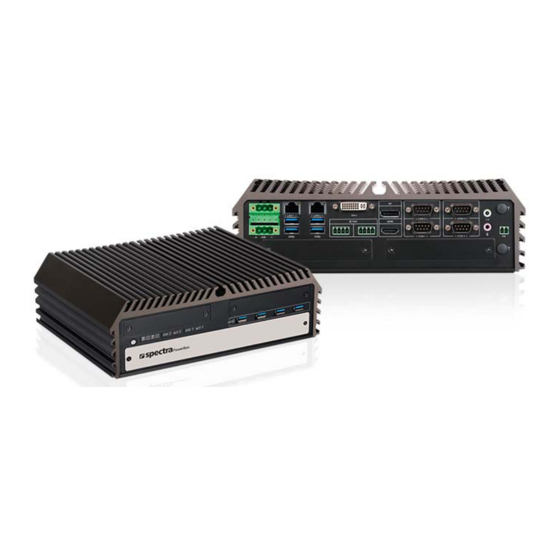
Page 15: Product Pictures
‐ M.2 E key (CNVi), full-size Mini-PCIe and M.2 M Key (NVMe SSD) ‐ Proprietary CMI interface for various I/O expandability ‐ Proprietary CFM interface for PoE+ or Power Ignition Sensing Spectra GmbH & Co. KG User Manual sales@spectra.de Spectra PowerBox 500... -
Page 16: Hardware Specification
• 4x RS-232/422/485 with Auto Flow Control (Support - Optional AC/DC 24V Power Adapter, 220W 5V/12V), DB9 • 4x 10Gbps USB3.2 Gen2 Ports, Type-A • 4x 5Gbps USB3.2 Gen1 Ports, Type-A Spectra GmbH & Co. KG User Manual sales@spectra.de Spectra PowerBox 500 16 ... - Page 17 Database: Telcordia SR-332 Issue 3, Method 1, Case 3 • Linux: Supports by project Certification • EMC: CE/FCC Class A, EN 50121-3-2, E-mark (Pending) • Safety: LVD (EN62368-1) Spectra GmbH & Co. KG User Manual sales@spectra.de Spectra PowerBox 500 17 ...
-
Page 18: System I/O
Used to reset the system USB3.2 Gen2 Universal I/O Bracket Used to connect to USB 3.2 Gen2/3.2 Used to customized I/O output with optional Gen1/2.0/1.1 compatible devices modules Spectra GmbH & Co. KG User Manual sales@spectra.de Spectra PowerBox 500 18 ... -
Page 19: Rear
Used to connect an antenna for optional wireless interface module HDMI Port Universal I/O Bracket Used to connect the system with HDMI monitor Used to customized I/O output with optional modules Spectra GmbH & Co. KG User Manual sales@spectra.de Spectra PowerBox 500 19 ... -
Page 20: Mechanical Dimension
1.7 Mechanical Dimension Spectra GmbH & Co. KG User Manual sales@spectra.de Spectra PowerBox 500 20 ... - Page 21 Chapter 2 Switches & Connectors Spectra GmbH & Co. KG User Manual sales@spectra.de Spectra PowerBox 500 21 ...
-
Page 22: Location Of Switches And Connectors
2.1 Location of Switches and Connectors 2.1.1 Top View Spectra GmbH & Co. KG User Manual sales@spectra.de Spectra PowerBox 500 22 ... -
Page 23: Bottom View
2.1.2 Bottom View Spectra GmbH & Co. KG User Manual sales@spectra.de Spectra PowerBox 500 23 ... -
Page 24: Switches And Connectors Definition
Remote Power On/Off Switch Connector SATA1, SATA2 22 PINs SATA Connector SIM1, SIM2 SIM Card Socket A and B SODIMM1, SODIMM2 DDR4 SO-DIMM USB3_1, USB3_2, USB3_3, USB3.2 Gen2/USB 2.0 port connector USB3_4 Spectra GmbH & Co. KG User Manual sales@spectra.de Spectra PowerBox 500 24 ... -
Page 25: Definition Of Switches
LED Status Status Blue Power off (S4/S5) Power LED Green Power on (S0) Blinking Blue & Green Stand by (S3) RESET1: Reset Switch Switch Definition Push Reset System Spectra GmbH & Co. KG User Manual sales@spectra.de Spectra PowerBox 500 25 ... - Page 26 0V(RI) ON (Default) ON (Default) COM4 SW3: Super CAP Switch Location Function DIP1 DIP2 Super CAP ON (Default) Enabled OFF (Default) Super CAP Disabled Spectra GmbH & Co. KG User Manual sales@spectra.de Spectra PowerBox 500 26 ...
-
Page 27: Definition Of Connectors
UIM_DATA_A USB_D- REFCLK- UIM_CLK_A USB_D+ REFCLK+ / UIM_PWR_B +3.3Vaux UIM_RESET_A +3.3Vaux UIM_VPP_A UIM_IC_DM / (UIM_CLK_B) UIM_IC_DP / (UIM_DATA_B) CL_CLK W_DISABLE1# CL_DATA PERST# +1.5V PERn0 CL_RST +3.3Vaux PERp0 +3.3Vaux Spectra GmbH & Co. KG User Manual sales@spectra.de Spectra PowerBox 500 27 ... - Page 28 CN4, CN6: Mini PCI-Express Socket (Support mPCIE & mSATA) Definition Definition WAKE# 3.3Vaux +1.5V SMB_CLK PETn0/SATA_TXN 1.5V SMB_DATA PETp0/SATA_TXP USB_D- REFCLK- USB_D+ REFCLK+ +3.3Vaux +3.3Vaux W_DISABLE1# PERST# +1.5V PERn0/SATA_RXP +3.3Vaux PERp0/SATA_RXN +3.3Vaux Spectra GmbH & Co. KG User Manual sales@spectra.de Spectra PowerBox 500 28 ...
- Page 29 WT_D0P/PERN1 LED2# CLINK_CLK CLKREQ1# WGR_D0P PERN0 COEX3 PEWAKE1# WT_CLKN/REFCLKP1 UART_WAKE# COEX_RXD 3.3V WGR_CLKN REFCLKP0 WT_CLKP/REFCLKN1 UART_RX/BRI_RSP COEX_TXD 3.3V WGR_CLKP REFCLKN0 KEY E SUSCLK KEY E KEY E PERST0# Spectra GmbH & Co. KG User Manual sales@spectra.de Spectra PowerBox 500 29 ...
- Page 30 PETP3 KEY M 3.3V SMB_CLK KEY M PERN0/SATA_B+ 3.3V SMB_DATA SUSCLK PERN2 PERP0/SATA_B- PEDET/CFG1 3.3V ALERT# 3.3V PERP2 3.3V CFG0 PETN0/SATA_A- 3.3V PETN2 PETP0/SATA_A+ CFG2 PERST*/NC PETP2 CLKREQ*/NC Spectra GmbH & Co. KG User Manual sales@spectra.de Spectra PowerBox 500 30 ...
- Page 31 FAN2:GPU (MXM) smart FAN connector Connector Type: 1x 4-pins Terminal Block , 3.5mm pitch FAN1 FAN2 Definition +12V FAN_IN 1 2 3 4 1 2 3 4 FAN_PWM Spectra GmbH & Co. KG User Manual sales@spectra.de Spectra PowerBox 500 31 ...
- Page 32 Connector Type: Terminal Block 1X2 2-pin, 3.5mm pitch Definition PWR_SW Warning!!! DO NOT APPLY POWER to the pins. 2 This port is only used to connect a SWITCH. Spectra GmbH & Co. KG User Manual sales@spectra.de Spectra PowerBox 500 32 ...
-
Page 33: Chapter 3 System Setup
Chapter 3 System Setup Spectra GmbH & Co. KG User Manual sales@spectra.de Spectra PowerBox 500 33 ... -
Page 34: Removing The Top Cover
1. Turn over the unit to have the bottom side face up, loosen the 6 screws on the bottom cover and place them aside for later use. 2. Remove the bottom cover from the chassis. Spectra GmbH & Co. KG User Manual sales@spectra.de Spectra PowerBox 500 34 ... - Page 35 3. Loosen the 4 screws. Pull out 4 latches as marked on photo. 4. Hold front and rear panel and lift up the body of unit vertically. 5. Turn over the body of the unit and place it gently. Spectra GmbH & Co. KG User Manual sales@spectra.de Spectra PowerBox 500 35 ...
-
Page 36: Install Cpu
Pull aside and then lift up the socket lever to unlock the socket. Align the notches on CPU with the alignment post on socket. Hold the CPU by the edges toward the notches and insert the CPU gently. Spectra GmbH & Co. KG User Manual sales@spectra.de Spectra PowerBox 500 36 ... - Page 37 Align the four mounting holes and put on the CPU heat sink. Please note: the sign “▽ Front” means to face the side of the thermal block to the front panel. Place the thermal pad on the CPU heat sink. Spectra GmbH & Co. KG User Manual sales@spectra.de Spectra PowerBox 500...
-
Page 38: Install So-Dimm
2. Insert a SO-DIMM at a 45-degree angle until its edge connector is connected to SO-DIMM socket firmly. 3. Press down the module until the retaining clips snap back in place. Spectra GmbH & Co. KG User Manual sales@spectra.de Spectra PowerBox 500... -
Page 39: Install A Mini-Pcie/Msata Card
Tilt a Mini PCIe card/mSATA Card at a 45-degree angle and insert it to the socket until the golden finger connector of the card seated firmly. Press the card down and secure it with 2 screws. Spectra GmbH & Co. KG User Manual sales@spectra.de Spectra PowerBox 500... -
Page 40: Install A M.2 E Key Card
2. Tilt the M.2 E Key card at a 45-degree angle and insert it to the socket until the golden finger connector of the card seated firmly. 3. Press the card down and secure it with 1 screw. Spectra GmbH & Co. KG User Manual sales@spectra.de Spectra PowerBox 500 40 ... -
Page 41: Install A M.2 M Key Card
HDD bay cover bracket. 2. Pull the rotating arm and HDD bracket out of system. 3. Locate the M.2 M Key slot (CN7) on the system board. Spectra GmbH & Co. KG User Manual sales@spectra.de Spectra PowerBox 500 41 ... - Page 42 4. Tilt the M.2 M Key card at a 45-degree angle and insert it to the socket until the golden finger connector of the card seated firmly. 5. Press the card down and secure it with the screw. Spectra GmbH & Co. KG User Manual sales@spectra.de Spectra PowerBox 500 42 ...
-
Page 43: Install Antennas
2. For Antenna #1, penetrate the antenna jack through the hole. For Antenna #2, loosen the screws on rear panel to remove the rear panel first, and place them aside for later use. Penetrate the antenna jack through the hole. Spectra GmbH & Co. KG User Manual sales@spectra.de Spectra PowerBox 500 43 ... - Page 44 Put on the washer and fasten the nut of antenna jack. 4. Assemble the antenna and antenna jack together Attach the RF connector at another end of the cable onto the card. Spectra GmbH & Co. KG User Manual sales@spectra.de Spectra PowerBox 500 44 ...
-
Page 45: Install The Thermal Pad Of Thermal Block
3.9 Install the Top Cover 1. Hold front and rear panel and put the body of unit back to the chassis. Spectra GmbH & Co. KG User Manual sales@spectra.de Spectra PowerBox 500 45 ... - Page 46 2. Push the four latches back into the chassis, and fasten the 4 screws as marked. 3. Put the bottom cover onto the system. 4. Fasten the 6 screws on the bottom cover. Spectra GmbH & Co. KG User Manual sales@spectra.de Spectra PowerBox 500 46 ...
-
Page 47: Remove The Front Cover Plate
3.11 Install a SATA Hard Drive at Front Panel 1. Loosen the screw to remove the HDD bay cover bracket. 2. Pull the rotating arm and pull the HDD bracket out of system. Spectra GmbH & Co. KG User Manual sales@spectra.de Spectra PowerBox 500 47 ... - Page 48 4. Align the HDD bracket with the entrance of HDD bay. Insert the HDD bracket and push it until the HDD connector is fully inserted into the SATA slot. 5. Place the rotating arm back and fasten the screw. Spectra GmbH & Co. KG User Manual sales@spectra.de Spectra PowerBox 500 48 ...
-
Page 49: Install A Sim Card
1. Fasten the cover by using the two screws. Note: It’s advised to fasten the 2 screws manually. If fastened with an electrical screw driver, please set the torque of the driver to 2.5 KgF. Spectra GmbH & Co. KG User Manual sales@spectra.de Spectra PowerBox 500 49 ... -
Page 50: Wall Mount
3.14 Wall Mount Spectra PowerBox 500 series offers wall mount kit that customers can install system on the wall in convenient and economical ways. 1. Locate mounting holes at the bottom side of system. Use provided 8 screws to fasten the bracket on each side. -
Page 51: Vesa Mount
VESA 75 mm. Red circles represent the use for VESA 100mm. 1. The following picture illustrates the installation of Spectra PowerBox 500 series on a VESA stand. Align the 4 screw holes of VESA stand with the screw holes on bottom side of system. -
Page 52: Chapter 4 Bios Setup
Chapter 4 BIOS Setup Spectra GmbH & Co. KG User Manual sales@spectra.de Spectra PowerBox 500 52 ... -
Page 53: Bios Introduction
Then you can use the control keys to enter values and move from field to field within a sub-menu. If you want to return to the main menu, just press the <Esc >. Spectra GmbH & Co. KG User Manual sales@spectra.de... -
Page 54: Main Setup
4.2.1 System Date Set the date. Please use <Tab> to switch between date elements. 4.2.2 System Time Set the time. Please use <Tab> to switch between time elements. Spectra GmbH & Co. KG User Manual sales@spectra.de Spectra PowerBox 500 54 ... -
Page 55: Advanced Setup
■ Active Process Cores [All] Allows users to choose the number of active processor cores. Configuration options: [All] [1] [2] [3] [4] [5]; if 6 cores CPU is used. Spectra GmbH & Co. KG User Manual sales@spectra.de Spectra PowerBox 500... -
Page 56: Power & Performance
4.3.3 SATA Configuration ■ SATA Controller(s) [Enabled] Enables or disables Serial ATA controller. ■ SATA Mode Selection [AHCI] This item allows users to choose [AHCI] or [RAID] mode. Spectra GmbH & Co. KG User Manual sales@spectra.de Spectra PowerBox 500 56 ... -
Page 57: Pch-Fw Configuration
Port 1 [Enabled] Enables or disables SATA Port 5. 4.3.4 PCH-FW Configuration ■ Intel AMT [Enabled] Allows users to enable or disable Intel® Active Management Technology BIOS execution. Spectra GmbH & Co. KG User Manual sales@spectra.de Spectra PowerBox 500 57 ... -
Page 58: Trusted Computing
4.3.5 Trusted Computing ■ Security Device Support [Disable] Allow users to enable or disable Security Device Support function. ■ SHA-1 PCR Bank [Enabled] Enables or disables SHA-1 PCR Bank function. Spectra GmbH & Co. KG User Manual sales@spectra.de Spectra PowerBox 500 58 ... -
Page 59: Acpi Settings
Allows users to select the highest Advanced Configuration Power Interface® (ACPI) sleep state that system will enter when suspend button is pressed. [Suspend Disabled]: Disables entering suspend state. [S3 (suspend to RAM)]: Enables suspend to RAM state. Spectra GmbH & Co. KG User Manual sales@spectra.de Spectra PowerBox 500... -
Page 60: F81866 Super Io Configuration
This item allows users to enable or disable serial port. Change Settings [Auto] This item allows users to change the address & IRQ settings of the specified serial port. Spectra GmbH & Co. KG User Manual sales@spectra.de Spectra PowerBox 500... -
Page 61: Hardware Monitor
Allows users to setting CPU smart fan parameters. ■ GPU Smart Fan Function [Enabled] Enables or disables GPU Smart Fan function. ■ GPU Smart Fan Configuration Allows users to setting GPU smart fan parameters. Spectra GmbH & Co. KG User Manual sales@spectra.de Spectra PowerBox 500 61 ... -
Page 62: S5 Rtc Wake Settings
[Dynamic Time]: Set the increase time from current time to wake system. 4.3.10 Serial Port Console Redirection ■ Console Redirection [Disabled] These items allow users to enable or disable COM0, COM1, COM2, COM3, Com4, COM5 console redirection function. Spectra GmbH & Co. KG User Manual sales@spectra.de Spectra PowerBox 500 62 ... -
Page 63: Usb Configuration
This item allows users to enable or disable XHCI (USB3.2) hand-off function. ■ USB Mass Storage Driver Support [Enabled] Enables or disables support for USB mass storage devices. 4.3.12 Network Stack Configuration Spectra GmbH & Co. KG User Manual sales@spectra.de Spectra PowerBox 500... - Page 64 Controls the execution of UEFI and Legacy Video option ROM. [Do not launch]: Disables option ROM execution. [UEFI]: Enables UEFI option ROM only. [Legacy]: Enables legacy option ROM only. Spectra GmbH & Co. KG User Manual sales@spectra.de Spectra PowerBox 500...
- Page 65 4.3.14 NVMe Configuration The screen allows users to select options for the NVMe configuration, and change the value of the selected option. The options will show as the NVME Device is found. Spectra GmbH & Co. KG User Manual sales@spectra.de Spectra PowerBox 500 65 ...
-
Page 66: Chipset Setup
This section allows you to configure chipset related settings according to user’s preference. 4.4.1 System Agent (SA) Configuration ■ Memory Configuration This item displays detailed memory information in the system. Spectra GmbH & Co. KG User Manual sales@spectra.de Spectra PowerBox 500... - Page 67 BIOS. Configuration options: [Auto] [Disabled] [Enabled] ■ VT-d [Enabled] This item allows users to enable or disable Intel® Virtualization Technology for Directed I/O (VT-d) function. Spectra GmbH & Co. KG User Manual sales@spectra.de Spectra PowerBox 500...
-
Page 68: Pch-Io Configuration
Configuration options: [Auto] [Gen1] [Gen2] [Gen3]. PCI Express Root Port (CN2 mPCIe) PCI Express Root Port [Enabled] Allows you to enable or disable the PCI Express Port. Spectra GmbH & Co. KG User Manual sales@spectra.de Spectra PowerBox 500... - Page 69 [Disabled]: HD Audio device is unconditionally disabled. ■ LAN i219LM Controller [Enabled] Enables or disables i219LM LAN Controller. ■ Wake On LAN (i219) [Enabled] Enables or disables integrated LAN i219LM Wake on LAN function. Spectra GmbH & Co. KG User Manual sales@spectra.de Spectra PowerBox 500 69 ...
- Page 70 (G3 state). [Always on]: Enters to power on state. [Always off]: Enters to power off state. [Keep last state]: Enters to the last power state before a power failure. Spectra GmbH & Co. KG User Manual sales@spectra.de Spectra PowerBox 500...
-
Page 71: Security Setup
User Password controls access to the system at boot and to the BIOS Setup utility. 4.5.3 Security Boot Secure Boot [Disabled] Enable or disable Secure Boot function. Secure Boot Mode [Standard] Spectra GmbH & Co. KG User Manual sales@spectra.de Spectra PowerBox 500 71 ... -
Page 72: Boot Setup
Allows users to select the power-on state for keyboard NumLock. 4.6.3 Quiet Boot [Disabled] Allows users to enable or disable Quiet Boot function. 4.6.4 Fast Boot [Disabled] Allows users to enable or disable Fast Boot function. Spectra GmbH & Co. KG User Manual sales@spectra.de Spectra PowerBox 500 72 ... -
Page 73: Save & Exit
This item allows users to save the changes done so far as user defaults. 4.7.9 Restore User Defaults This item allows users to restore the user defaults to all the options. Spectra GmbH & Co. KG User Manual sales@spectra.de Spectra PowerBox 500... -
Page 74: Chapter 5 Product Application
Chapter 5 Product Application (For PB-500-DIO Only) Spectra GmbH & Co. KG User Manual sales@spectra.de Spectra PowerBox 500 74 ... -
Page 75: Digital I/O (Dio) Application
GPIO72 (Pin105) GPIO73 (Pin106) GPIO74 (Pin107) GPIO75 (Pin108) GPIO76 (Pin109) GPIO77 (Pin110) GPIO80 (Pin111) GPIO81 (Pin112) GPIO82 (Pin113) GPIO83 (Pin114) GPIO84 (Pin115) GPIO85 (Pin116) GPIO86 (Pin117) GPIO87 (Pin118) Spectra GmbH & Co. KG User Manual sales@spectra.de Spectra PowerBox 500 75 ... - Page 76 Following is an example to enable configuration and to disable configuration by using debug. -o 4e 87 -o 4e 87 (enable configuration) -o 4e aa (disable configuration) 5.1.1.3 Relative Registers To program the F81866A configuration registers, see the following configuration procedures. Spectra GmbH & Co. KG User Manual sales@spectra.de Spectra PowerBox 500 76 ...
- Page 77 Spectra GmbH & Co. KG User Manual sales@spectra.de Spectra PowerBox 500 77 ...
- Page 78 // Set (bit 0~7) = 0 to select GP 70~77 as Input mode. <Input Value> WriteByte(AddrPort, 0x82) // Select configuration register 82h ReadByte(DataPort, Value) // Read bit 0~7 (0xFF)= GP70 ~77 as High. <Leave the Extended Function Mode> WriteByte(AddrPort, 0xAA) Spectra GmbH & Co. KG User Manual sales@spectra.de Spectra PowerBox 500 78 ...
- Page 79 WriteByte(AddrPort, 0x89) // Select configuration register 89h WriteByte(DataPort, Value) // Set bit 0~7=(0/1) to output GP 80~87 as Low or High <Leave the Extended Function Mode> WriteByte(AddrPort, 0xAA) Spectra GmbH & Co. KG User Manual sales@spectra.de Spectra PowerBox 500 79 ...
- Page 80 WriteByte(DataPort, (0x0A)) WriteByte(AddrPort, 0x61) // Select configuration register 61h (Low Byte address) WriteByte(DataPort, (0x00)) <Leave the Extended Function Mode> WriteByte(AddrPort, 0xAA) default GPIO Port base address is 0xA00h Spectra GmbH & Co. KG User Manual sales@spectra.de Spectra PowerBox 500 80 ...
- Page 81 = DI2 = DO2 = DI3 = DO3 = DI4 = DO4 = DI5 = DO5 = DI6 = DO6 = DI7 = DO7 = DI8 = DO8 Spectra GmbH & Co. KG User Manual sales@spectra.de Spectra PowerBox 500 81 ...
-
Page 82: Digital I/O (Dio) Hardware Specification
Signal High Level: Pull up resistor to XCOM+ ‐ Signal Low Level: = XCOM- ‐ Sink Current: 1A (Max) ‐ Spectra GmbH & Co. KG User Manual sales@spectra.de Spectra PowerBox 500 82 ... -
Page 83: Dio Connector Definition
DIO1/DIO2: Digital Input / Output Connector Connector Type: Terminal Block 2X10 10-pin, 3.5mm pitch Pin1 Pin1 DIO1 (Digital Input) DIO2 (Digital Output) Location Definition Location Definition DC INPUT DC INPUT (XCOM+) (XCOM+) DIO1 DIO2 (XCOM-) (XCOM-) Spectra GmbH & Co. KG User Manual sales@spectra.de Spectra PowerBox 500 83 ... - Page 84 Reference Input Circuit Reference Output Circuit Spectra GmbH & Co. KG User Manual sales@spectra.de Spectra PowerBox 500 84 ...
- Page 85 Chapter 6 Optional Modules & Accessories Pin Definitions and Settings Spectra GmbH & Co. KG User Manual sales@spectra.de Spectra PowerBox 500 85 ...
-
Page 86: Pb-500-M12 Module Pin Definition & Settings
Connector Type: M12 A coded 8pin connector POE type: Midspan (B-Type) Definition Definition 2_LAN1_0+ 2_LAN1_0- 2_LAN1_2+ 2_LAN1_1+ (Power PIN) 2_LAN1_2- 2_LAN1_1- (Power PIN) 2_LAN1_3+ 2_LAN1_3- (Power PIN) (Power PIN) Spectra GmbH & Co. KG User Manual sales@spectra.de Spectra PowerBox 500 86 ... -
Page 87: Pb-500-Com Module Pin Definition & Settings
SW2 on CMI PB-500-COM Module: COM5/COM6 Power Select Location Function DIP1 DIP2 0V(RI) ON (Default) ON (Default) COM5 Location Function DIP3 DIP4 0V(RI) ON (Default) ON (Default) COM6 Spectra GmbH & Co. KG User Manual sales@spectra.de Spectra PowerBox 500 87 ... -
Page 88: Pb-500-Ign Module Pin Definition & Settings
Default setting of Pin1 to Pin4 is OFF/OFF/OFF/OFF. 24V_12V_1: IGN Module Voltage Mode Setting Switch 12V / 24V Car Battery Switch 1 2 3 Definition 12V Car Battery Input (Default) 24V Car Battery Input Spectra GmbH & Co. KG User Manual sales@spectra.de Spectra PowerBox 500 88 ... -
Page 89: Install An Mxm Module
6.4 Install an MXM Module Locate the connector of MXM carrier board (J1) on the top side of system. Insert the MXM carrier board vertically to the connector on the system mainboard. Spectra GmbH & Co. KG User Manual sales@spectra.de Spectra PowerBox 500 89 ... - Page 90 Place the thermal pad on the chip of MXM Module. Insert the MXM Module into the slot on the MXM carrier board at 45 degrees. Spectra GmbH & Co. KG User Manual sales@spectra.de Spectra PowerBox 500...
- Page 91 Put on the thermal block with aligning the four screw-holes, and fasten the four screws. Place the thermal pad on the thermal block. Replace the cover plate at front panel by the accompanying bracket with 4x DP cutout. Spectra GmbH & Co. KG User Manual sales@spectra.de Spectra PowerBox 500 91 ...
-
Page 92: Install A High Speed Cmi Module
6.5 Install a High Speed CMI Module The applicable high speed CMI modules for Spectra PowerBox 500 series are listed in the following table. Model No. Product Description CMI Module with 4x Intel I210-IT GbE LAN, RJ45 Port / 1x... - Page 93 Loosen the 2 screws on the front panel to remove the cover plate. Locate the connector of CMI-module (BTB_FH4) on the top side of system. Replace the screw by copper pillar before insert the CMI module. Spectra GmbH & Co. KG User Manual sales@spectra.de Spectra PowerBox 500 93 ...
- Page 94 Insert the CMI module vertically to the female connector on the system mainboard. Fasten the 4 screws to fix it. Attach the M12 I/O bracket, and fasten the two screws and four hex rings to fix it. Spectra GmbH & Co. KG User Manual sales@spectra.de Spectra PowerBox 500 94 ...
-
Page 95: Install A Pb-500-Poe Module
6.6 Install a PB-500-PoE Module The PB-500-PoE module for Spectra PowerBox 500 series is installed on the PB-500-LAN or the PB-500-LAN-M12 module. Model No. Product Description CMI Module with 4x Intel I210-IT GbE LAN, RJ45 Port / 1x PB-500-PoE Universal Bracket with 4x RJ45 Cutout / CFM Module with PoE Control Function, Individual Port 25.5W... - Page 96 Turn over the heatsink of PB-500-PoE and locate the two places marked by red squares. Paste the two thermal pads for PB-500-PoE onto the heatsink carefully. Spectra GmbH & Co. KG User Manual sales@spectra.de Spectra PowerBox 500...
- Page 97 PB-500-LAN-M12 module. Fasten 4 screws to fix it. Paste the last thermal pad onto the heatsink carefully, and then execute the step 6 in chapter 6-6 to complete the installation. Spectra GmbH & Co. KG User Manual sales@spectra.de Spectra PowerBox 500...
-
Page 98: Install A Pb-500-Dio Module
Locate the connector of CMI-module (BTB_FH1) on the bottom side of system. Loosen the 2 screws on rear panel to remove the cover plate Penetrate the PB-500-DIO module through the area with an inclined angle. Spectra GmbH & Co. KG User Manual sales@spectra.de Spectra PowerBox 500 98 ... - Page 99 Insert the PB-500-DIO module carefully to the CMI connector on main board. Fix it with the two screws as indicated. Attach the PB-500-DIO bracket, and fasten the two screws to fix it. Spectra GmbH & Co. KG User Manual sales@spectra.de Spectra PowerBox 500...
-
Page 100: Install A Pb-500-Com Module
1. Locate the connector of CMI-module (BTB_FH1) on the bottom side of system. 2. Loosen the 2 screws on rear panel to remove the cover plate Penetrate the PB-500-COM module through the area with an inclined angle. Spectra GmbH & Co. KG User Manual sales@spectra.de Spectra PowerBox 500 100 ... - Page 101 Loosen the 4 D-Sub jack screws as marked on photo. Attach the COM bracket. Fasten 2 screws and 4 D-Sub jack screws to fix it. Spectra GmbH & Co. KG User Manual sales@spectra.de Spectra PowerBox 500...
-
Page 102: Install An Pb-500-Ign Module
Locate the power Ignition connector (IGN_PH1) on system motherboard as indicated. Insert the connector of power ignition board to the female connector on system motherboard. Fasten two screws to secure the power ignition board. Spectra GmbH & Co. KG User Manual sales@spectra.de Spectra PowerBox 500... -
Page 103: Install An External Fan
1. Prepare an external fan. Loosen the 2 screws halfway on mounting frame before attempting to install it. 2. Slide the FAN into the groove of chassis as illustrated. Spectra GmbH & Co. KG User Manual sales@spectra.de Spectra PowerBox 500... - Page 104 3. Tighten the 2 screws to fix it onto chassis. 4. Insert the plug of the external fan to the external fan power connector. Spectra GmbH & Co. KG User Manual sales@spectra.de Spectra PowerBox 500 104 ...
-
Page 105: Din-Rail Mount Brackets
6.11 DIN-Rail Mount Brackets Spectra PowerBox 500 series offers DIN-Rail Mount that customer can install system on the DIN Rail. 1. Please refer to section 3.14 Wall Mount Brackets to install mounting bracket at both sides of system. Fasten 2 DIN rail mounting clips to mounting brackets on both sides with provided 4 screws as illustrated. -
Page 106: Side Mount Bracket
6.12 Side Mount Bracket Spectra PowerBox 500 series offers Side Mount Bracket that customer can install system to the right or left side of wall to create effective of space. 1. The mounting holes are at the bottom side of system. Fasten the 8 screws to fix the side mount bracket with system together. - Page 107 ...
Need help?
Do you have a question about the PowerBox 500 Series and is the answer not in the manual?
Questions and answers